Note: Descriptions are shown in the official language in which they were submitted.
CA 03132376 2021-09-01
WO 2020/197908
PCT/US2020/023489
COMPOSITE BEARING AND METHOD OF MAKING AND USING THE SAME
TECHNICAL FIELD
This disclosure relates to bearing assemblies and methods of making and using
the same. By non-limiting example, the assembly can be used in a bearing for a
suspension assembly for a vehicle.
BACKGROUND
Bearings made of composite materials including a substrate and a low friction
layer overlay are generally known. Such bearings can be used, for example, in
a
suspension assembly. A suspension assembly may be used to connect a vehicle
component relative to another vehicle component and provide cushioning or
damping
to control movement of the components. The suspension assembly can be used in
vehicles such as bicycles, motorcycles, ATVs, cars, trucks, SUVs, aircraft,
watercraft,
or in other vehicles. Typically, a suspension system may allow one component
to
move past another component, such as between inner component (such as a
shaft), to
an outer component (such as housing) with a bearing between the two
components.
However, current bearing designs may contribute to undesirable
characteristics, such
as vibration, stick-slip, and friction within components of the vehicle
suspension,
which may lead to undesirable suspension characteristics such as suspension
sag,
improper bump absorption, or misalignment within components of the suspension
assembly. Therefore, there exists a need for improved bearings particularly
suited for
suspension assemblies.
BRIEF DESCRIPTION OF THE DRAWINGS
The present disclosure may be better understood, and its numerous features
and advantages made apparent to those skilled in the art by referencing the
accompanying drawings.
FIG. 1 includes a method of producing a bearing in accordance with an
embodiment;
FIG. 2A includes an illustration of a cross-sectional view of a bearing in
accordance with an embodiment;
FIG. 2B includes an illustration of a cross-sectional view of a bearing in
accordance with an embodiment;
- 1 -
CA 03132376 2021-09-01
WO 2020/197908
PCT/US2020/023489
FIG. 3 includes an illustration of a bearing according to a number of
embodiments;
FIG. 4 includes an illustration of a bearing according to a number of
embodiments;
FIG. 5A includes an illustration of a cross-sectional view of a bearing
according to a number of embodiments;
FIG. 5B is an illustration of a cross-sectional view of a bearing according to
a
number of embodiments;
FIG. 6 includes an illustration of a bearing within an assembly according to a
number of embodiments;
FIG. 7 includes an illustration of a bearing within an assembly according to a
number of embodiments;
FIG. 8 includes an illustration of a bearing within an assembly according to a
number of embodiments; and
FIG. 9 includes an illustration of a graph of time versus the dynamic friction
force in the axial direction of a bearing in comparison to existing prior art
bearings
according to a number of embodiments.
Skilled artisans appreciate that elements in the figures are illustrated for
simplicity and clarity and have not necessarily been drawn to scale. For
example, the
dimensions of some of the elements in the figures may be exaggerated relative
to
other elements to help to improve understanding of embodiments of the
invention.
The use of the same reference symbols in different drawings indicates similar
or
identical items.
DETAILED DESCRIPTION OF THE PREFERRED EMBODIMENT(S)
The following description in combination with the figures is provided to
assist
in understanding the teachings disclosed herein. The following discussion will
focus
on specific implementations and embodiments of the teachings. This focus is
provided to assist in describing the teachings and should not be interpreted
as a
limitation on the scope or applicability of the teachings. However, other
embodiments can be used based on the teachings as disclosed in this
application.
The terms "comprises," "comprising," "includes," "including," "has,"
"having" or any other variation thereof, are intended to cover a non-exclusive
inclusion. For example, a method, article, or apparatus that comprises a list
of
- 2 -
CA 03132376 2021-09-01
WO 2020/197908
PCT/US2020/023489
features is not necessarily limited only to those features but may include
other
features not expressly listed or inherent to such method, article, or
apparatus. Further,
unless expressly stated to the contrary, "or" refers to an inclusive-or and
not to an
exclusive-or. For example, a condition A or B is satisfied by any one of the
following: A is true (or present) and B is false (or not present), A is false
(or not
present) and B is true (or present), and both A and B are true (or present).
Also, the use of "a" or "an" is employed to describe elements and components
described herein. This is done merely for convenience and to give a general
sense of
the scope of the invention. This description should be read to include one, at
least
one, or the singular as also including the plural, or vice versa, unless it is
clear that it
is meant otherwise. For example, when a single embodiment is described herein,
more than one embodiment may be used in place of a single embodiment.
Similarly,
where more than one embodiment is described herein, a single embodiment may be
substituted for that more than one embodiment.
Unless otherwise defined, all technical and scientific terms used herein have
the same meaning as commonly understood by one of ordinary skill in the art to
which this invention belongs. The materials, methods, and examples are
illustrative
only and not intended to be limiting. To the extent not described herein, many
details
regarding specific materials and processing acts are conventional and may be
found in
textbooks and other sources within the bearing and bearing assembly arts.
Embodiments described herein are generally directed to a bearing and methods
of creating and using a bearing within an assembly. In particular embodiments,
the
bearing may have a bearing sidewall defining an axial length, L, of the
bearing, where
the sidewall includes a flat portion, a first convex axial end, and a second
convex
axial end.
For purposes of illustration, FIG. 1 includes a diagram showing a forming
process 10 for forming a bearing. The forming process 10 may include a first
step 12
of providing a base material, a second step 14 of coating the base material
with a low
friction coating to form a composite material and a third step 16 of forming
the
composite material into a bearing.
Referring to the first step 12, the base material may be a substrate. In an
embodiment, the substrate can at least partially include a metal. According to
certain
embodiments, the metal may include iron, copper, titanium, tin, aluminum,
alloys
- 3 -
CA 03132376 2021-09-01
WO 2020/197908
PCT/US2020/023489
thereof, or may be another type of metal. More particularly, the substrate can
at least
partially include a steel, such as, a stainless steel, carbon steel, or spring
steel. For
example, the substrate can at least partially include a 301 stainless steel.
The 301
stainless steel may be annealed, 1/4 hard, 1/2 hard, 3/4 hard, or full hard.
In an
embodiment, the substrate may include a woven mesh or an expanded metal grid.
FIG. 2A includes an illustration of the composite material 1000 that may be
formed according to first step 12 and second step 14 of the forming process
10. For
purposes of illustration, FIG. 2A shows the layer by layer configuration of a
composite material 1000 after second step 14. In a number of embodiments, the
composite material 1000 may include a substrate 1119 (i.e., the base material
noted
above and provided in the first step 12) and a low friction layer 1104 (i.e.,
the low
friction coating applied in second step 14). The low friction layer 1104 can
be
coupled to at least a portion of the substrate 1119. In a particular
embodiment, the
low friction layer 1104 can be coupled to a surface of the substrate 1119 so
as to form
a low friction interface with another component. In the case of an annular
component,
such as a generally cylindrical component, the low friction layer 1104 can be
coupled
to the radially inner or outer surface of the substrate 1119 so as to form a
low friction
interface with another component. The substrate 1119 can have a thickness, Ts,
of
between about 1 micron to about 3000 microns, such as between about 50 microns
and about 1500 microns, such as between about 100 microns and about 1000
microns,
such as between about 200 microns and about 800 microns. In a number of
embodiments, the substrate 1119 may have a thickness, Ts, of between about 100
and
800 microns. In a number of embodiments, the substrate 1119 may have a
thickness,
Ts, of between about 200 and 550 microns. It will be further appreciated that
the
thickness, Ts, of the substrate 1119 may be any value between any of the
minimum
and maximum values noted above. The thickness of the substrate 1119 may be
uniform, i.e., a thickness at a first location of the substrate 1119 can be
equal to a
thickness at a second location therealong. The thickness of the substrate 1119
may be
non-uniform, i.e., a thickness at a first location of the substrate 1119 can
be different
than a thickness at a second location therealong. In a number of embodiments,
the
substrate 1119 may extend at least partially along a length of the composite
material
1000.
- 4 -
CA 03132376 2021-09-01
WO 2020/197908
PCT/US2020/023489
In a number of embodiments, the low friction layer 1104 can include a low
friction material. Low friction materials may include, for example, a polymer,
such as
a polyketone, a polyaramid, a polyimide, a polyetherimide, a polyphenylene
sulfide, a
polyetherslfone, a polysulfone, a polypheylene sulfone, a polyamideimide,
ultra high
molecular weight polyethylene, a fluoropolymer, a polyamide, a
polybenzimidazole, a
polyacetal, polybutylene terephthalate, polyethylene terephthalate,
polyethylene,
polyphenylene oxide, polyurethane, polyester, liquid crystal polymer (LCP), a
derivation thereof, or a combination thereof. In a particular example, the low
friction
layer 1104 may include polyketone, such as polyether ether ketone (PEEK),
polyether
ketone, polyether ketone ketone, polyether ketone ether ketone, a derivative
thereof,
or a combination thereof. In an additional example, the low friction layer
1104 may
be include a fluoropolymer, such as fluorinated ethylene propylene (FEP),
polytetrafluoroethylene (PTFE), polyvinylidene fluoride (PVDF),
perfluoroalkoxy
(PFA), a terpolymer of tetrafluoroethylene, hexafluoropropylene, and
vinylidene
fluoride (THV), polychlorotrifluoroethylene (PCTFE), ethylene
tetrafluoroethylene
copolymer (ETFE), or ethylene chlorotrifluoroethylene copolymer (ECTFE). The
low friction layer 1104 may further include a solid based material including
lithium
soap, graphite, boron nitride, molybdenum disulfide, tungsten disulfide,
polytetrafluoroethylene, carbon nitride, tungsten carbide, or diamond like
carbon, a
metal (such as aluminum, zinc, copper, magnesium, tin, platinum, titanium,
tungsten,
iron, bronze, steel, spring steel, stainless steel), a metal alloy (including
the metals
listed), an anodized metal (including the metals listed) or any combination
thereof.
In a number of embodiments, the low friction layer 1104 may further include
fillers, including glass fibers, carbon fibers, silicon, PEEK, aromatic
polyester, carbon
particles, bronze, fluoropolymers, thermoplastic fillers, aluminum oxide,
polyamidimide (PAI), PPS, polyphenylene sulfone (PPS02), LCP, aromatic
polyesters, molybdenum disulfide, tungsten disulfide, graphite, graphene,
expanded
graphite, boron nitrade, talc, calcium fluoride, BaSO4, iron oxide, or any
combination
thereof. Additionally, the filler can include alumina, silica, titanium
dioxide, calcium
fluoride, boron nitride, mica, Wollastonite, silicon carbide, silicon nitride,
zirconia,
carbon black, pigments, or any combination thereof. Fillers can be in the form
of
beads, fibers, powder, mesh, or any combination thereof.
- 5 -
CA 03132376 2021-09-01
WO 2020/197908
PCT/US2020/023489
In an embodiment, the low friction layer 1104 can have a thickness, TFL, of
between about 1 micron to about 500 microns, such as between about 10 microns
and
about 450 microns, such as between about 50 microns and about 350 microns,
such as
between about 100 microns and about 300 microns. In a number of embodiments,
the
low friction layer 1104 may have a thickness, TFL, of between about 50 and 330
microns. It will be further appreciated that the thickness, TFL, of the low
friction layer
1104 may be any value between any of the minimum and maximum values noted
above. The thickness of the low friction 1104 may be uniform, i.e., a
thickness at a
first location of the low friction layer 1104 can be equal to a thickness at a
second
location therealong. The thickness of the low friction 1104 may be non-
uniform, i.e.,
a thickness at a first location of the low friction layer 1104 can be
different than a
thickness at a second location therealong. The low friction layer 1104 may
overlie
one major surface of the substrate 1119, shown, or overlie both major
surfaces. The
substrate 1119 may be at least partially encapsulated by the low friction
layer 1104.
That is, the low friction layer 1104 may cover at least a portion of the
substrate 1119.
Axial surfaces of the substrate 1119 may or may not be exposed from the low
friction
layer 1104.
In an embodiment, the composite material 1001 may also include at least one
adhesive layer 1121 that may couple the low friction layer 1104 to the
substrate 1119
(i.e., the base material provided in the first step 12) and a low friction
layer 1104 (i.e.,
the low friction coating applied in second step 14). In another alternate
embodiment,
the substrate 1119, as a solid component, woven mesh or expanded metal grid,
may
be embedded between at least one adhesive layer 1121 included between the low
friction layer 1104 and the substrate 1119.
The adhesive layer 1121 may include any known adhesive material common
to the bearing arts including, but not limited to, epoxy resins, polyimide
resins,
polyether/polyamide copolymers, ethylene vinyl acetates, ethylene
tetrafluoroethylene
(ETFE), ETFE copolymer, perfluoroalkoxy (PFA), or any combination thereof.
Additionally, the adhesive can include at least one functional group selected
from -
.. C=0, -C-O-R, -COH, -COOH, -COOR, -CF2=CF-OR, or any combination thereof,
where R is a cyclic or linear organic group containing between 1 and 20 carbon
atoms. Additionally, the adhesive can include a copolymer. In an embodiment,
the
hot melt adhesive can have a melting temperature of not greater than 450 C,
such as
- 6 -
CA 03132376 2021-09-01
WO 2020/197908
PCT/US2020/023489
not greater than 320 C. In another embodiment, the adhesive may break down
above
300 C, such as above 220 C. In further embodiments, the melting temperature of
the
hot melt adhesive can be higher than 250 C or even higher than 300 C. The
adhesive
layer 1121 can have a thickness, TAL, of between about 1 micron to about 100
microns, such as between about 10 microns and about 50 microns. In a number of
embodiments, the adhesive layer 1121 may have a thickness, TAL, of between
about
20 and 50 microns. It will be further appreciated that the thickness, TAL, of
the
adhesive layer 1121 may be any value between any of the minimum and maximum
values noted above. The thickness of the adhesive layer 1121 may be uniform,
i.e., a
thickness at a first location of the adhesive layer 1121 can be equal to a
thickness at a
second location therealong. The thickness of the adhesive layer 1121 may be
non-
uniform, i.e., a thickness at a first location of the adhesive layer 1121 can
be different
than a thickness at a second location therealong.
FIG. 2B includes an illustration of another embodiment. According to this
particular embodiment, the composite material 1003 may be similar to the
composite
material 1000 of FIG. 2A, except this composite material 1003 may also include
corrosion protection layers 1704, 1705, and 1708, and a corrosion resistant
layer 1125
that can include an adhesion promoter layer 1127 and an epoxy layer 1129 that
may
couple to the substrate 1119 (i.e., the base material provided in the first
step 12) and a
low friction layer 1104 (i.e., the low friction coating applied in second step
14).
The substrate 1119 may be coated with corrosion protection layers 1704 and
1705 to prevent corrosion of the substrate 1119 prior to processing.
Additionally, a
corrosion protection layer 1708 can be applied over layer 1704. Each of layers
1704,
1705, and 1708 can have a thickness of about 1 to 50 microns, such as about 7
to 15
microns. Layers 1704 and 1705 can include a phosphate of zinc, iron,
manganese, or
any combination thereof, or a nano-ceramic layer. Further, layers 1704 and
1705 can
include functional silanes, nano-scaled silane based primers, hydrolyzed
silanes,
organosilane adhesion promoters, solvent/water based silane primers,
chlorinated
polyolefins, passivated surfaces, commercially available zinc
(mechanical/galvanic)
or zinc-nickel coatings, or any combination thereof. Layer 1708 can include
functional silanes, nano-scaled silane based primers, hydrolyzed silanes,
organosilane
adhesion promoters, solvent/water based silane primers. Corrosion protection
layers
1704, 1706, and 1708 can be removed or retained during processing.
- 7 -
CA 03132376 2021-09-01
WO 2020/197908
PCT/US2020/023489
As stated above, the composite material 1003 may further include a corrosion
resistant layer 1125. The corrosion resistant layer 1125 can have a thickness
of about
1 to 50 microns, such as about 5 to 20 microns, and such as about 7 to 15
microns.
The corrosion resistant layer 1125 can include an adhesion promoter layer 1127
and
an epoxy layer 1129. The adhesion promoter layer 1127 can include a phosphate
of
zinc, iron, manganese, tin, or any combination thereof, or a nano-ceramic
layer. The
adhesion promoter layer 1127 can include functional silanes, nano-scaled
silane based
layers, hydrolyzed silanes, organosilane adhesion promoters, solvent/water
based
silane primers, chlorinated polyolefins, passivated surfaces, commercially
available
zinc (mechanical / galvanic) or Zinc-Nickel coatings, or any combination
thereof.
The epoxy layer 1129 can be a thermal cured epoxy, a UV cured epoxy, an IR
cured
epoxy, an electron beam cured epoxy, a radiation cured epoxy, or an air cured
epoxy.
Further, the epoxy layer 1129 can include polyglycidylether, diglycidylether,
bisphenol A, bisphenol F, oxirane, oxacyclopropane, ethylenoxide, 1,2-
epoxypropane,
2-methyloxirane, 9,10-epoxy-9,10-dihydroanthracene, or any combination
thereof.
The epoxy layer 1129 can further include a hardening agent. The hardening
agent can
include amines, acid anhydrides, phenol novolac hardeners such as phenol
novolac
poly[N-(4-hydroxyphenyl)maleimide] (PHPMI), resole phenol formaldehydes, fatty
amine compounds, polycarbonic anhydrides, polyacrylate, isocyanates,
encapsulated
polyisocyanates, boron trifluoride amine complexes, chromic-based hardeners,
polyamides, or any combination thereof. Generally, acid anhydrides can conform
to
the formula R-C=0-0-C=O-R' where R can be CxHyXzAu as described above.
Amines can include aliphatic amines such as monoethylamine,
diethylenetriamine,
triethylenetetraamine, and the like, alicyclic amines, aromatic amines such as
cyclic
aliphatic amines, cyclo aliphatic amines, amidoamines, polyamides,
dicyandiamides,
imidazole derivatives, and the like, or any combination thereof. Generally,
amines
can be primary amines, secondary amines, or tertiary amines conforming to the
formula R1R2R3N where R can be CxHyXzAu as described above. In an embodiment,
the epoxy layer 1129 can include fillers to improve the conductivity, such as
carbon
fillers, carbon fibers, carbon particles, graphite, metallic fillers such as
bronze,
aluminum, and other metals and their alloys, metal oxide fillers, metal coated
carbon
fillers, metal coated polymer fillers, or any combination thereof. The
conductive
fillers can allow current to pass through the epoxy coating and can increase
the
- 8 -
CA 03132376 2021-09-01
WO 2020/197908
PCT/US2020/023489
conductivity of the coated bearing as compared to a coated bearing without
conductive fillers.
In an embodiment, the composite material 1000, 1003 can have a thickness,
Tsw, in a range of 0.01 mm and 4 mm, such as in a range of 0.15 mm and 2.5 mm,
or
even in a range of 0.2 mm and 1 mm. It will be further appreciated that the
thickness,
Tsw of the composite material 1000, 1003 may be any value between any of the
minimum and maximum values noted above. The thickness, Tsw of the composite
material 1000, 1003 may be uniform, i.e., a thickness at a first location of
the
composite material 1000, 1003 can be equal to a thickness at a second location
therealong. The thickness, Tsw of the composite material 1000, 1003 may be non-
uniform, i.e., a thickness at a first location of the composite material 1000,
1003 can
be different than a thickness at a second location therealong.
In an embodiment, under step 14 of FIG. 1, any of the layers on the composite
material 1000, 1003 as described above, can each be disposed in a roll and
peeled
therefrom to join together. Joining may be done under pressure, optionally at
elevated
temperatures (e.g., hot pressed), and with an adhesive. Any of the layers of
the
composite material 1000, as described above, may be laminated together such
that
they at least partially overlap one another.
FIG. 3 shows a cut-away view illustrating an embodiment of a finished
bearing, using the materials and methods of formation as described above,
generally
designated 100. In a number of specific embodiments, the bearing 100 may be a
plain
bearing. In a number of embodiments, the bearing 100 may be a sliding bearing.
The
bearing 100 may extend in the axial direction relative to a central axis 500.
The
central axis 500 is oriented longitudinally extending along the length of the
bearing
100. Bearing 100 can include a bearing sidewall 102 forming an annular shape.
The
bearing 100 may include a first axial end or edge 103 and a second axial end
or edge
105. The bearing may have an inner radial end 104 and an outer radial end or
edge
106. The bearing sidewall may include (as viewed in longitudinal cross-
section) a flat
portion 110, a first convex axial end 120, and a second convex axial end 130
between
the first axial end or edge 103 and the second axial end or edge 105. The
first convex
axial end 120 and the second convex axial end 130 of the bearing 100 may meet
at the
flat portion 110 of the bearing 100. Flat portion 100, as used herein, is in
the context
of an axial cross-section taken parallel to the central axis 500. Three-
dimensionally,
- 9 -
CA 03132376 2021-09-01
WO 2020/197908
PCT/US2020/023489
the flat portion 110 forms a cylindrical shape. The flat portion 110 of the
bearing 100
may be substantially parallel to the central axis 500.
FIG. 4 shows a top view of an embodiment of a bearing 100. As shown in
FIG. 4, the opposite ends of the bearing 100 may meet at an axial gap 170 that
extends in the axial direction along the bearing sidewall 102. An axial gap
170
extending nonlinearly and/or obliquely to the central axis 500 of the bearing
100 is
also possible. In a number of particular embodiments, the axial gap 170 may be
welded or otherwise coupled by other means to form the bearing 100. In some
embodiments, the axial gap 170 may be left uncoupled to ease assembly of the
bearing 100.
Referring to FIGs. 3-4, the bearing 100 may include a bore 50. The bore 50
may extend down the axial length of the bearing 100 and be adapted to house an
internal component of an assembly. The bore 50 may be parallel to the central
axis
500. The bore 50 may be formed by bending a planar composite material 1000,
1003
into a generally cylindrical shape. Geometrical formations may be formed into
the
bearing sidewall 102 by various means. Optionally, the bearing 100 may include
a
radial flange (not shown).
In a number of embodiments, as shown in FIG. 3, the bearing 100 can have a
thickness, T, and T can be in a range of 0.01 mm and 3.5 mm, such as in a
range of
.. 0.15 mm and 2.5 mm, or even in a range of 0.2 mm and 1 mm. It will be
appreciated
that the bearing 100 can have a thickness, T, which may be within a range
between
any of the minimum and maximum values noted above. The thickness, T, of the
bearing may be the same as the thickness, Tsw, of the composite material 1000,
1001,
1002. The bearing 100 thickness, T may be uniform, i.e., a thickness at a
first
location can be equal to a thickness at a second location therealong. The
bearing 100
thickness, T may be non-uniform, i.e., a thickness at a first location can be
different
than a thickness at a second location therealong. The bearing 100 thickness, T
may be
substantially the same as the thickness, Tsw of the composite material 1000,
1003.
In a number of embodiments, as shown in FIG. 3, the bearing 100 can have an
overall length, L, from the first axial end or edge 103 to the second axial
end or edge
105, and L can be in a range of 5 mm and 100 mm, such as in a range of 10 mm
and
50 mm, or even in a range of 15 mm and 30 mm. In a number of embodiments, the
bearing 100 can have an overall length, L, of between about 5 to 100 mm. It
will be
- 10 -
CA 03132376 2021-09-01
WO 2020/197908
PCT/US2020/023489
further appreciated that the bearing 100 can have an overall length, L, which
may be
any value between any of the minimum and maximum values noted above. The
bearing sidewall 102 may define the overall length, L, of the bearing 100.
In a number of embodiments, as shown in FIGs. 3-4, the bearing 100 may
have an overall outer radius, OR, from the central axis 500 to the outer
radial end or
edge 106, and OR can be in a range of 1.5 mm and 100 mm, such as in a range of
3
mm and 50 mm, or even in a range of 4 mm and 20 mm. The overall outer radius,
OR, may vary along the circumference of the bearing 100. In a number of
embodiments, the bearing 100 can have an overall outer radius, OR, of between
about
1.5 to 50 mm. It will be appreciated that the bearing 100 can have an overall
outer
radius, OR, that may be any value between any of the minimum and maximum
values
noted above.
In a number of embodiments, as shown in FIGs. 3-4, the bearing 100 may
have an overall inner radius, IR, from the central axis 500 to the inner
radial end or
edge 104, and IR can be in a range of 1 mm and 100 mm, such as in a range of
2, 5
mm and 50 mm, or even in a range of 3, 5 mm and 20 mm. The inner radius IR may
vary along the circumference of the bearing 100. In a number of embodiments,
the
bearing 100 can have an overall inner radius, IR, of between about 1 to 50 mm.
It
will be appreciated that the bearing 100 can have an overall inner radius, IR,
which
may be any value between any of the minimum and maximum values noted above.
FIGs. 5A and 5B illustrate a cross-sectional view illustrating a finished
bearing 100 according to a number of different embodiments. FIG. 5A
illustrates a
bearing 100 where the first convex axial end 120 and the second convex axial
end 130
of the bearing sidewall 102 or bearing 100 are convex inward toward the inner
.. member 28. Alternatively, FIG. 5B illustrates a bearing 100 where the first
convex
axial end 120 and the second convex axial end 130 of the bearing sidewall 102
or
bearing 100 are convex outward toward the outer member 30. As shown, the first
convex axial end 120 may have a first convex axial end surface R 1. The first
convex
axial end surface R1 may be convex axially outward or inward. Further, the
second
convex axial end 130 may have a first convex axial end surface R2. The second
convex axial end surface R2 may be convex axially either outward or inward.
In an embodiment, as shown in FIGs. 5A-5B, the flat portion 110 may include
a length, Li, where Li at least 2.5% of the axial length, L, of the bearing
100, such as
- 11 -
CA 03132376 2021-09-01
WO 2020/197908
PCT/US2020/023489
at least 5% of the axial length, Lõsuch as at least 7.5% of the axial length,
L, such as
at least 10% of the axial length, L, such as at least 15% of the axial length,
L, such as
at least 20% of the axial length, L, such as at least 25% of the axial length,
L, such as
at least 30% of the axial length, L, such as at least 40% of the axial length,
L, such as
at least 50% of the axial length, L, such as at least 60% of the axial length,
L, such as
at least 70% of the axial length, L, such as at least 80% of the axial length,
L, such as
at least 90% of the axial length, L, or such as at least 95% of the axial
length, L.
In an embodiment, as shown in FIGs. 5A-5B, the first convex axial end 120
may include a length, L2, where L2 is at least 2.5% of the axial length, L, of
the
bearing 100, such as at least 5% of the axial length, Lõsuch as at least 7.5%
of the
axial length, L, such as at least 10% of the axial length, L, such as at least
15% of the
axial length, L, such as at least 20% of the axial length, L, such as at least
25% of the
axial length, L, such as at least 30% of the axial length, L, such as at least
40% of the
axial length, L, or such as at least 50% of the axial length, L.
In an embodiment, as shown in FIGs. 5A-5B, the second convex axial end 130
may include a length, L3, where L3 is at least 2.5% of the axial length, L, of
the
bearing 100, such as at least 5% of the axial length, Lõsuch as at least 7.5%
of the
axial length, L, such as at least 10% of the axial length, L, such as at least
15% of the
axial length, L, such as at least 20% of the axial length, L, such as at least
25% of the
axial length, L, such as at least 30% of the axial length, L, such as at least
40% of the
axial length, L, or such as at least 50% of the axial length, L.
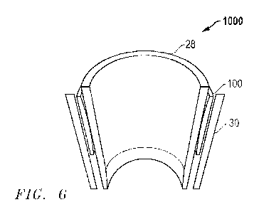
FIG. 6 shows a side view illustrating a finished bearing 100 within an
assembly 1000 according to a number of embodiments. The assembly 1000 may
further include an inner member 28 and an outer member 30. At least one of the
inner
member or the outer member 30 may include a shaft, rod, or tube. The outer
member
may include a housing within an assembly. As shown in FIG. 6, the bearing 100
is
disposed between the inner member 28 and the outer member 30.
In an embodiment, the inner member 28 can include any material commonly
used in the sliding assembly arts. The inner component 28 can include any
suitable
30 material with sufficient rigidity to withstand axial and longitudinal
forces. In a
particular embodiment, the inner member 28 can include a polymer. In another
embodiment, the inner member 28 can include a metal or alloy (such as, but not
limited to, aluminum, zinc, copper, magnesium, tin, titanium, tungsten, iron,
bronze,
- 12-
CA 03132376 2021-09-01
WO 2020/197908
PCT/US2020/023489
steel, spring steel, stainless steel). The inner member 28 can be formed from
a single
piece, two pieces, or several pieces joined together by welding, adhesive,
fasteners,
threading, or any other suitable fastening means.
In an embodiment, the outer member 30 can include any material commonly
used in the sliding assembly arts. The outer member 30 can include any
suitable
material with sufficient rigidity to withstand axial and longitudinal forces.
In a
particular embodiment, the outer member 30 can include a polymer. In another
embodiment, the outer member 30 can include a metal or alloy (such as, but not
limited to, aluminum, zinc, copper, magnesium, tin, titanium, tungsten, iron,
bronze,
steel, spring steel, stainless steel). The outer member 30 can be formed from
a single
piece, two pieces, or several pieces joined together by welding, adhesive,
fasteners,
threading, or any other suitable fastening means.
In an embodiment, the bearing 100 may translate in unison with at least one of
the inner member 28 and the outer member 30. For example, the bearing 100 may
be
positionally fixed to the outer member 30, and the inner member 28 may
translate
longitudinally relative to the outer member 30 and the bearing 100.
Alternatively, the
bearing 100 may be positionally fixed to the inner member 28, and the outer
member
30 may translate longitudinally relative to the inner member 28and the bearing
100.
In an embodiment, at least one of the inner member 28 or the outer member 30
may be adapted to axially translate relative to the bearing 100 at least 2.5%
of the
axial length, L, of the bearing 100, such as at least 5% of the axial length,
Lõsuch as
at least 7.5% of the axial length, L, such as at least 10% of the axial
length, L, such as
at least 15% of the axial length, L, such as at least 20% of the axial length,
L, such as
at least 25% of the axial length, L, such as at least 30% of the axial length,
L, such as
at least 40% of the axial length, L, such as at least 50% of the axial length,
L, such as
at least 60% of the axial length, L, such as at least 70% of the axial length,
L, such as
at least 80% of the axial length, L, such as at least 90% of the axial length,
L, or such
as at least 100% of the axial length, L. In a number of embodiments, at least
one of
the inner member 28 or the outer member 30 may be adapted to axially translate
relative to the bearing 100 at least 0.01 mm, such as at least 0.05 mm, at
least 0.1 mm,
at least 0.15 mm, at least 0.2 mm, at least 0.25 mm, at least 0.3 mm, at least
0.5 mm,
or at least 1 mm. In a number of embodiments, at least one of the inner member
28 or
the outer member 30 may be adapted to axially translate relative to the
bearing 100 no
- 13 -
CA 03132376 2021-09-01
WO 2020/197908
PCT/US2020/023489
greater than 500 mm, such as no greater than 400 mm, no greater than 300 mm,
no
greater than 200 mm, no greater than 150 mm, no greater than 100 mm, no
greater
than 50 mm, no greater than 25 mm, or no greater than 10 mm.
FIG. 7 shows a close up view illustrating the first convex axial end 120 of a
finished bearing 100 within an assembly 1000 according to a number of
embodiments. In a number of embodiments, at least one of the first convex
axial end
120 or the second convex axial end 130 of the bearing 100 may be continuously
convex. As used herein "continuously convex" may be defined as continuously
increasing in slope asymptotically tangent from either the first axial end 103
or the
second axial end 105 of the bearing 100 toward the flat portion 110
respectively. At
least one of the first convex axial end 120 or the second convex axial end 130
of the
bearing 100 may have a radius of curvature of at least 0.05 mm, such as at
least 0.1
mm, at least 0.15 mm, at least 0.25 mm, at least 0.5 mm, at least 1 mm, at
least 5 mm,
at least 15 mm, at least 25 mm, at least 50 mm, at least 100 mm, at least 250
mm, at
least 500 mm, or at least 100 mm. In a number of embodiments, at least one of
the
first convex axial end 120 or the second convex axial end 130 of the bearing
sidewall
102 or bearing 100 may be formed by at least one of chamfering, turning,
reaming,
forging, extruding, molding, sintering, rolling, or casting.
In at least one embodiment, the assembly 1000 may include a film 55 in the
form of lubricant on any of its components. In at least one embodiment, the
lubricant
may include a grease including at least one of lithium soap, lithium
disulfide,
graphite, mineral or vegetable oil, silicone grease, fluorether-based grease,
apiezon,
food-grade grease, petrochemical grease, or may be a different type. In at
least one
embodiment, the lubricant may include an oil including at least one of a Group
I-
GroupIII+ oil, paraffinic oil, naphthenic oil, aromatic oil, biolubricant,
castor oil,
canola oil, palm oil, sunflower seed oil, rapeseed oil, tall oil, lanolin,
synthetic oil,
polyalpha-olefin, synthetic ester, polyalkylene glycol, phosphate ester,
alkylated
naphthalene, silicate ester, ionic fluid, multiply alkylated cyclopentane,
petrochemical
based oil, or may be a different type. In at least one embodiment, the
lubricant may
include a solid based lubricant including at least one of lithium soap,
graphite, boron
nitride, molybdenum disulfide, tungsten disulfide, polytetrafluoroethylene, a
metal, a
metal alloy, or may be a different type.
- 14 -
CA 03132376 2021-09-01
WO 2020/197908
PCT/US2020/023489
In a number of embodiments, the axial translation of at least one of the inner
member 28 or the outer member 30 relative to the bearing 100 may induce
formation
of a film 55 on the bearing sidewall 102 during the axial translation of at
least one of
the inner member 28 or the outer member 30. This may result from at least one
of the
first convex axial end 120 or the second convex axial end 130 of the bearing
100
inducing the formation of the film 55. In a number of embodiments at least one
of the
first convex axial end 120 or the second convex axial end 130 of the bearing
100 may
induce the formation of the film 55 on the flat portion 110 of the bearing
sidewall 102
of the bearing 100. The induction of fluid film 55 may take place during axial
translation of at least one of the inner member 28 or the outer member 30
during
movement between the components. The induction of fluid film 55 may take place
during axial translation of at least one of the inner member 28 or the outer
member 30
during oscillatory or cyclic movement between the components. The induction of
fluid film 55 may take place as the lubricant may be pulled inwards from
axially
proximate components in the assembly 1000 into proximity with at least one of
the
convex axial end 120 and the second convex axial end 130 of the bearing 100
during
axial translation of at least one of the inner member 28 or the outer member
30, where
the film 55 propagates in the flat portion 110 of the bearing. As the inner or
outer
member 28, 30 translates relative to the bearing 100, lubricant 55 may be
drawn into
the flat portion 110 of the bearing 100 along either the first convex axial
end 120 or
the second convex axial end 130. Referring back to FIGs. 5A-5B, a viscous
wedge
may form proximal to the point at which the flat portion 110 meets either the
first
convex axial end 120 or the second convex axial end 130. The viscous wedge
allows
for fluid film 55 to develop between the bearing surface R1, R2 and
translating inner
component 28 or outer component 30. Either the first convex axial end 120 or
second
axial end 130 may be tangent to the flat portion 110 at the point at which the
flat
portion 110 meets either the first convex axial end 120 or the second convex
axial end
130.
FIG. 8 illustrates an assembly 1000 in the form of a suspension assembly for a
vehicle. In this non-limiting embodiment, the assembly 1000 is an exemplary
front
fork shock absorber suspension assembly for a two-wheeled vehicle, such as a
motorcycle or bicycle. In the assembly 1000, a steerer 802 may be paired with
a
crown 804 that can house two inner stanchions 806, 808 (or inner member 28 as
- 15 -
CA 03132376 2021-09-01
WO 2020/197908
PCT/US2020/023489
described herein). The inner stanchions 806, 808 may pair with the crown 804
via a
pair of top caps 810, 812. Two sliders 816, 818 can be placed over the inner
stanchions 806, 808 through a head tube 804 (or outer member 30 as described
herein). The sliders 816, 818 may be connected by an arch 820. Bearings 822,
824
can be placed between the inner stanchions 806, 808 and the sliders 816, 818
to
maintain alignment and prevent contact between the inner stanchions 806, 808
and the
sliders 816, 818. Bearings 800 and 824 can be substantially the same as
bearings 100,
as previously described. Optionally, a boot 830 may be placed over one of the
inner
stanchions 806, 808 to prevent contamination of the sliding surface of the
bearing 100
by dirt and other particulate matter, and/or aid in providing a damping
effect.
Alternatively, the bearing 100 may be used in an assembly 1000 for another
suspension component.
FIG. 9 illustrates a graph of time versus the dynamic friction force in the
axial
direction of a bearing in comparison to existing prior art bearings according
to a
number of embodiments. Bearing P1 is a known prior art bearing. Bearing P2 is
a
known prior art bearing. Bearing TR1 is a bearing 100 according to embodiments
shown herein. As shown, embodiments of bearings 100 shown herein have improved
(reduced) dynamic friction performance when compared to bearings known in the
art
due to the convex axial end of the bearings 100.
Various embodiments disclosed here can have significant advantages over
conventional solutions. According to embodiments herein, bearings with
improved
dynamic friction performance and stick-slip characteristics are provided.
Further,
various bearing embodiments exhibit improved stabilization between the other
components of the assembly. Further, according to embodiments herein, the
various
bearings may offer simple installation and retrofit existing assemblies.
Further, use of
a low friction layer on the bearing may significantly reduce friction between
the inner
and outer components during translation. Bearings of various embodiments may
further provide improved sliding force control when used between mating
components. The bearings of the various embodiments herein may reduce or
eliminate undesirable characteristics, such as vibration, stick-slip, and
friction within
components of a vehicle suspension.
Many different aspects and embodiments are possible. Some of those aspects
and embodiments are described below. After reading this specification, skilled
- 16-
CA 03132376 2021-09-01
WO 2020/197908
PCT/US2020/023489
artisans will appreciate that those aspects and embodiments are only
illustrative and
do not limit the scope of the present invention. Embodiments may be in
accordance
with any one or more of the embodiments as listed below.
Embodiment 1. An assembly comprising: an inner member; an outer member;
and a bearing comprising a bearing sidewall comprising a flat portion, a first
convex
axial end, and a second convex axial end, wherein at least one of the inner
member or
the outer member is adapted to axially translate relative to the bearing and
wherein at
least one of the first convex axial end or the second convex axial end is
adapted to
induce formation of a film on the bearing sidewall during the axial
translation of at
least one of the inner member or the outer member.
Embodiment 2. A method comprising: providing an inner member; providing
an outer member; providing a bearing disposed between the inner member and the
outer member, the bearing comprising a bearing sidewall comprising a flat
portion, a
first convex axial end, and a second convex axial end; and axially translating
at least
one of the inner member or the outer member relative to the bearing to induce
formation of a film on the bearing sidewall.
Embodiment 3. The assembly or method of any of the preceding
embodiments, wherein at least one of the first convex axial end or the second
convex
axial end is continuously convex.
Embodiment 4. The assembly or method of any of the preceding
embodiments, wherein at least one of the first convex axial end or the second
convex
axial end has a radius of curvature of at least 0.05 mm.
Embodiment 5. The assembly or method of any of the preceding
embodiments, wherein the bearing comprises a substrate.
Embodiment 6. The assembly or method of embodiment 5, wherein the
substrate comprises a plastic, a metal, or a ceramic.
Embodiment 7. The assembly or method of embodiment 5, wherein the
substrate comprises steel or stainless steel.
Embodiment 8. The assembly or method of embodiment 5, wherein the
bearing further includes a low friction layer overlying the substrate.
Embodiment 9. The assembly or method of embodiment 8, wherein the low
friction layer comprises a polyketone, polyaramid, a thermoplastic polyimide,
a
polyetherimide, a polyphenylene sulfide, a polyethersulfone, a polysulfone, a
- 17 -
CA 03132376 2021-09-01
WO 2020/197908
PCT/US2020/023489
polyphenylene sulfone, a polyamideimide, ultra high molecular weight
polyethylene,
a thermoplastic fluoropolymer, a polyamide, a polybenzimidazole, or any
combination thereof.
Embodiment 10. The assembly or method of embodiment 8, wherein the low
friction layer comprises a fluoropolymer.
Embodiment 11. The assembly or method of any of embodiments 5-10,
wherein the bearing further comprises an adhesive layer between the substrate
and the
low friction layer.
Embodiment 12. The assembly or method of embodiment 11, wherein the
adhesive layer comprises epoxy resins, polyimide resins, polyether/polyamide
copolymers, ethylene vinyl acetates, ETFE copolymer, or any combination
thereof.
Embodiment 13. The assembly or method of any of the preceding
embodiments, wherein the film comprises a lubricant comprising at least one of
water,
a grease, or an oil.
Embodiment 14. The assembly or method of any of the preceding
embodiments, wherein the assembly is a suspension assembly for a vehicle.
Embodiment 15. The assembly or method of any of the preceding
embodiments, wherein bearing comprises an axial gap.
Embodiment 16. The assembly or method of any of the preceding
embodiments, wherein the formation of the film is induced on the flat portion
of the
bearing sidew all.
Embodiment 17. The assembly or method of any of the preceding
embodiments, wherein at least one of the first convex axial end or the second
convex
axial end of the bearing is formed by at least one of chamfering, turning,
reaming,
forging, extruding, molding, sintering, rolling, or casting.
Embodiment 18. The assembly or method of any of the preceding
embodiments, wherein at least one of the inner member or the outer member is a
rod,
shaft, or tube within a bicycle assembly.
Embodiment 19. The assembly or method of any of the preceding
embodiments, wherein the length, L, is between about 5 to 100 mm.
Embodiment 20. The assembly or method of any of the preceding
embodiments, wherein the bearing has an outer radius, IR, between about 5 to
25 mm.
- 18 -
CA 03132376 2021-09-01
WO 2020/197908
PCT/US2020/023489
Note that not all of the features described above are required, that a portion
of
a specific feature may not be required, and that one or more features may be
provided
in addition to those described. Still further, the order in which features are
described
is not necessarily the order in which the features are installed.
Certain features are, for clarity, described herein in the context of separate
embodiments, may also be provided in combination in a single embodiment.
Conversely, various features that are, for brevity, described in the context
of a single
embodiment, may also be provided separately or in any subcombinations.
Benefits, other advantages, and solutions to problems have been described
above with regard to specific embodiments, However, the benefits, advantages,
solutions to problems, and any feature(s) that may cause any benefit,
advantage, or
solution to occur or become more pronounced are not to be construed as a
critical,
required, or essential feature of any or all the claims.
The specification and illustrations of the embodiments described herein are
intended to provide a general understanding of the structure of the various
embodiments. The specification and illustrations are not intended to serve as
an
exhaustive and comprehensive description of all of the elements and features
of
apparatus and systems that use the structures or methods described herein.
Separate
embodiments may also be provided in combination in a single embodiment, and
conversely, various features that are, for brevity, described in the context
of a single
embodiment, may also be provided separately or in any subcombination. Further,
reference to values stated in ranges includes each and every value within that
range.
Many other embodiments may be apparent to skilled artisans only after reading
this
specification. Other embodiments may be used and derived from the disclosure,
such
that a structural substitution, logical substitution, or any change may be
made without
departing from the scope of the disclosure. Accordingly, the disclosure is to
be
regarded as illustrative rather than restrictive.
- 19-