Note: Descriptions are shown in the official language in which they were submitted.
CA 03133492 2021-09-14
HEAT INSULATING CONTAINER
BACKGROUND OF THE INVENTION
Technical Field
The present disclosure is related to a food container, and in particular to an
anti-scald heat
insulating container.
Description of Related Art
Generally, foods are contained in a container and placed in a microwave oven
when the
foods are heated by the microwave oven. The container cannot be heated by
microwave because
it contains no water, but heat still could be transferred to the entire
container from the heated
food. A user must wait until the container is cooled after the container is
heated and then the
container could be taken out. Therefore, it is inconvenient, and the foods are
cooled while the
container is cooled.
In views of this, in order to solve the above disadvantage, the present
inventor studied
related technology and provided a reasonable and effective solution in the
present disclosure.
SUMMARY OF THE INVENTION
An anti-scald heat insulating container is provided in the present disclosure.
A heat insulating container having a bottom box and a surrounding wall
surrounding the
bottom box is provided in the present disclosure. A top portion of the bottom
box is open and
connected with the surrounding wall, an inner space of the surrounding wall is
connected with
an inner space of the bottom box, an opening is defined by a top edge of the
surrounding wall,
a handle portion is downward extended from an external surface of a junction
between the
bottom box and the surrounding wall, the handle portion and the bottom box are
arranged at
interval, and the handle portion is wrapped by a rubber strip.
According to the heat insulating container of the present disclosure, the
opening is covered
by a lid, a rubber strip is arranged on the lid, and the rubber strip is
clamped between the lid
and the surrounding wall and the opening is thereby sealed. A positioning
recess is defined on
1
Date Recue/Date Received 2021-09-14
CA 03133492 2021-09-14
an external surface of the lid, and the positioning recess is shaped
corresponding to an external
bottom surface of the bottom box for accommodating another bottom box. An
annular groove
is defined on a surface of the lid and a through hole is defined on the lid,
the through hole is
connected with the annular groove, the rubber strip is embedded in the annular
groove and a
portion of the rubber strip is embedded in the through hole.
According to the heat insulating container of the present disclosure, a
plurality of snap-fits
is arranged on an edge of the lid, the respective snap-fits buckle on an
external surface of the
surrounding wall. At least one barb for buckling with the snap-fits is
arranged on the external
surface of the surrounding wall. The barb is extended to surround the opening.
According to the heat insulating container of the present disclosure, a recess
is formed on
an external bottom surface of the bottom box. A flange is outward extended
from a junction
between the bottom box and the surrounding wall, and the flange is connected
between the
bottom box and the surrounding wall. An inner box is accommodated in the
surrounding wall
and the inner box is stacked on the flange of the bottom box. The handle
portion is extended
from a lower edge of the surrounding wall.
According to the heat insulating container of the present disclosure, the
handle portion of
the surrounding wall and the bottom box are arranged at interval, and a space
barrier is thereby
defined to prevent a user from being scalded by directly contact with the
bottom box.
BRIEF DESCRIPTION OF DRAWINGS
The present disclosure can be more fully understood by reading the following
detailed
description of the embodiment, with reference made to the accompanying
drawings as follows:
Fig. 1 is an exploded view showing the heat insulating container according to
a preferred
embodiment of the present disclosure.
Fig. 2 is a perspective view showing the heat insulating container according
to the
preferred embodiment of the present disclosure.
Fig. 3 is an exploded view showing the heat insulating container and a lid
thereof according
2
Date Recue/Date Received 2021-09-14
CA 03133492 2021-09-14
to the preferred embodiment of the present disclosure.
Fig. 4 is an exploded view showing the lid of the heat insulating container
according to the
preferred embodiment of the present disclosure.
Fig. 5 is a perspective view showing the heat insulating container and the lid
thereof
according to the preferred embodiment of the present disclosure.
Fig. 6 is a cross-sectional view of the heat insulating container and the lid
thereof according
to the preferred embodiment of the present disclosure.
Fig. 7 is a schematic view showing the stacked heat insulating containers
according to the
preferred embodiment of the present disclosure.
Figs. 8 to 11 are schematic views showing various types of the nested heat
insulating
containers according to the preferred embodiment of the present disclosure.
Fig. 12 is a schematic view showing alternative type of the junction between
the bottom
box and the surrounding wall of the heat insulating container.
DETAILED DESCRIPTION OF THE INVENTION
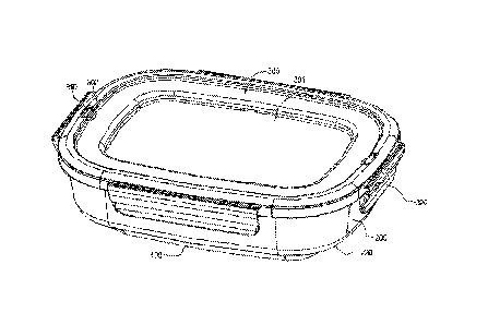
According to Figs. 1 to 6, an anti-scald heat insulating container is provided
in an
embodiment of the present disclosure. The heat insulating container at least
has a bottom box
100 and a surrounding wall 200. An opening 201 is enclosed by a top edge of
the surrounding
wall 200, and a handle portion 202 is downward extended from an external
surface of a junction
103 between the bottom box 100 and the surrounding wall 200.
According to the present embodiment, the bottom box 100 is preferably a flat
cubic, a top
101 of the bottom box 100 is open and connected with the surrounding wall 200.
According to
the present embodiment, a flange 110 is outward extended from the bottom box
100 at the
junction 103 between the bottom box 100 and the surrounding wall 200.
Specifically, the flange
110 outward protrudes from the top 101 of the bottom box 100, and the flange
110 is extended
to surround the top 101 of the bottom box 100 and connected with the
surrounding wall 200.
However, scopes of the present disclosure should not be limited to the
embodiment, the
3
Date Recue/Date Received 2021-09-14
CA 03133492 2021-09-14
surrounding wall 200 could alternatively be an inverted cone directly
connected with the top
101 of the bottom box 100.
Specifically, the surrounding wall 200 surrounds the top 101 of the bottom box
100, an
external edge of the flange 110 is connected with and internal surface of the
surrounding wall
200, an inner space of the surrounding wall 200 is thereby connected with an
inner space of the
bottom box 100 for accommodating foods therein. According to the present
embodiment, the
handle portion 202 is preferably downward extended from a lower edge of the
surrounding wall
200. The handle portion 202 protrudes the flange 110, the handle portion 202
and the bottom
box 100 are arranged at interval, and the handle portion 202 is wrapped by a
rubber strip 220
for heat insulation.
According to the heat insulating container of the present disclosure, the
handle portion 202
of the surrounding wall 200 and the bottom box 100 are arranged at interval to
form a space
barrier and to prevent the bottom box 100 from directly contacting with a
user. Furthermore,
the handle portion 202 is wrapped by the rubber strip 220 to prevent from
scald when the user
holds the handle portion 202. Moreover, the foods are usually not completely
filled in the heat
insulating container, and the top edge of the surrounding wall 200 is thereby
prevented from
contacting with the heated foods and is therefore not hot. Accordingly, the
heat insulating
container of the present disclosure could be immediately taken out of a
microwave oven after
being heated, because the user will not be scalded when handles the top edge
of the surrounding
wall 200 and the handle portion 202 heat insulating container.
The opening 201 could be covered by a lid 300, and detail structures of the
lid 300 are
described below. According to the present embodiment, the lid 300 is
preferably a rectangular
plate, the lid 300 is wrapped by a rubber strip 310, the rubber strip 310 is
clamped between the
lid 300 and the surrounding wall 200 and the opening 201 is thereby sealed.
Furthermore, the
rubber strip 310 could further block heat transfer between the lid 300 and the
surrounding wall
200 for further heat insulation. Accordingly, when the opening 201 is covered
by the lid 300,
4
Date Recue/Date Received 2021-09-14
CA 03133492 2021-09-14
the user will not be scalded when handles the lid 300 and the handle portion
202 of the
surrounding wall 200.
Specifically, an annular groove 321 is defined on a surface of the lid 300 and
a through
hole 302 is defined on the lid 300, the through hole 302 is connected to the
annular groove 321,
the rubber strip 310 is embedded in the annular groove 321 and a portion of
the rubber strip 310
is embedded in the through hole 302. The annular groove 321 is shaped
corresponding to the
opening 201 on the top edge of the surrounding wall 200, the through hole 302
of the lid 300
could be an inlet channel for modeling the rubber strip 310. Thereby, a
material could be
injected into the annular groove 321 through the through hole 302 to form the
rubber strip 310
in the annular groove 321.
A plurality of snap-fits 320 are arranged on an edge of the lid 300, the
respective snap-fits
320 buckle on an external surface of the surrounding wall 200 to press the lid
300 on the opening
201 and thereby sealing the opening 201. At least one barb 210 for buckling
with the snap-fits
320 is arranged on the external surface of the aforementioned surrounding wall
200 and adjacent
to the opening 201. However, the type of the barb 210 should not be limited to
the embodiment.
For example, a single barb 210 could be arranged surrounding the opening 201,
the respective
snap-fits 320 are buckled with the barb 210. Alternatively, a plurality of
barbs 210
corresponding to the respective snap-fits 320 could be arranged on the
surrounding wall 200
and outside of the opening 201, and the respective snap-fits 320 are buckled
with the respective
.. corresponding barbs 210.
According to the heat insulating container of the present disclosure, a recess
102 is formed
on an external bottom surface of the bottom box 100. When the heat insulating
container is
heated, the external bottom surface is separated from a plan where it is
placed by the recess 102
and a gap is formed therebetween. Thereby, the external bottom surface the
bottom box 100 is
prevented from sticking with the plane caused by vapor generated while
heating.
According to Fig. 7, preferably, a positioning recess 301 could be selectively
defined on
5
Date Recue/Date Received 2021-09-14
CA 03133492 2021-09-14
an external surface of the lid 300, the positioning recess 301 is shaped
corresponding to the
external bottom surface of the bottom box 100, when multiple heat insulating
containers
according to the present disclosure are arranged in a stack, another bottom
box 10 of another
heat insulating container could be accommodated in the positioning recess 301.
According to Fig. 8, an inner box 400 could be selectively accommodated in the
surrounding wall 200, and the inner box 400 is stacked on the flange 110 of
the bottom box 100.
Thereby, the inner space of the heat insulating container could be separated,
and different foods
could be respectively accommodated in the inner box 400 and the bottom box
100.
According to the heat insulating container of the present disclosure, the
surrounding wall
200 is insulated from the bottom box 100 by the flange 110, and the handle
portion 202 and the
bottom box 100 are arranged at interval, and the handle portion 202 is wrapped
by the rubber
strip 220. Thereby, the bottom box 100 is prevented from direct contacting
with the user, and
the heated heat insulating container could be immediately taken out of the
microwave oven.
According to Figs. 9 to 11, multiple heat insulating containers of the present
disclosure
with various sizes could be nested with each other. The nested heat insulating
containers could
be fixed with each other by various structures. According to Fig. 9, The
bottom box 100 of the
accommodated heat insulating container is stacked on an internal bottom of the
bottom box 20
outside thereof, the handle portion 202 of the accommodated heat insulating
container presses
on an internal surface of the bottom box 20 outside thereof, and the heat
insulating containers
are thereby prevented from relative shifting. According to Fig. 10, the bottom
box 100 of the
accommodated heat insulating container stacked on the internal surface of the
bottom box 20
outside thereof, the latch 320 of the lid 300 of the accommodated heat
insulating container
presses the internal surface of the surrounding wall 30 outside thereof, and
the heat insulating
containers are thereby prevented from relative shift. According to Fig. 11,
the handle portion
202 of the accommodated heat insulating container supports on the flange 11 of
the heat
insulating container outside thereof, and the bottom box 100/20 nested with
each other are
6
Date Recue/Date Received 2021-09-14
CA 03133492 2021-09-14
thereby separated from each other.
The junction 103 between the bottom box 100 and the surrounding wall 200 of
the present
disclosure should not be limited to be the aforementioned flange 110.
Alternatively, the bottom
box 100 and the surrounding wall 200 could be smoothly connected at the
junction 103 as
shown in Fig. 12.
According to the heat insulating container of the embodiment of the present
application,
the handle portion of the surrounding wall and the bottom box are arranged at
interval, and a
space barrier is thereby defined therebetween to prevent the bottom box from
direct contacting
with the user and scald is therefore avoided. Accordingly, the present
disclosure can be applied
in industries.
Although the present disclosure has been described with reference to the
foregoing
preferred embodiment, it will be understood that the disclosure is not limited
to the details
thereof. Various equivalent variations and modifications can still occur to
those skilled in this
art in view of the teachings of the present disclosure. Thus, all such
variations and equivalent
modifications are also embraced within the scope of the present disclosure as
defined in the
appended claims.
7
Date Recue/Date Received 2021-09-14