Language selection

Search

Patent 3134104 Summary

Third-party information liability

Some of the information on this Web page has been provided by external sources. The Government of Canada is not responsible for the accuracy, reliability or currency of the information supplied by external sources. Users wishing to rely upon this information should consult directly with the source of the information. Content provided by external sources is not subject to official languages, privacy and accessibility requirements.

Claims and Abstract availability

Any discrepancies in the text and image of the Claims and Abstract are due to differing posting times. Text of the Claims and Abstract are posted:

  • At the time the application is open to public inspection;
  • At the time of issue of the patent (grant).
(12) Patent Application: (11) CA 3134104
(54) English Title: METHOD AND DEVICE IN A FLOOR STRUCTURE DRYING PROCESS
(54) French Title: PROCEDE ET DISPOSITIF DANS UN PROCESSUS DE SECHAGE DE STRUCTURE DE PLANCHER
Status: Examination
Bibliographic Data
(51) International Patent Classification (IPC):
  • E04B 1/70 (2006.01)
  • E04G 23/02 (2006.01)
  • F26B 9/02 (2006.01)
(72) Inventors :
  • AHSBERG, JOHAN (Sweden)
(73) Owners :
  • REDDO FLOOR SOLUTIONS AB
(71) Applicants :
  • REDDO FLOOR SOLUTIONS AB (Sweden)
(74) Agent: SMART & BIGGAR LP
(74) Associate agent:
(45) Issued:
(86) PCT Filing Date: 2020-04-08
(87) Open to Public Inspection: 2020-10-15
Examination requested: 2024-04-04
Availability of licence: N/A
Dedicated to the Public: N/A
(25) Language of filing: English

Patent Cooperation Treaty (PCT): Yes
(86) PCT Filing Number: PCT/SE2020/050365
(87) International Publication Number: WO 2020209779
(85) National Entry: 2021-09-17

(30) Application Priority Data:
Application No. Country/Territory Date
1930117-5 (Sweden) 2019-04-09

Abstracts

English Abstract

A method and device for holding a subsurface layer (34) of an elevated flooring portion of a floor structure at a distance (D) from a subfloor (36) in a vicinity of an opening in the flooring portion during a process of drying the floor structure. According to the invention there is provided at least one rod (10) having a substantially perpendicularly angled end (18). The rod (10) is inserted below the subsurface layer (34) through the opening and the angled end (18) of the rod (10) is attached to an edge of a surface layer (32) in the opening of the flooring portion in a manner that the rod (10) supports the subsurface layer at said distance from the subfloor (36) when the flooring portion (30) is elevated.


French Abstract

L'invention concerne un procédé et un dispositif de maintien d'une couche de sous-sol (34) d'une partie de revêtement de sol élevée d'une structure de plancher à une distance (D) d'un sous-plancher (36) à proximité d'une ouverture dans la partie de revêtement de sol pendant un processus de séchage de la structure de plancher. Selon l'invention, il est prévu au moins une tige (10) ayant une extrémité inclinée (18) sensiblement perpendiculaire. La tige (10) est insérée sous la couche de sous-sol (34) à travers l'ouverture et l'extrémité inclinée (18) de la tige (10) est fixée à un bord d'une couche de surface (32) dans l'ouverture de la partie de revêtement de sol de telle sorte que la tige (10) supporte la couche de sous-sol à ladite distance du sous-plancher (36) lorsque la partie de revêtement de sol (30) est élevée.

Claims

Note: Claims are shown in the official language in which they were submitted.

CA 03134104 2021-09-17
WO 2020/209779 5
PCT/SE2020/050365
Claims
1. A method of holding a subsurface layer (34) of an elevated flooring portion
(30) of a floor structure at a
distance (D) from a subfloor (36) in a vicinity of an opening in the flooring
portion during a process of dry-
ing the floor structure, characterized by
providing a rod (10) having a substantially perpendicularly angled end (18);
inserting the rod (10) below the subsurface layer (34) through the opening;
and
attaching the angled end (18) of the rod (10) to an edge of a surface layer
(32) in the opening of the floor-
ing portion in a manner that the rod (10) supports the subsurface layer at
said distance (D) from the sub-
floor (36) when the flooring portion (30) is elevated.
2. The method of claim 1, comprised by the attaching is by releasable
fasteners (22).
3. The method of claim 1 or 2, comprised by the attaching is by screwing.
4. The method of any of claims 1-3, comprised by making the distance (D) from
the subfloor (36) to the
subsurface layer(34) larger than a distance (d) from the subsurface layer (34)
to the surface layer (32) of
the floor structure.
5. The method of any of claims 1-4, comprised by the distance (D) from the
subfloor (36) to the subsur-
face layer (34) is an average distance due to a flexible nature of the
subsurface layer.
6. The method of claim 5, comprised by making said distance (D) from the
subfloor (36) to the subsurface
layer (34) more than twice the distance (d) from the subsurface layer (34) to
the surface layer (32).
.. 7. A device for holding a subsurface layer (34) of an elevated flooring
portion (30) of a floor structure at a
distance (D) from a subfloor (36) in a vicinity of an opening in the flooring
portion (30) during a process of
drying the floor structure, characterized by
a rod (10) having a substantially perpendicularly angled end (18) to be
attached to an edge of a surface
layer (32) in the opening of the flooring portion in a manner that the rod
(10) supports the subsurface
layer (34) at said distance (D) from the subfloor (36) when the flooring
portion (30) is elevated.
8. The device of claim 7, wherein the angled end (18) has an aperture (20) for
attachment to the edge of
the surface layer (32) by a releasable fastener (22).
9. The device of claim 7 or 8, wherein the rod (10) has a flattened main
portion (12).
10. The device of claim 9, wherein a face of the flattened main portion (12)
is provided with a stiffening
ridge (14).

CA 03134104 2021-09-17
WO 2020/209779 6
PCT/SE2020/050365
11. The device of any of claims 7-10, wherein the rod (10) has a tapered
forward portion (16).

Description

Note: Descriptions are shown in the official language in which they were submitted.


CA 03134104 2021-09-17
WO 2020/209779 1
PCT/SE2020/050365
METHOD AND DEVICE IN A FLOOR STRUCTURE DRYING PROCESS
Technical area
This invention relates to a method of holding a subsurface layer of an
elevated flooring portion in a floor
structure at a distance from a subfloor in a vicinity of an opening in the
flooring portion during a process
of drying the floor structure.
Background
When drying a floor structure using an elevated flooring portion including a
flexible subsurface layer, as
disclosed in US 10,106,977, there is a likelihood that the surfaces in the
floor structure below and above
the subsurface layer will either be too dry or not properly dried unless
measures are taken in this regard.
More precisely, if the subfloor surface below the subsurface layer is not
sufficiently dried when the sub-
surface layer is resting on a subfloor, microbial growth may occur, and if the
drying process then is en-
hanced to sufficiently dry that surface, the surface layer above may instead
be damaged by overdrying.
To overcome this problem, said US 10,106,977 suggests that the subsurface
layer is intermittently at-
tached at patches to the bottom of the surface layer in vicinity of the
opening, so that the drying airflow
will also enter a ventilating space above the subsurface layer, in addition to
the ventilating space below
the subsurface layer. This measure, however, has shown to be cumbersome and
unreliable.
Disclosure of the invention
An object invention is to provide a method and device that eliminates the
above mentioned problems in
the prior art of drying an elevated flooring portion having a subsurface
layer.
In an aspect of the invention the method is further comprised by
providing a rod having a substantially perpendicularly angled end;
inserting the rod below the subsurface layer through the opening; and
attaching the angled end of the rod to an edge of a surface layer in the
opening of the flooring portion in
a manner that the rod supports the subsurface layer at said distance from the
subfloor when the floor-
ing portion is elevated.
Thereby two air gaps will be exposed in the opening when dry air is forced
into the opening in the floor-
ing. Accordingly, the dry air will flow along the floor structure both below
and above the subsurface lay-
er.
The attaching of the angled end to the edge of the surface layer may be
performed by releasable fas-
teners such as screws.

CA 03134104 2021-09-17
WO 2020/209779 2
PCT/SE2020/050365
By making the distance from the subfloor to the subsurface layer larger than a
distance from the subsur-
face layer to the surface layer of the floor structure, more dry air will flow
below than above the subsur-
face layer so that the surface layer can be prevented from being overdried
before the subfloor is suffi-
ciently dried.
The distance from the subfloor to the subsurface layer may be an average
distance due to a flexible na-
ture of the subsurface layer. More precisely, as the subsurface layer is often
flexible, it will depend in ar-
eas outside the rod (or between rods when, for example four rods are attached
in the opening). In that
case the subsurface layer may even be clamped against the surface layer at
least by a forward tip of the
rod(s).
Specifically, the distance from the subfloor to the subsurface layer may be
more than twice the distance
from the subsurface layer to the surface layer.
Other features and advantages of the invention are apparent from the detailed
description and the ap-
pended claims.
Brief description of the drawing
FIG. 1 is an oblique view of a device according to the invention;
FIG. 2 is a partial perspective view showing a device of FIG. 1 during
insertion in the flooring;
FIG. 3 is a view corresponding to FIG.2 showing four devices being inserted in
an elevated flooring and
attached to a surface layer of the flooring;
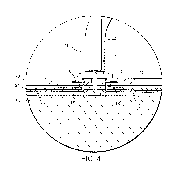
FIG.4 is a partial section view showing a pair of devices according to the
invention attached to an elevat-
ed flooring surface layer during a drying process; and
FIG.5 is a partial section view of an alternative embodiment of a device
according to the invention.
Detailed description of embodiments
The device according to the invention shown in FIG. 1 comprises a rod 10
having an elongated main por-
tion 12 and a substantially perpendicularly angled end 18. In the exemplary
embodiment shown, the
main portion 12 has a flattened shape and is on a top face provided with one
or more stiffening ridges
14 extending to a tapered forward portion 16 for facilitating insertion yet to
be described. The rod 10
may typically have a length of about 30 centimeters and be made of any
suitable durable and relatively
stiff and resilient material such a synthetic resin or a formed metallic sheet
material.
The angled end 18 has an aperture or a screw hole 20 therethrough for
attaching the rod 10 by a screw
22 to an edge of a closed opening in a flooring 30 as illustrated in FIGS. 3
and 4.

CA 03134104 2021-09-17
WO 2020/209779 3
PCT/SE2020/050365
FIG. 2 shows a rod 10 being inserted in the closed opening that cut out from
the flooring 30, for example
by sawing. In the exemplary embodiment shown, the flooring 30 has a stiff
surface layer 32, such as a
wooden parquet layer, and a flexible subsurface layer 34, such as a step sound
attenuating foam layer or
a damp proofing sheet layer. The flooring 30 is resting on a subfloor 36 that
may be of various types, for
example a concrete subfloor. To facilitate insertion of the rod 10 below the
subsurface layer 34, the sur-
face layer 32 is elevated by means, for example, of a small crowbar 24
inserted between the subsurface
layer 34 and the surface layer 32.
The surface layer is elevated so far that the angled end 18 of rod 10 may be
attached by screw 22 to a
center portion of an edge of the opening in the surface layer 32 as
illustrated in FIG. 3.
As further illustrated in FIG. 3, one or more additional rods 10 may be
attached in the same manner
around the opening in the surface layer 32. For explanatory purposes, FIG. 3
also shows the flooring 30
being further elevated to a level where the floor structure is being dried.
The subsurface layer 34 is then
supported by the rods 10 at an average distance d of typically about 5-25
millimeters from the surface
layer 32, whereby an average distance D between the subsurface layer 34 and
the subfloor may typically
be about 20-40 millimeters. These average distances are typically due to the
flexible nature of the sub-
surface layer 34 as diagrammatically illustrated by phantom lines in FIG. 3,
showing the subsurface layer
34 depending in areas between the rods 10.
As illustrated in FIG. 4, the flooring 30 is thus elevated by an adapter 10
attached to the surface layer in-
cluding an elevating device 42 for pushing the surface layer 32 away from the
subfloor 36. In the drying
process dry air is forced via tubing 44 through the opening in the flooring
and into the respective gaps or
ventilating spaces maintained above and below the subsurface layer 34 by the
rods 10.
As indicated in FIG. 5, which shows rear and forward portions of a formed thin
sheet metal embodiment
of a rod 10, to minimize weight and material, the rod may also be slightly
oriented or curved upwards
from the angled end 18 to the forward portion 16, for the resilient rod 10 to
keep the distance to the
subfloor when loaded by the weight of the subsurface layer 34. In all
embodiments of rods, the flexible
subsurface layer 34 may also abut the surface layer 32 close to the rod(s), at
least at the forward portion
16 of the rod(s) 10.
When the drying process is completed, the adapter 40 and the rods 10 are
removed, and the opening
may be sealed by a suitable lid (not shown) or by other means of restoring or
repairing the surface layer.
More details of the drying process are described in the above referenced prior
art document US
10,106,977.

CA 03134104 2021-09-17
WO 2020/209779 4 PCT/SE2020/050365
The foregoing detailed description is given primarily for clearness of
understanding and no unnecessary
limitations are to be understood therefrom. Modifications will become obvious
to those skilled in the art
upon reading this disclosure and may be made without departing from the scope
of the appended
claims.

Representative Drawing
A single figure which represents the drawing illustrating the invention.
Administrative Status

2024-08-01:As part of the Next Generation Patents (NGP) transition, the Canadian Patents Database (CPD) now contains a more detailed Event History, which replicates the Event Log of our new back-office solution.

Please note that "Inactive:" events refers to events no longer in use in our new back-office solution.

For a clearer understanding of the status of the application/patent presented on this page, the site Disclaimer , as well as the definitions for Patent , Event History , Maintenance Fee  and Payment History  should be consulted.

Event History

Description Date
Letter Sent 2024-04-08
Request for Examination Requirements Determined Compliant 2024-04-04
Request for Examination Received 2024-04-04
All Requirements for Examination Determined Compliant 2024-04-04
Maintenance Request Received 2024-03-12
Maintenance Request Received 2023-03-20
Inactive: Cover page published 2021-12-01
Letter sent 2021-10-19
Priority Claim Requirements Determined Compliant 2021-10-18
Application Received - PCT 2021-10-18
Inactive: First IPC assigned 2021-10-18
Inactive: IPC assigned 2021-10-18
Request for Priority Received 2021-10-18
National Entry Requirements Determined Compliant 2021-09-17
Application Published (Open to Public Inspection) 2020-10-15

Abandonment History

There is no abandonment history.

Maintenance Fee

The last payment was received on 2024-03-12

Note : If the full payment has not been received on or before the date indicated, a further fee may be required which may be one of the following

  • the reinstatement fee;
  • the late payment fee; or
  • additional fee to reverse deemed expiry.

Please refer to the CIPO Patent Fees web page to see all current fee amounts.

Fee History

Fee Type Anniversary Year Due Date Paid Date
Basic national fee - standard 2021-09-17 2021-09-17
MF (application, 2nd anniv.) - standard 02 2022-04-08 2022-04-05
MF (application, 3rd anniv.) - standard 03 2023-04-11 2023-03-20
MF (application, 4th anniv.) - standard 04 2024-04-08 2024-03-12
Request for examination - standard 2024-04-08 2024-04-04
Owners on Record

Note: Records showing the ownership history in alphabetical order.

Current Owners on Record
REDDO FLOOR SOLUTIONS AB
Past Owners on Record
JOHAN AHSBERG
Past Owners that do not appear in the "Owners on Record" listing will appear in other documentation within the application.
Documents

To view selected files, please enter reCAPTCHA code :


To view images, click a link in the Document Description column. To download the documents, select one or more checkboxes in the first column and then click the "Download Selected in PDF format (Zip Archive)" or the "Download Selected as Single PDF" button.

List of published and non-published patent-specific documents on the CPD .

If you have any difficulty accessing content, you can call the Client Service Centre at 1-866-997-1936 or send them an e-mail at CIPO Client Service Centre.


Document
Description 
Date
(yyyy-mm-dd) 
Number of pages   Size of Image (KB) 
Description 2021-09-17 4 146
Representative drawing 2021-09-17 1 35
Drawings 2021-09-17 3 105
Claims 2021-09-17 2 47
Abstract 2021-09-17 2 74
Cover Page 2021-12-01 1 54
Maintenance fee payment 2024-03-12 1 23
Request for examination 2024-04-04 5 137
Courtesy - Acknowledgement of Request for Examination 2024-04-08 1 443
Courtesy - Letter Acknowledging PCT National Phase Entry 2021-10-19 1 588
International search report 2021-09-17 4 104
National entry request 2021-09-17 6 182
Maintenance fee payment 2022-04-05 1 27
Maintenance fee payment 2023-03-20 1 23