Note: Descriptions are shown in the official language in which they were submitted.
CA 03134176 2021-09-17
WO 2020/214884 PCT/US2020/028629
ELECTRIC MOTOR
REFERENCE TO RELATED APPLICATIONS
[0001] This application claims priority to U.S. Patent Application No.
62/835,686
filed on April 18, 2019 and to U.S. Patent Application No. 62/935,879 filed on
November 15, 2019, the entirety of each of which is hereby incorporated by
reference.
FIELD
[0002] The present disclosure relates generally to electric motors, and more
particularly, to brushless electric motors with integrated brakes.
BACKGROUND
[0003] Many applications that utilize electric motors also utilize brakes.
Hence, there
are a multitude of inventions combining these two technologies. Designers of
electric motors
consider package size limitations, torque requirements, holding and
slowing/stopping
requirements, and other requirements when designing electric motors.
SUMMARY
[0004] In one example, an electric motor is described. The electric motor
includes a
housing, a stator fixed relative to the housing, a rotor, a brake assembly, a
first bearing, and a
second bearing. The rotor has a hub portion, a cylindrical portion, and a disk
portion. The
hub portion of the rotor has a first end, a second end, and a through hole
therethrough. The
brake assembly is fixed relative to the housing and configured to selectively
couple the disk
portion of the rotor to the housing. The first bearing is mounted between the
first end of the
hub portion of the rotor and the disk portion of the rotor. The second bearing
is mounted
between the second end of the hub portion of the rotor and the disk portion of
the rotor.
[0005] In another example, an electric motor is described. The electric motor
includes a housing, a stator fixed relative to the housing, a rotor, a brake
assembly, a first
bearing, and a second bearing. The rotor has a hub portion, a cylindrical
portion, and a disk
portion. The hub portion of the rotor has a first end, a second end, and a
through hole
therethrough. The brake assembly is fixed relative to the housing and has a
cylindrical
portion. In addition, the brake assembly is configured to selectively couple
the disk portion
of the rotor to the housing. The first bearing is mounted between the second
end of the hub
portion of the rotor and the disk portion of the rotor. The second bearing is
mounted between
the second end of the hub portion of the rotor and the disk portion of the
rotor. The first
1
CA 03134176 2021-09-17
WO 2020/214884 PCT/US2020/028629
bearing and the second bearing each have an outer diameter that is greater
than an inner
diameter of the cylindrical portion of the brake assembly. Also, the first
bearing and the
second bearing each have an inner diameter that is less than the inner
diameter of the
cylindrical portion of the brake assembly.
[0006] In another example, an electric motor is described. The electric motor
includes a housing, a stator fixed relative to the housing, a rotor, and a
brake assembly. The
rotor has a hub portion, a cylindrical portion, and a disk portion. The hub
portion of the rotor
has a first end, a second end, and a through hole therethrough. The brake
assembly is fixed
relative to the housing and is configured to selectively couple the disk
portion of the rotor to
the housing. In addition, the brake assembly includes a brake housing. The
brake housing
has a base, a first cylindrical portion extending axially from the base, and a
second cylindrical
portion extending axially from the base. The second cylindrical portion of the
brake housing
is concentrically positioned within the first cylindrical portion of the brake
housing. An axial
end of the first cylindrical portion is axially offset from and parallel to an
axial end of the
second cylindrical portion.
[0007] The features, functions, and advantages that have been discussed can be
achieved independently in various examples or may be combined in yet other
examples
further details of which can be seen with reference to the following
description and figures.
BRIEF DESCRIPTION OF THE FIGURES
[0008] The novel features believed characteristic of the illustrative examples
are set
forth in the appended claims. The illustrative examples, however, as well as a
preferred
mode of use, further objectives and descriptions thereof, will best be
understood by reference
to the following detailed description of an illustrative example of the
present disclosure when
read in conjunction with the accompanying figures, wherein:
[0009] Figure 1 is a front perspective view of an electric motor, according to
an
example embodiment.
[0010] Figure 2 is a rear perspective view of the electric motor of Figure 1.
[0011] Figure 3 is a front elevation view of the electric motor of Figure 1.
[0012] Figure 4 is a rear elevation view of the electric motor of Figure 1.
[0013] Figure 5 is an exploded view of the electric motor of Figure 1.
2
CA 03134176 2021-09-17
WO 2020/214884 PCT/US2020/028629
[0014] Figure 6 is a cross-sectional view of the electric motor of Figure 4,
shown
along line A-A.
[0015] Figure 7 is an elevation view of a stator, according to an example
embodiment.
[0016] Figure 8 is a cross-sectional view of the stator of Figure 7, shown
along line
B-B.
[0017] Figure 9 is a partial view of the stator of Figure 7.
[0018] Figure 10 is a cross-sectional view of a rotor, according to an example
embodiment.
[0019] Figure 11 is an elevation view of the rotor of Figure 10.
[0020] Figure 12 is a partial view of the rotor of Figure 10.
[0021] Figure 13 is a partial cross-sectional view of the electric motor of
Figure 4,
shown along line A-A.
[0022] Figure 14 is a detail view of a portion of Figure 13.
[0023] Figure 15 is a perspective view of a brake assembly, according to an
example
embodiment.
[0024] Figure 16 is an elevation view of the brake assembly of Figure 15.
[0025] Figure 17 is a partial cross-sectional view of the electric motor of
Figure 4,
shown along line A-A.
[0026] Figure 18 is a cutaway elevation view of the electric motor of Figure
4.
[0027] Figure 19 is a perspective view of a robot, according to an example
embodiment.
DETAILED DESCRIPTION
[0028] Disclosed examples will now be described more fully hereinafter with
reference to the accompanying figures, in which some, but not all of the
disclosed examples
are shown. Indeed, several different examples may be provided and should not
be construed
as limited to the examples set forth herein. Rather, these examples are
provided so that this
disclosure will be thorough and complete and will fully convey the scope of
the disclosure to
those skilled in the art.
3
CA 03134176 2021-09-17
WO 2020/214884 PCT/US2020/028629
[0029] In conventional systems that use an electric motor to drive a shaft and
also
include a brake assembly, the electric motor is coupled to the drive shaft at
a first position and
a brake assembly that is external to the electric motor is coupled to the
drive shaft at a second
position. In some instances, it may be desirable to provide an electric motor
with an
integrated brake together within a common housing.
[0030] Accordingly, described herein are electric motors having integrated
brakes.
An example electric motor includes a housing, a stator, a rotor, and a brake
assembly. The
rotor has a hub portion, a cylindrical portion, and a disk portion. The hub
portion of the rotor
has a first end, a second end, and a through hole therethrough. The brake
assembly is fixed
relative to the housing and configured to selectively couple the disk portion
of the rotor to the
housing.
[0031] Advantageously, the brake assembly is provided inside of the housing of
the
electric motor along with the stator and rotor. For instance, the brake
assembly can include a
brake plate and other components that fit within the cylindrical portion of
the rotor.
Integrating the brake into the housing of the electric motor in this manner
can eliminate the
need to couple a separate brake to a shaft that is driven by the electric
motor.
[0032] Various features of the electric motors are hereinafter with reference
to the
accompanying figures.
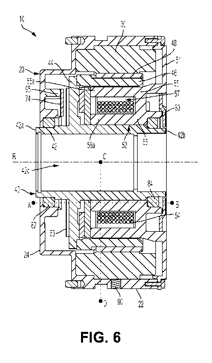
[0033] Referring now to Figures 1-6, an electric motor 10 is provided having a
housing 20, a stator 30, a rotor 40, a brake assembly 50, a bearing cover 60,
a feedback
system 70, a first bearing 82, and a second bearing 84. Housing 20 includes a
generally
cylindrical portion 22, a closed first end 24, and an open second end 26.
Cylindrical
portion 22 includes protruding ribs 22a and grooves 22b that allow for
securing housing 20
within a fixture during assembly of electric motor. Housing 20 also includes
strain relief
plugs 28.
[0034] Stator 30 is fixedly attached to the interior of cylindrical portion
22. Rotor 40
is positioned concentrically within stator 30 and separated therefrom by a
gap. Rotor 40
includes a hub portion 42, a disk portion 44, and a cylindrical portion 46.
Hub portion 42 has
a first end 42a, a second end 42b, and a through hole 42c therethrough.
Through hole 42c
may be utilized to support a shaft, such as an axle of a robot. Cylindrical
portion 46 can be
made of a magnetic material and includes a plurality of magnets 48 mounted
circumferentially thereabout. Disk portion 44 extends radially between hub
portion 42 and
4
CA 03134176 2021-09-17
WO 2020/214884 PCT/US2020/028629
cylindrical portion 46. Hub portion 42 and disk portion 44 may be made of a
non-magnetic
material.
[0035] Brake assembly 50 is fixedly attached to open second end 26 of housing
20
and includes a base 51, a brake housing 52, a brake plate 53, and an
electromagnetic brake
release 54. Base 51 combines with housing 20 to house electric motor 10. Brake
housing 52
is concentrically positioned within cylindrical portion 46 of rotor 40 and
separated therefrom
by a gap. Brake housing 52 includes a first cylindrical portion 55 and a
second cylindrical
portion 56. First cylindrical portion 55 extends axially from base 51 to an
axial end 55a.
Second cylindrical portion 56 extends axially from base 51 to an axial end
56a. Second
cylindrical portion 56 is positioned concentrically within first cylindrical
portion 55 and
separated therefrom by a slot 57. Base 51 and brake housing 52 are shown as a
combined
part. In other examples, base 51 and brake housing 52 could be separate parts
that can be
fixedly attached to each other.
[0036] Bearing cover 60 is attached to base 51 of brake assembly 50 by way of
fasteners 62. Use of bearing cover 60 allows second bearing 84 to be installed
from the
outside of electric motor 10.
[0037] Feedback system 70 includes a target 72 and a reader head 74. In one
example, target 72 can be an encoder disc that is attached to rotor 40. The
encoder disc can
have a pattern that can be read by reader head 74 and used to determine an
angular position of
target 72 and, therefore, an angular position of a shaft to which rotor 40 is
coupled.
[0038] As shown in Figures 7-9, stator 30 can include a lamination stack 31
with
slots 32 that are designed to retain stator wires 33. Stator wires 33 can be
can be energized
by a motor controller. Lamination stack 31 can include a stack of steel
plates. The steel
plates can be coated with an insulator that is used to prevent the voltage
applied to stator
wires 33 from shorting to the stack of laminated steel plates.
[0039] Further, stator 30 includes notches 34 that can be used for aligning
stator 30
with housing 20. For instance, a set screw 90 can be positioned through
cylindrical
portion 22 of housing 20 and engage one of the notches 34.
[0040] As shown in Figure 10, target 72 of feedback system 70 can be mounted
to
disk portion 44 of rotor by a plurality of fasteners 76. Further, as shown in
Figure 11,
Plurality of fasteners 76 can be arranged in an asymmetric pattern such that
target 72 can be
installed in only one orientation relative to plurality of magnets 48 of
rotor. This feature can
CA 03134176 2021-09-17
WO 2020/214884 PCT/US2020/028629
ensure proper commutation of electric motor 10 by a motor controller (not
shown) and can be
utilized in aligning a through shaft keyway 47 of rotor 40 with absolute
position information
provided on target 72.
[0041] As further shown in Figure 11, cylindrical portion 46 of rotor 40
includes
mounting holes 45 that can be aligned with north pole magnets of cylindrical
portion 46.
This feature can assure that disk portion 44 of rotor 40 turns in a correct
direction when
energized by the motor controller.
[0042] In some examples, part of the surface of disk portion 44 of rotor 40
that is
configured to be engaged by a brake lining of brake assembly 50 can include a
surface finish
that enhances the static coefficient of friction of the part of the surface.
This can allow
electric motor 10 to withstand more force without rotor 40 moving as well as
maximize the
stopping ability of brake assembly 50.
[0043] By way of example, Figure 12 illustrates that part of the surface of
disk
portion 44 includes a surface finish 49. Surface finish 49 is shown as a
knurled pattern that is
cut into the surface of disk portion 44. The knurled pattern includes
overlapping curved lines
that are cut into the surface of disk portion 44. In an example
implementation, the curved
lines can have a depth of a few thousandths of an inch, such as between one
thousandth and
five thousandths of an inch. Further, each curved line can be an arc of a
circle, such as an arc
of a circle having a radius of between one and two inches. The edges of
knurled pattern may
have a slightly higher gripping force if used with a brake pad material with
some compliance.
Advantageously, the knurled pattern shown in Figure 12 is easy to make (e.g.,
using an end
mill) and provides extra friction for braking. Surface finish 49 can take
other forms as well.
[0044] As shown in Figure 6, and more clearly in Figures 13 and 14, brake
plate 53 is
positioned on and covers at least a portion of axial ends 55a, 56a of first
cylindrical
portion 55 and second cylindrical portion 56. Brake plate 53 includes a brake
lining portion
58 which is biased against disk portion 44 of rotor 40 by springs 59 to
prevent rotation of
rotor 40 in a first operating condition. Springs 59 may be housed in recesses
55b in first
cylindrical portion 55 and/or recesses 56b in second cylindrical portion 56.
Recesses 55b and
recesses 56b are shown in Figure 15.
[0045] Further, electromagnetic brake release 54, shown in Figures 6, 13, and
14 as
an electromagnetic coil, can retract brake plate 53 such that a gap exists
between brake lining
portion 58 and disk portion 44 of rotor 40, thereby allowing rotation of rotor
40 in a second
6
CA 03134176 2021-09-17
WO 2020/214884 PCT/US2020/028629
operating condition. For instance, a motor controller may send a current to
electromagnetic
brake release 54, which causes brake plate 53 to retract. Pins 91 may be
utilized with brake
plate 43 and recesses 56b in second cylindrical portion 56 to prevent rotation
of brake plate
53 with respect to brake housing 52. Recesses 56b are shown in Figure 15.
[0046] As further shown in Figure 14, in some examples, axial end 55a of first
cylindrical portion 55 is axially offset from axial end 56a of second
cylindrical portion 56
such that the axial ends 55a, 56a are parallel but not in plane with one
another. With this
configuration, brake plate 53 only rests flat upon one of axial ends 55a, 56a.
As shown in
Figure 14, brake plate 53 only rests upon axial end 56a, which aides in
stability. In other
examples, brake plate 53 may only rest upon axial end 56a.
[0047] The out of plane axial ends 55a, 56a permit brake plate 53 to release
at an
adjustable current level. The current required to hold brake plate 53 in a
brake disengaged
position is directly proportional to the offset. When the two planes of axial
ends 55a, 56a are
separated by a larger distance, the current required to hold brake plate 53 in
a brake
disengaged position will be higher as compared to the current required to hold
brake plate 53
in the brake disengaged position when the two planes are separated by a
smaller distance.
This is because the air gap between brake plate 53 and a lower one of axial
ends 55a, 56a
creates reluctance to flow of magnetic flux. If the offset between axial ends
55a, 56a is too
small, the hysteresis in brake housing 52 may cause the retention of magnetic
flux and hence
hold brake plate 53 in the brake disengaged position even when the current
applied to
electromagnetic brake release is reduced to zero.
[0048] Referring again to Figure 6, rotation of rotor 40 within housing 20 is
enabled
by first bearing 82 and second bearing 84. First bearing 82 is mounted between
first end 42a
of hub portion 42 of rotor 40 and disk portion 44 of rotor 40. Second bearing
84 is mounted
between second end 42b of hub portion 42 of rotor 40 and disk portion 44 of
rotor 40. An
inner diameter of first bearing 82 and an inner diameter of second bearing 84
are larger than
an inner diameter of through hole 42c of rotor 40. Further, an outer diameter
of first
bearing 82 and an outer diameter of second bearing 84 are larger than an inner
diameter of
second cylindrical portion 56 of brake housing 52. Still further, the inner
diameter of first
bearing 82 and the inner diameter of second bearing 84 are less than the inner
diameter of
second cylindrical portion 56 of brake housing 52. Base 51 of brake assembly
50 is
configured such that second bearing 84 can be installed from the outside of
electric motor 10.
After second bearing is installed, bearing cover 60 can be attached to base
51, allowing the
7
CA 03134176 2021-09-17
WO 2020/214884 PCT/US2020/028629
sizes of brake housing 52 and electromagnetic brake release 54 to be
maximized. Otherwise,
the inner diameter of second cylindrical portion 56 would need to increase to
permit second
bearing 84 to pass through during assembly, thereby reducing the size of brake
housing 52.
Advantageously, increasing the sizes of brake housing 52 and electromagnetic
brake
release 54 maximizes the magnetic field that is used to retract brake plate
53. This
maximized magnetic field, in turn, permits the use of stronger springs 59,
which increases the
stopping and holding force of brake assembly 50.
[0049] As further shown in Figure 6, when assembled, electric motor 10 is
configured
such that a line segment AB that is parallel to an axis of rotation R of rotor
40 passes through
disk portion 44 of rotor 40, brake assembly 50, first bearing 82, and brake
plate 53. In some
examples, line segment AB can also pass through a spring 59 housed within a
recess 56b of
second cylinder portion 56 (not shown in Figure 6). In addition, when
assembled, electric
motor 10 is configured such that a line segment CD that is perpendicular to
the axis of
rotation R of rotor 40 passes through through hole 42c, brake housing 52,
electromagnetic
brake release 54, cylindrical portion 46, and stator 30.
[0050] In some examples, disk portion 44 of rotor 40 is non-magnetic or mildly
magnetic. Making disk portion 44 out of a non-magnetic material can eliminate
the coupling
between brake assembly 50 and feedback system 70 and can also minimize the
current
required to retract brake plate 53. This may be counterintuitive to a motor
designer as a
magnetic material will typically create a shielding effect. However, in
electric motor 10,
leakage flux that travels within through hole 42c of hub portion 42 is
attracted to a magnet
disk that is part of target 72 on the opposite side of disk portion 44 from
brake assembly 50.
The extra magnetic field from electromagnetic brake release 54 can interfere
with feedback
system 70 especially if feedback system 70 works by detecting magnetic field
from target 72.
[0051] In some examples, it may be desirable for both wires that energize the
electric
motor and the wires that control electromagnetic brake release 54 to exit
electric motor 10 at
the same end of housing 20. For instance, it may be desirable for both of
these wires to exit
electric motor 10 by way of closed first end 24 of housing 20. This can create
a design
challenge for the wires that control electromagnetic brake release 54, since
electromagnetic
brake release 54 is on the side of electric motor 10 that is opposite to
closed first end 24. It
may be desirable to route the wires inside of electric motor 10, to help
protect the wires from
an outside environment. There may be limited room for such wires to travel
through electric
motor 10 within the gap between stator 30 and rotor 40. However, slight
movement of the
8
CA 03134176 2021-09-17
WO 2020/214884 PCT/US2020/028629
wires within that gap could cause the wires to rub rotor 40, leading to
failure of brake
assembly 50.
[0052] Accordingly, as shown in Figures 15 and 16, to route the wires that
control
electromagnetic brake release 54 through electric motor 10 and to closed first
end 24 of
housing 20, brake assembly 50 includes a brake wire passageway 92 connecting
slot 57 with
an inner side of base 51. Brake wire passageway 92 is provided at the
intersection of first
cylindrical portion 55 and base 51. Brake wire passageway 92 permits wires 93
attached to
electromagnetic brake release 54 to safely transverse the cavity of electric
motor that contains
rotating rotor 40, hence eliminating the failure mode in which wires 93 are
inadvertently
worn by the rotating rotor 40.
[0053] After passing from slot 57 to the inner side of base 51 by way of brake
wire
passageway 92, wires 93 can be routed to closed first end 24 of housing 20 in
various ways.
As one example, after exiting brake wire passageway 92, wires 93 can travel in
a groove 94
cut into the interior surface of cylindrical portion 22 of housing. Groove 94
is shown in
Figures 17 and 18. With this approach, wires 93 can travel between stator 30
and housing 20.
As another example, after exiting brake wire passageway 92, wires 93 can
travel through
stator 30. For instance, wires 93 can travel through a slot 35 of stator 30
that contains stator
wires 33. Slot 35 is shown in Figure 9.
[0054] As noted above, electric motor 10 can include a set screw 90 that is
positioned
through cylindrical portion 22 of housing 20 and used to engage a notch 34 of
stator 30. This
permits stator 30 to be aligned with housing 20 in only one orientation. In
some examples, as
shown in Figure 18, an inner side of closed first end 24 of housing 20 can
include a mounting
pad 95 used to mount reader head 74 of feedback system 70 to housing 20. This
results in
reader head 74 also being aligned with housing 20 in only one orientation.
Because both
stator 30 and reader head 74 are mounted to housing 20 in only one
orientation, a motor
controller can properly energize stator 30 without carrying out an electronic
alignment
procedure. In addition, feedback system 70 can operate without having to carry
out an
alignment procedure. The use of notch 34 and the mounting pad 95 can therefore
reduce
production costs and increase reliability.
[0055] Figure 19 shows electric motor 10 coupled to an axle 100 of a robot
102. Axle
100 runs through the center of electric motor 10 and is attached to a tire
104. At least one
surface of electric motor 10 is attached to a body 106 of robot 102. For
instance, part of
9
CA 03134176 2021-09-17
WO 2020/214884 PCT/US2020/028629
housing 20 of electric motor is attached to body 106 of robot 102. In
operation, electric
motor 10 can rotate axle 100 in one or more directions, hold axle 100 in
place, and/or cause
axle 100 to stop rotating, thereby controlling movement of robot 102.
[0056] The description of the different advantageous arrangements has been
presented for purposes of illustration and description, and is not intended to
be exhaustive or
limited to the examples in the form disclosed. After reviewing and
understanding the
foregoing disclosure, many modifications and variations will be apparent to
those of ordinary
skill in the art. Further, different examples may provide different advantages
as compared to
other examples. The example or examples selected are chosen and described in
order to best
explain the principles, the practical application, and to enable others of
ordinary skill in the
art to understand the disclosure for various examples with various
modifications as are suited
to the particular use contemplated.