Note: Descriptions are shown in the official language in which they were submitted.
CA 03134434 2021-09-20
WO 2020/197788 PCT/US2020/022423
- 1 -
SUPPORT GARMENT TESTING SYSTEM
FIFLD OF THE INVENTION
Aspects herein relate to a testing system for measuring the level of support
provided by a support garment, such as a bra.
BACKGROUND OF THE INVENTION
Historically it has been difficult to assign a level of support provided by a
support garment to a wearer's breasts in a reproducible and measurable way.
Instead, it has
often been a subjective determination based on a fit model's perception of the
level of
support.
BRIEF DESCRIPTION OF THE DRAWING
Examples of aspects herein are described in detail below with reference to the
attached drawing figures, wherein:
FIG. 1 illustrates a front view of an example torso form for use in a support
garment testing system in accordance with aspects herein;
FIG. 2 illustrates a back view of the torso form of FIG. 1 in accordance with
aspects herein;
FIG. 3 illustrates a side view of the torso form of FIG. 1 in accordance with
aspects herein;
FIG. 4 illustrates a bottom view of the torso form of FIG. 1 in accordance
with
aspects herein;
FIG. 5A illustrates a cross-sectional view of a first example torso form in
accordance with aspects herein;
FIG. 5B illustrates a front view of an optional transition insert for the
first
example torso form of FIG. 5A in accordance with aspects herein;
FIG. 5C illustrates a cross-sectional view taken along cut line 5C-5C of FIG.
5B in accordance with aspects herein;
FIG. 5D illustrates a cross-sectional view of a second example torso form in
accordance with aspects herein;
CA 03134434 2021-09-20
WO 2020/197788 PCT/US2020/022423
- 2 -
FIG. 5E illustrates a first insert for use in the second example torso form of
FIG. 5D in accordance with aspects herein;
FIG. 5F illustrates a second insert for use in the second example torso form
of
FIG. 5D in accordance with aspects herein;
FIG. 6A illustrates a front perspective view of a core for use in the example
torso form of FIG. 5D in accordance with aspects herein;
FIG. 6B illustrates a back perspective view of the core of FIG. 6A in
accordance with aspects herein;
FIG. 7 illustrates a view of a front mold for use in forming example torso
forms in accordance with aspects herein;
FIG. 8 illustrates a view of a back mold for use in forming the example torso
forms in accordance with aspects herein;
FIG. 9 illustrates an example process for forming a front portion of an
example torso form using the front mold of FIG. 7 in accordance with aspects
herein;
FIG. 10 illustrates an example process for forming the example torso form that
utilizes the front mold of FIG. 7 and the back mold of FIG. 8 in accordance
with aspects
herein;
FIG. 11 illustrates an example support garment testing system in accordance
with aspects herein;
FIG. 12 illustrates a flow diagram of an example method of testing a level of
support provided by a support garment in accordance with aspects herein;
FIG. 13 illustrates an example method of manufacturing a torso form for use
in a support garment testing system in accordance with aspects herein; and
FIG. 14 illustrates a block diagram of an example computing environment
suitable for use in implementing aspects described herein.
DETAILED DESCRIPTION OF THE INVENTION
The subject matter of the present invention is described with specificity
herein
to meet statutory requirements. However, the description itself is not
intended to limit the
scope of this disclosure. Rather, the inventors have contemplated that the
claimed or
disclosed subject matter might also be embodied in other ways, to include
different steps or
combinations of steps similar to the ones described in this document, in
conjunction with
CA 03134434 2021-09-20
WO 2020/197788 PCT/US2020/022423
- 3 -
other present or future technologies. Moreover, although the terms "step"
and/or "block"
might be used herein to connote different elements of methods employed, the
terms should
not be interpreted as implying any particular order among or between various
steps herein
disclosed unless and except when the order of individual steps is explicitly
stated.
Historically it has been difficult to assign a level of support provided by a
support garment to a wearer's breasts in a reproducible and measurable way.
Instead, it has
often been a subjective determination based on a fit model's perception of the
level of
support. Aspects herein are directed to a support garment testing system that
may be used to
assess the level of support provided by a support garment to a female wearer's
breasts. The
testing system is able to assess the level of support provided by multiple
different support
garments in a reproducible and measurable way with the result that a consumer
can
confidently select a support garment with the appropriate level of support for
her needs.
In one aspect, the support garment testing system utilizes at least a torso
form
having a first breast structure and a second breast structure, a sensor such
as a motion
tracking sensor associated with the torso form, a motion platform that can
move through up to
six degrees of motion, and a computing system usable for analyzing the data
captured by the
sensor. In example aspects, the sensor is integrated into the torso form
although it is
contemplated herein that the sensor may be affixed or secured to an outer
surface of the torso
form. More specifically, the sensor is positioned within one or more of the
first breast
structure and the second breast structure including placement within the
nipple area of the
respective breast structure. By positioning the sensor within one or more of
the first breast
structure and the second breast structure, wear and tear on the sensor is
reduced and
inadvertent displacement or movement of the sensor is also reduced. In one
aspect, a single
sensor may be used such that the single sensor is positioned within one of the
first breast
structure or the second breast structure. In another aspect, two sensors may
be used for
redundancy with one sensor being positioned within the first breast structure
and the second
sensor being positioned within the second breast structure. When two sensors
are used, only
one sensor may be active at a time to increase the longevity of the torso
form. In line with
this, it is contemplated herein that the torso form may be configured so that
the sensor may be
replaced when needed.
A support garment, such as a bra, is secured on to the torso form, and the
torso
form is removably mounted to the motion platform. The motion platform is then
actuated to
move in one or more directions. The amount of displacement (both linear and
rotational),
CA 03134434 2021-09-20
WO 2020/197788 PCT/US2020/022423
- 4 -
velocity of displacement, and/or frequency of displacement of the first breast
structure and/or
the second breast structure is captured by way of the sensor while the motion
platform is
moving. Additional data related to breast displacement and/or movement may
also be
captured by positioning one or more external markers on the torso form and
capturing
.. movement of the markers using a motion capture system. Moreover, additional
sensors, such
as load sensors and/or stretch sensors may also be utilized.
The displacement data provided by the sensor, and optionally the data
captured through the motion capture system, is used to an assign a level of
support to the
support garment. In one example, the level of support is determined by
comparing the
displacement data captured while the support garment is secured to the torso
form with
displacement date captured when a support garment is not secured to the torso
form (i.e.,
when the torso form is in a "braless" state) where similar testing conditions
are used in both
(e.g., same movements in specified directions, same degrees of the movement in
the specified
directions, same frequencies of the movements in the specified directions,
same duration of
testing cycle, and the like). By utilizing the system described herein, a
measurable and
reproducible way of assigning levels of support to support garments is
achieved.
It is contemplated herein that the torso form is configured such that it is
possible to change the size of the first and second breast structures by the
addition or removal
of materials to or from the first and second breast structures. This feature
expands the use of
the torso form to determine the level of support provided by a support garment
configured for
wear by wearers with small breasts, medium breasts, and large breasts.
With respect to the torso form, materials used to create the torso form are
selected to replicate as much as possible the breast displacement that
naturally occurs when a
human wearer engages in, for instance, athletic activities. As explained more
fully below, it
was determined that a multi-layered torso form, as opposed to just having
breast structures
positioned on a rigid frame, helps to facilitate the displacement
characteristics that occur
naturally with the human breast. In other words, materials used to create the
torso form may
be selected to mimic, as much as possible, physical properties associated with
human breasts,
human skin, human muscle, and/or human skeletal structures. The materials
include skin
surrogate materials, breast surrogate materials, muscle surrogate materials,
and/or skeletal
surrogate materials. In example aspects, the skeletal surrogate materials may
comprise a
rigid core such as a rigid foam core to provide structural stability to the
torso form and to
enable the torso form to be mounted to, for instance, the motion platform.
88978603
- 5 -
The sensor, in example aspects, may comprise a motion tracking sensor that is
able to
capture degrees of displacement, both linear and rotational, frequency of
movement, and/or
velocity of movement through up to six degrees of movement. By associating the
sensor with the
breast structure and specifically with the nipple area of the breast
structure, the sensor is able to
accurately capture the displacement experienced by the breast structure during
movement.
Moreover, since the nipple area typically represents the anterior-most aspect
of a breast,
positioning the sensor in this location enables the sensor to capture the
maximum amount of
displacement experienced by the breast structures.
According to an aspect, there is provided a support garment testing system
comprising: a
torso Timm having a first breast structure and a second breast structure; a
motion platform, the
torso form secured to the motion platform; and a sensor positioned within one
or more of the first
breast structure and the second breast structure, wherein the sensor is a
motion tracking sensor.
According to another aspect, there is provided a support garment testing
system
comprising: a torso form having a first breast structure and a second breast
structure, the first
breast structure and the second breast structure comprising a breast surrogate
material and a skin
layer, wherein one or more of the first breast structure and the second breast
structure include a
sensor; and a motion platform secured to the torso form, wherein: the torso
form secured to the
motion platform comprises a superior/inferior z-axis, a medial/lateral y-axis,
and an
anterior/posterior x-axis; and the motion platform, when actuated,
rotationally moves the torso
form relative to one or more of the superior/inferior z-axis and the
anterior/posterior x-axis,
wherein the sensor comprises a motion tracking sensor.
According to another aspect, there is provided a method for testing a level of
support
provided by a support garment, the method comprising: in a test cycle:
securing the support
garment to a torso form having a first breast structure and a second breast
structure, the torso
form secured to a motion platform, the torso form having an integrated sensor,
wherein the
integrated sensor comprises a motion tracking sensor; actuating the motion
platform to cause the
torso form to move in one or more degrees of movement; and measuring a first
amount of
displacement of one or more of the first breast structure and the second
breast structure using the
integrated sensor while the motion platform is actuated.
Positional terms as used herein such as "front," "back," "top," "bottom,"
"superior,"
"inferior," and the like are with respect to a torso form in an upright
position (e.g., a neck area of
the torso form positioned above a waist area of the torso form) and with the
breast structures
Date recue/Date received 2023-04-19
88978603
- 5a -
positioned on the front of the torso form. These same terms when used to
describe, for example,
a support garment contemplate that a front portion of a support garment is
configured to cover
the front of the torso form, and a back portion of the support garment is
configured to cover the
back of the torso foim.
Terms such as "releasably secured," means that the torso portion can be
mounted to a
motion platform when testing is desired and can be removed from the motion
platform when
needed. Releasable attachment technologies may comprise screws, adhesives,
clamps, and the
like. When referring to "breast structures" and a "nipple area," reference is
made to typical
female physiology where breasts are located generally symmetrically on the
upper front torso of
a wearer and the nipple area of the breast is typically located at an apex of
the breast. The tenn
"about" as used herein means within 5% of a designated value.
As described herein, the sensor may be "associated" with the torso foini or
with the breast
structures and/or nipple area of the breast structures. The term "associated"
means that the sensor
is integrated into the torso form as the torso form is casted, the sensor is
positioned within an
interior of the torso form by way of a conduit tube positioned within the
torso form (the
placement of the sensor may occur in a post-casting step), the sensor is
secured or affixed to an
outer-surface of the torso form, and the like. Any and all aspects, and any
variation thereof, are
contemplated as being within aspects herein.
Material properties of the different components of the torso form are provided
herein and
include storage modulus, hardness, tensile modulus, and elongation at break.
Storage modulus is
used with viscoelastic materials and measures both the stored energy,
represented by the elastic
portion of the material, and the energy dissipated as heat,
Date recue/Date received 2023-04-19
CA 03134434 2021-09-20
WO 2020/197788 PCT/US2020/022423
- 6 -
represented by the viscous portion. Storage modulus as used herein is measured
by dynamic
material analysis (DMA) at 1Hz at room temperature. The hardness of materials
described
herein may be determined by measuring the resistance of a sample to material
deformation
due to a constant compression load from an object. As used herein, hardness is
measured
using ASTM D-2240. Tensile modulus is a measure of the resistance to elastic
deformation
that a material has and is commonly measured by dividing the amount of stress
applied to a
material by the strain the material undergoes. A testing standard used to
measure tensile
modulus is ASTM D-412. Elongation at break relates to the ability of a
material to resist
changes of shape without cracking or breaking and is the ratio between final
length and initial
length after breakage of a material at a controlled temperature. A testing
standard used to
measure elongation at break is ASTM D-412.
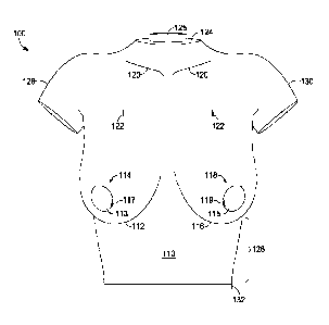
FIGs. 1 and 2 illustrate front and back views of a first example torso form
100.
The torso form 100 includes a front torso area 110 having a first breast
structure 112 with a
first nipple area 114 and a second breast structure 116 with a second nipple
area 118. The
front torso area 110 may further include anatomical features such as clavicles
120. With
respect to FIG. 2, the torso form 100 further includes a back torso area 210
that may include
anatomical features such as scapula 212. The anatomical features such as the
clavicles 120,
the scapula 212, and the first and second breast structures 112 and 116 with
the first and
second nipple areas 114 and 118 may provide landmarks for properly positioning
a support
garment on the torso form 100. To aid in this, and in one example, the first
and second nipple
areas 114 and 118 may be formed to protrude from the first and second breast
structures 112
and 116 and/or to have a different density (e.g., more firm) to provide a
visual and/or a tactile
landmark. In another example, the first and second nipple areas 114 and 118
may optionally
each include a sensor receptacle 113 and 115 respectively. Alternatively, the
torso form 100
.. may include a single sensor receptacle such as the sensor receptacle 113 or
the sensor
receptacle 115. The sensor receptacles 113 and 115 may be formed of a material
having a
different density and/or texture to also provide a visual and/or a tactile
landmark. Any and all
aspects, and any variation thereof, are contemplated as being within aspects
herein.
The optional sensor receptacles 113 and 115 may, in example aspects, be
openable by way of, for instance, opening mechanisms 117 and 119 (e.g., a
hinged opening)
respectively to allow access to a space positioned behind the first and second
nipple areas 114
and 118 as further explained with respect to FIG. 5A. The sensor described
herein may be
positioned within the space and thereby may be accessed by way of the opening
mechanisms
CA 03134434 2021-09-20
WO 2020/197788 PCT/US2020/022423
-7-
117 and 119 of the sensor receptacles 113 and 115. In another example, the
first and second
nipple areas 114 and 118 may not include the sensor receptacles 113 and 115.
In this aspect,
the sensor described herein may be positioned within the breast surrogate
material of the first
and second breast structures 112 and 116 and secured to, for example, the
first and second
nipple areas 114 and 118 as shown in FIG. 5D.
In example aspects, the torso form 100 may further include optional
registration marks, such as registration marks 122 located on one or more of
the front torso
area 110 and/or the back torso area 210, to further guide placement of the
support garment on
the torso form 100. The registration marks 122 may include visual indicia that
are applied to
.. a skin surface of the torso form 100 during or after the torso form 100 is
casted, or the
registration marks 122 may be integrated into the skin surface of the torso
form 100 when the
torso form 100 is casted or in a post-casting step. The location of the
registration marks 122
is illustrative only and the registration marks 122 may be located in other
positions in
accordance with aspects herein.
The torso form 100 further includes a neck portion 124 through which, in
example aspects, part of a core 125 may extend, a waist portion 126 extending
below the first
and second breast structures 112 and 116, a first arm portion 128, and a
second arm portion
130. The first and second arm portions 128 and 130 may comprise just the upper
part of an
arm structure to keep the weight of the torso form 100 down, to make it easier
to transport,
and to make it easier to position a support garment on the torso form 100. In
example
aspects, a mounting structure 132 is secured to a bottom surface of the torso
form 100 where
the mounting structure 132 is useable for mounting the torso form 100 to a
motion platform.
The back torso area 210 may optionally comprise one or more ports 214 and
216. The ports 214 and 216 may be useable for placing or replacing sensors in
the first and
second breast structures 112 and 116. As well, the ports 214 and 216 may be
useable to add
additional breast surrogate material to the first and second breast structures
112 and 116 to,
for instance, increase the size of the first and second breast structures 112
and 116 and/or to
decrease the skin layer thickness of the first and second breast structures
112 and 116. The
ports 214 and 216 may also be used to remove breast surrogate material from
the first and
second breast structures 112 and 116 to decrease the size of the first and
second breast
structures 112 and 116. Any and all aspects, and any variation thereof, are
contemplated as
being within aspects herein.
CA 03134434 2021-09-20
WO 2020/197788 PCT/US2020/022423
- 8 -
FIGs. 3 and 4 illustrate a side view and a bottom view of the torso form 100
respectively. The side view of FIG. 3 depicts the first breast structure 112
with the first
nipple area 114. It is known that larger-breasted women often need more
support than
smaller-breasted women. To better meet this need, the torso form 100 may be
created to have
the first and second breast structures 112 and 116 simulate a 36D through a
36DD cup size,
although it is contemplated herein that the torso form 100 may be created to
have breast
structures in different sizes including smaller and larger sizes than 36D or
36DD such as, for
example, 32A-DD, 34A-DD, 38A-DD, sizes larger than DD and the like. In example
aspects,
the first and second breast structures 112 and 116 may be adapted to assume a
number of
different sizes through the addition and removal of breast surrogate material
to the first and
second breast structures 112 and 116. It is further contemplated herein that a
circumference
of the torso form 100 in the area where the lower part of the first and second
breast structures
112 and 116 meet the chest may be from about 33 inches to about 35 inches, or
from about
33.5 inches to about 34.5 inches.
The bottom view of FIG. 4 illustrates the mounting structure 132. As
mentioned, the mounting structure 132 is used to releasably secure the torso
form 100 to a
motion platform. Reference numeral 410 which indicates screw holes,
illustrates an example
way of securing the torso form 100 to a motion platform although other
attachment means are
contemplated. In example aspects, the mounting structure 132 may comprise a
metal plate to
provide structural stability when the torso form 100 is mounted on a motion
platform.
FIG. 5A depicts an example cross-sectional view of the torso form 100 taken
through the first breast structure 112 and illustrates one example structure
of the torso form
100. As mentioned above, the materials used to create the torso form 100 are
selected to
simulate, as much as possible, a human female torso in order to accurately
reproduce the
displacement of breasts that occurs when a human wearer engages in physical
activity. In
example aspects, the torso form 100 comprises a skin layer 510 shown with
positively sloped
hatching, a breast surrogate material 512 indicated with stippling, a muscle
layer 514 shown
with negatively sloped hatching, and the core 125 shown with no shading. The
skin layer 510
forms, at least in part, an outer surface of the torso form 100. Although
shown as extending
along an entire perimeter of the outer surface of the torso form 100 in FIG.
5A, it is
contemplated that there may be portions of the torso form 100 from which the
skin layer 510
is absent. For instance, the bottom of the torso form 100 may not comprise the
skin layer
510. As well, the skin layer 510 may be absent around the neck portion 124 or
may be absent
CA 03134434 2021-09-20
WO 2020/197788 PCT/US2020/022423
- 9 -
from the terminal ends of the first and second arm portions 128 and 130. Any
and all aspects,
and any variation thereof, are contemplated as being within the scope herein.
The first and second breast structures 112 and 116 comprise the skin layer 510
and the breast surrogate material 512. For instance, the skin layer 510 may
define a cavity
for each of the first and second breast structures 112 and 116, such as cavity
513, in which
the breast surrogate material 512 is positioned. The muscle layer 514 forms,
in part, an
interior of the torso form 100, and the core 125 also forms, in part, the
interior of the torso
form 100. Thus, as shown in FIG. 5A, the torso form 100 includes the core 125
which is at
least partially surrounded or enclosed within the muscle layer 514. In turn,
the muscle layer
514 is at least partially surrounded or enclosed within the skin layer 510.
The skin layer 510
also at least partially surrounds or encloses the breast surrogate material
512.
Starting first with the skin layer 510, in example aspects, the skin layer 510
is
formed from a silicone material, which is liquid in an uncured state. An
example silicone
material may include, for example, Dragon-SkinTM 10 VERY FAST produced by
Smooth-
On , Inc. located in Macungie, Pennsylvania. The skin layer 510 may be tinted
with
pigment to achieve a desired skin tone. In example aspects, the material used
to form the
skin layer 510 is selected to have a storage modulus (G') from about 0.35 MPa
to about 0.95
MPa, from about 0.45 MPa to about 0.85 MPa, from about 0.55 MPa to about 0.75
MPa, or
about 0.65 MPa. The skin layer 510 is also selected to have a Shore A hardness
from about 7
to about 13, from about 8 to about 12, from about 9 to about 11, or about 10.
The skin layer
510 is additionally selected to have a tensile modulus from about 75% to about
100%, from
about 85% to about 100%, from about 95% to about 100%, or about 100% of
0.152MPa.
The skin layer 510 is further selected to have an elongation at break from
about 955% to
about 1040%, from about 970% to about 1030%, from about 980% to about 1020%,
from
about 990% to about 1010%, or about 1000%.
In example aspects, the thickness of the skin layer 510 may be variable
depending on the location on the torso form 100. For example, the thickness
may range from
about 0.8 mm to about 7 mm, from about 0.9 mm to about 6.5 mm, from about 1.0
mm to
about 6.0 mm, from about 1.25 mm to about 5.75 mm, or from about 1.5 mm to
about 5 mm.
More specifically, areas of the torso form 100 for which the skin layer 510
may need greater
elongation would generally have a thinner skin layer 510 while areas of the
torso form for
which the skin layer 510 may need less elongation would generally have a
thicker skin layer
510. To use an example, because the first and second breast structures 112 and
116 may
CA 03134434 2021-09-20
WO 2020/197788 PCT/US2020/022423
- 10 -
experience more displacement during movement compared to, for instance, the
back torso
area 210, the first and second arm portions 128 and 130 or the waist portion
126, the
thickness of the skin layer 510 of the first and second breast structures 112
and 116 may be
less than the thickness of the skin layer 510 at the back torso area 210, the
first and second
arm portions 128 and 130, and/or the waist portion 126. Having a thinner skin
layer 510 for
the first and second breast structures 112 and 116 means that the skin layer
510 can undergo a
greater degree of elongation during displacement. In example aspects, the
thickness of the
skin layer 510 for the first and second breast structures 112 and 116 may
comprise from
about 0.8 to about 1.8 mm, from about 0.9 mm to about 1.7 mm, from about 1.0
mm to about
1.65 mm, from about 1.25 mm to about 1.6 mm, or about 1.5 mm, and the
thickness of the
skin layer 510 for the back torso area 210, the first and second arm portions
128 and 130, the
waist portion 126, and remaining portions of the torso form 100 not including
the first and
second breast structures 112 and 116 may comprise from about 3.0 mm to about
8.0 mm,
from about 3.5 mm to about 7.0 mm, from about 4.0 mm to about 6.00 mm, or
about 5.0 mm.
The breast surrogate material 512 is positioned within the first and second
breast structures 112 and 116. In example aspects, a skin layer 511 may be
positioned
interior (i.e., closer to the center of the torso form 100) to the breast
surrogate material 512 so
that it acts to contain the breast surrogate material 512 within the first and
second breast
structures 112 and 116 and effectively seals the cavity 513. In example
aspects, the breast
surrogate material 512 may comprise a combination of polyethylene glycol
(PEG), alumina
powder, and tungsten powder. In example aspects the PEG may comprise PEG-400-1
produced by ChemWorld with locations in Kennesaw, Georgia, Salt Lake City,
Utah, and
Taylor, Michigan, the alumina powder may comprise ALUMP005-5 from SMS Labs
with
headquarters in Sturbridge, Massachusetts, and the tungsten powder may
comprise 510106
tungsten powder from Millipore Sigma with headquarters in Damstadt, Germany.
The PEG,
alumina powder and tungsten powder may be mixed in various combinations at
example
ratios of from about 2.5 liters PEG, 400 grams alumina powder, and 2800 grams
tungsten
powder to about 1.5 liters PEF, 200 grams alumina powder, and 2600 grams
tungsten
powder, or about 2 liters PEG, 300 grams alumina powder, and 2700 grams
tungsten powder
(approximately 6 pounds of tungsten powder) to achieve a desired specific
gravity and
viscosity. In example aspects, the tungsten powder is used to add a desired
mass to the breast
surrogate material 512, and the alumina powder is used to add a desired
viscosity to the
breast surrogate material 512. In example aspects the breast surrogate
material has a specific
CA 03134434 2021-09-20
WO 2020/197788 PCT/US2020/022423
- 11 -
gravity of from about 1.5 to about 3.5, from about 1.75 to about 3.0, from
about 2.0 to about
2.75, or about 2.4. It has been found that configuring the breast surrogate
material 512 as
described above simulates natural breast movement/displacement during
exercise. Further,
aspects herein contemplate adjusting the amount of tungsten powder and the
amount of
alumina powder to achieve a desired specific gravity and viscosity.
The muscle layer 514 forms, at least in part, the interior of the torso form
100
and helps to provide structural stability to the torso form 100. Materials
used to form the
muscle layer 514 are selected to mimic, as much as possible, characteristics
of human torso
muscles. For instance, materials used to form the muscle layer 514 may be
selected to have a
higher tensile modulus and a lower elongation at break compared to, for
instance, the
materials used to form the skin layer 510. The muscle layer 514 may be formed
from a
silicone material such as, for example, Dragon-SkinTM 30 produced by Smooth-On
Inc.
Pigments may be added to the silicone material to achieve a desired coloration
of the muscle
layer 514. In example aspects, the material used to form the muscle layer 514
is selected to
have a storage modulus (G') from about 0.12 MPa to about .20 MPa, from about
0.13 MPa to
about 0.19 MPa, from about 0.14 MPa to about 0.18 MPa, from about 0.15 MPa to
about 0.17
MPa, or about 0.16 MPa. The muscle layer 514 is further selected to have a
Shore A
hardness from about 27 to about 33, from about 28 to about 32, from about 29
to about 31, or
about 30. The muscle layer 514 is also selected to have a tensile modulus from
about 75% to
about 100%, from about 85% to about 100 %, from about 95% to about 100% or
about 100%
at 0.593 MPa. And the muscle layer 514 is selected to have an elongation at
break from
about 330% to about 400%, from about 340% to about 390%, from about 350% to
about
380%, from about 355% to about 370%, or about 360%. Moreover, materials used
to form
the muscle layer 514 are selected to be compatible with the materials used to
form the skin
layer 510 and to promote adhesion with the materials used to form the skin
layer 510 to
reduce the chances of delamination.
FIG. 5A further illustrates an optional transition insert 518 that helps to
provide a transition between the first breast structure 112 and the area of
the torso form 100
superior to or above the first breast structure 112. A similar transition
insert may also be used
for the second breast structure 116. The transition insert 518 may have
material properties
intermediate between the breast surrogate material 512 and the skin layer 510.
Providing a
gradual transition between the material properties associated with the first
and second breast
structures 112 and 116 and the area of the torso form 100 superior to the
first and second
CA 03134434 2021-09-20
WO 2020/197788 PCT/US2020/022423
- 12 -
breast structures 112 and 116 may reduce the stress on the skin layer 510 in
this area thereby
increasing the longevity of the torso form 100.
The transition insert 518 includes a crescent-shaped foam material formed
using, for instance, an open cell foam such as a polystyrene foam or a
polyurethane foam. A
front view of the transition insert 518 is shown in FIG. 5B, and FIG. 5C
illustrates a cross-
section of the transition insert 518 taken along cut line 5C-5C of FIG. 5B.
The crescent
shape of the transition insert 518 as shown in FIG. 5B enables the transition
insert 518 to
curve around the medial, upper, and lateral aspects of the first breast
structure 112. As shown
in FIG. 5C, the transition insert 518 has a back side 530, a front side 532, a
bottom 534, and a
top 536. The front side 532 of the transition insert 518 tapers as it extends
from bottom 534
to the top 536 of the transition insert 518 to ensure a gradual transition
between the first
breast structure 112 and the area of the torso form 100 superior to the first
breast structure
112.
As shown in FIG. 5A, the front side 532 of the transition insert 518 is in
contact with the skin layer 510, and the back side 530 of the transition
insert 518 is partially
in contact with the skin layer 511 and partially in contact with the muscle
layer 514. By
using an open cell foam to form the transition insert 518, the materials
forming the skin layer
510, the skin layer 511, and the muscle layer 514 may at least partially
impregnate the
transition insert 518 helping to secure the transition insert 518 and reduce
delamination
between the transition insert 518, the skin layer 510, the skin layer 511, and
the muscle layer
514. The core 125 forms, at least in part, the interior of the torso form 100
and will be
discussed below with respect to FIGs. 6A and 6B.
FIG. 5A further illustrates one example way of positioning a sensor 540
within, for instance, the first breast structure 112. In example aspects, a
conduit tube 542
.. may be co-molded with the torso form 100 such that it extends from the
first nipple area 114
of the first breast structure 112, through the breast surrogate material 512,
through the skin
layer 510, through the muscle layer 514, optionally through the core 125, and
the skin layer
510, to the back torso area 210 of the torso form 100. In this aspect, the
port 214 provides
access to the conduit tube 542. A similar configuration may be used for the
second breast
structure 116. In example aspects, the conduit tube 542 may include a flexible
tube formed
from, for example, latex or silicone. Although shown as extending relatively
straight, it is
contemplated herein that the flexible nature of the conduit tube 542 may allow
for some
flexing and curving as the conduit tube 542 extends from the port 214 to the
first nipple area
CA 03134434 2021-09-20
WO 2020/197788 PCT/US2020/022423
- 13 -
114. For example, the conduit tube 542 may be positioned to include one or
more loops to
allow a degree of mechanical stretch as the torso form 100 is manipulated.
As shown in the magnified view 544, the conduit tube 542 may terminate in
the sensor receptacle 113, where the sensor receptacle 113 may comprise a
bulbous form
although other forms are contemplated herein. The sensor receptacle 113 may
also be co-
molded with the torso form 100. The sensor receptacle 113, in one example
aspect, is an
integral extension of the conduit tube 542. Or, in another example aspect, the
sensor
receptacle 113 is a separate element from the conduit tube 542 and may be
secured to the
conduit tube 542 using, for instance, an adhesive or other types of bonding or
sealing
methods. When formed as a separate element, it is contemplated herein that the
sensor
receptacle 113 may be formed of a more rigid material such as, for example,
plastic, to allow
for easier manipulation of the sensor receptacle 113. As described above, the
sensor
receptacle 113 may comprise the opening mechanism 117 (shown in FIG. 1) to
allow access
to a space 541 within the sensor receptacle 113.
In example aspects, the torso form 100 may be casted so that the skin layer
510 at the first and second nipple areas 114 and 118 extends inwardly (i.e.,
toward the core
125) to form a depression 543 in which the sensor receptacle 113 is positioned
allowing easy
access to the sensor receptacle 113. The sensor receptacle 113 may, in example
aspects,
protrude slightly past the outer plane of the first breast structure 112 to
provide a visual
and/or tactile marker that may help in positioning a support garment on the
torso form 100.
The sensor 540 is positioned within the sensor receptacle 113 so that it is
effectively positioned at the first nipple area 114 of the first breast
structure 112. As
described above, placement of the sensor 540 within the first nipple area 114
allows for
measurement of the maximum displacement experienced by the first breast
structure 112
during movement. The sensor 540 includes a sensor lead 548 that extends from
the sensor
540 through the conduit tube 542 to exit the back torso area 210 by way of the
port 214
where it is connected to, for instance, a power supply and/or a processor
(indicated
generically by the term "processor" and indicated by the reference numeral
550). In example
aspects, the sensor 540 may be a motion tracking sensor that tracks movement
through six
degrees of motion. One example sensor that may be used herein is the Micro
Sensor 1.8TM
produced by Polhernus Innovation in MotionTM located in Colchester, Vermont.
In example
aspects, the sensor 540 is an electromagnetic sensor that measures the
direction and
orientation of magnetic fields generated by electrical currents that run
through three wire
CA 03134434 2021-09-20
WO 2020/197788 PCT/US2020/022423
- 14 -
coils that are arranged perpendicular to each other. In this instance, a
transmitter (shown in
FIG. 11) is secured to the torso form 100 where the transmitter emits the
electromagnetic
fields. Other motion tracking systems are contemplated herein such as
mechanical tracking
systems.
Use of the conduit tube 542 and the sensor receptacle 113 may allow for the
sensor 540 to be replaced when needed. For instance, the sensor 540 is
accessed using the
opening mechanism 117 of the sensor receptacle 113. The sensor lead 548 may be
cut and
the sensor 540 may be removed from the front of the torso form 100 by way of
the sensor
receptacle 113. The sensor lead 548 may be removed from the torso form 100 by
way of the
port 214. A new sensor may be inserted into the torso form 100 using the port
214 and the
conduit tube 542. The positioning of the new sensor within the first nipple
area 114 may be
adjusted using the sensor receptacle 113. The port 214, the conduit tube 542,
and the sensor
receptacle 113 are just one example way of positioning the sensor 540 within
the first breast
structure 112. Other example ways may include not using a conduit tube and,
instead,
embedding the sensor 540 directly within the skin layer 510 that forms the
first nipple area
114 during the casting of the torso form 100. In this example, the sensor lead
548 may run
directly through the breast surrogate material 512, through the muscle layer
514, optionally
through the core 125 to ultimately exit the back torso area 210 by way of the
port 214.
Moreover, the location of the port 214 on the back torso area 210 of the torso
form 100 is
illustrative only and the port 214 may be located at other areas on the torso
form 100 (e.g.,
near a lower back area, a side area, and the like). Any and all aspects, and
any variation
thereof, are contemplated as being within aspects herein.
FIG. 5D depicts an example cross-sectional view of an alternative torso form
101 taken through the first breast structure 112. The materials used to form
the torso form
101 shown in FIG. 5D are the same as those described with respect to FIG. 5A,
and, as such,
are indicated with the same reference numerals and the same shading. The core
125, in this
aspect, may include a hollow interior 501 that is shown in dashed line to
indicate that the
hollow interior 501 may not be present in the particular cross-section taken
through the first
breast structure 112 and, instead, may be more centrally located in the
interior of the torso
form 101 (i.e., between the first breast structure 112 and the second breast
structure 116).
The primary difference between the torso form 101 and the torso form 100 is
the integration
of the sensor 540 within, for instance, the first breast structure 112 and/or
the second breast
structure 116. In one example aspect, a length of tubing 560 may be coiled
within the first
CA 03134434 2021-09-20
WO 2020/197788 PCT/US2020/022423
- 15 -
breast structure 112. The tubing 560 may include, for example, flexible
silicone tubing that
may be coiled a number of times (e.g., two times) and positioned within the
first breast
structure 112 during the molding process. The sensor 540 and a portion of the
sensor lead
548 may be positioned within the tubing 560 and a first end of the tubing 560
may be affixed
to, for instance, the first nipple area 114 of the first breast structure 112
as shown in the
magnified view. A second end of the tubing 560 may be affixed to the skin
layer 511.
Coiling the tubing 560 imparts a degree of mechanical stretch to the tubing
560 and prevents
inadvertent displacement of the sensor 540 during movement of the first breast
structure 112
during testing.
The sensor lead 548 extends through the skin layer 511, passes through an
opening 570 in the front of the core 125, and continues on through an opening
572 in the
back of the core 125. It is contemplated herein that the opening 570 and the
opening 572
provide a through passage through the core 125. In one example aspect, the
through passage
formed between the openings 570 and 572 may be in communication with the
hollow interior
501. Alternatively, the through passage formed between the openings 570 and
572 may not
be in communication with the hollow interior 501. After passing through the
opening 572,
the sensor lead 548 extends superiorly and passes through an opening 574 in
the back of the
core 125 to terminate within the hollow interior 501 of the core 125. Stated
differently, the
opening 574 is in communication with the hollow interior 501. The opening 574
is
positioned closer to the neck portion 124 of the torso form 101 than the
openings 570 and
572. The sensor lead 548 may be accessed by way of a removable cap 576
positioned at the
neck portion 124 of the torso form and connected to the processor 550 when
testing is
desired. When not in use, the sensor lead 548 may remain stowed within the
hollow interior
501 of the core 125. Alternatively, the sensor lead 548 may remain connected
to the
processor 550, and the sensor lead 548 and processor 550 may be stowed within
the hollow
interior 501 of the core 125 when not in use.
The torso form 101 may also include a fill tube 578 formed from, for example,
silicone and having an internal diameter greater than the internal diameter of
the tubing 560
used to contain the sensor 540 and the sensor lead 548 (e.g., one-quarter inch
versus one-
eight inch). The fill tube 578 may be used to deposit or withdraw the breast
surrogate
material 512 in the first breast structure 112 in order to change the size of
the first breast
structure 112. In example aspects, a first end of the fill tube 578 may be
positioned within
the cavity 513. The fill tube 578 may then extend through the skin layer 511,
pass through
CA 03134434 2021-09-20
WO 2020/197788 PCT/US2020/022423
- 16 -
the opening 570 and the opening 572 of the core 125 and then pass through the
opening 574
to terminate in the hollow interior 501 of the core 125. As such, the fill
tube 578 may travel
generally the same route as the sensor lead 548 in the torso form 101. When it
is desired to
deposit or withdraw the breast surrogate material 512 in the first breast
structure 112, the fill
tube 578 may be accessed by removing the removable cap 576. When not in use,
the fill tube
578 may remain stowed within the hollow interior 501 of the core 125.
Discussion regarding
the tubing 560, the sensor 540, the sensor lead 548, and the fill tube 578
with respect to the
first breast structure 112 may be equally applicable to the second breast
structure 116. For
instance, it is contemplated that the second breast structure 116 may also
include a fill tube to
deposit and withdraw the breast surrogate material 512 in the second breast
structure 116.
Further, in example aspects, the second breast structure 116 may also include
a sensor that is
positioned within a tubing.
Routing the sensor lead 548 and the fill tube 578 to the back of the torso
form
101 before positioning the terminal ends of the respective sensor lead 548 and
fill tube 578
within the hollow interior 501 of the core 125 helps to minimize inadvertent
movement of the
sensor lead 548 and the fill tube 578. For instance, movement of the first and
second breast
structures 112 and 116 during testing could inadvertently cause displacement
of the sensor
lead 548 and the fill tube 578 if they were positioned at the front of the
torso form 101.
With continued respect to FIG. 5D, in example aspects, the first breast
structure may include a first insert 580. A front view of the first insert 580
is depicted in
FIG. 5E and depicts the first insert 580 having an inverted "U" shape such
that the first insert
580 extends from a lateral aspect of the first breast structure 112, around
the top of the first
breast structure 112, and around the medial aspect of the first breast
structure 112. The first
insert 580 may be molded from, for instance, silicone rubber and positioned
within the cavity
513 during the casting process. In example aspects, the first insert 580 may
provide
structural integrity to the first breast structure 112 and may help minimize
inadvertent tearing
of the skin layer 510 during movement of the first breast structure 112 during
testing. A
similar insert may be used for the second breast structure 116.
The first breast structure 112 further includes a second insert 582. In
example
aspects, the second insert 582 may be molded from, for example, silicone
rubber and
positioned within the cavity 513 during the casting process. As shown in FIG.
SF, which is a
front view of the second insert 582, the second insert 582 has a generally
crescent shape and
is positioned within the first breast structure 112 so that it forms the lower
part of the first
CA 03134434 2021-09-20
WO 2020/197788 PCT/US2020/022423
- 17 -
breast structure 112. Similar to the first insert 580, the second insert 582
may provide
structural integrity to the lower part of the first breast structure 112
especially during the
testing process. As well, the second insert 582 may be positioned within the
cavity 513 so
that it helps to create a desired contour for the lower part of the first
breast structure 112.
A front perspective view of the core 125 used in, for instance, the torso form
100 and/or the torso form 101 is illustrated in FIG. 6A. A back perspective
view of the core
125 is shown in FIG. 6B. The hollow interior 501 of the core 125 is shown in
dashed line to
indicate it is generally hidden from view when viewing the front or back of
the core 125.
Although not shown, in example aspects, the hollow interior 501 of the core
125 may extend
to the mounting structure 132. As shown, the core 125 may, in example aspects,
have a form
similar to the torso form 100 or the torso form 101 although other forms are
contemplated
herein such as, for example, a cylindrical or rectangular form without arm
portions or a neck
portion. Any and all aspects, and any variation thereof, are contemplated as
being within
aspects herein. In example aspects, the core 125 may include a polystyrene
foam through
.. which an optional hollow container 610, which may be formed from a metal
material, may
extend to form the hollow interior 501. As well, the core 125 may include the
mounting
structure 132. Example aspects further contemplate forming the core 125 from a
polyurethane machinable foam (sometimes referred to a "butterboard") which is
an open cell
foam with a very small pore size. The small pore size allows for some ingress
of the silicone
material used to form the muscle layer 514 promoting adhesion between the core
125 and the
muscle layer 514 and reducing delamination between the layers. In example
aspects, the
polyurethane foam has a density from about 15 lbs/ft3 to about 25 lbs/ft3,
from about 16
lbs/ft3 to about 24 lbs/ft3, from about 17 lbs/ft3 to about 23 lbs/ft3, from
about 18 lbs/ft3 to
about 22 lbs/ft3, from about 19 lbs/ft3 to about 21 lbs/ft3, or about 20
lbs/ft3 with a Shore A
hardness of from about 30 to about 40, from about 31 to about 39, from about
32 to about 38,
from about 33 to about 37, or about 36. The mounting structure 132 is shown at
the bottom
of the core 125. In one aspect, the mounting structure 132 may be integrally
formed with the
container 610 that forms the hollow interior 501 such that they form a single
piece
construction (not shown). Alternatively, the mounting structure 132 may be a
separate piece
that is secured to the core 125 in a post-casting step.
FIG. 6A depicts the openings 570 through which the fill tubes 578 and/or
sensor leads 548 from the first breast structure 112 and the second breast
structure 116 may
extend. As shown, the openings 570 are positioned on each lateral side of the
container 610
CA 03134434 2021-09-20
WO 2020/197788 PCT/US2020/022423
- 18 -
and are not in communication with the hollow interior 501. Aspects herein also
contemplate
the openings 570 being in communication with the hollow interior 501. Example
fill tubes
578 and sensor leads 548 are shown positioned within the openings 570. The
back of the
core 125 includes the openings 572 that form a through passage with the
openings 570. As
shown, the fill tubes 578 and the sensor leads 548 extend from the openings
572 and travel
superiorly to enter the hollow interior 501 of the container 610 by way of the
opening 574.
Users can access the fill tubes 578 and the sensor leads 548 by removing the
removable cap
576. As stated earlier, the fill tubes 578 are used to deposit or withdraw
breast surrogate
material 512 in the first breast structure 112 and/or the second breast
structure 116. The
sensor lead(s) 548 may be accessed to, for instance, connect the sensor
lead(s) to the
processor 550.
FIGs. 7 and 8 depict front and back molds 700 and 800 respectively that are
used to cast the torso form 100 and/or the torso form 101. With respect to the
front mold
700, in example aspects, the front mold 700 is formed based on three-
dimensional (3-D)
scans of human females. The 3-D scans may include a composite of different
female forms
or may include an example female form.
The front mold 700 and the back mold 800 may, in example aspects, comprise
metal molds such as steel although other material compositions are
contemplated herein.
Both the front mold 700 and the back mold 800 include impressions used to
create the torso
form 100 and/or the torso form 101. For example, the front mold 700 includes a
first breast
cavity 710 having an optional nipple area 712, and a second breast cavity 714
having an
optional nipple area 716. In example aspects, when the torso form 100 is
casted to have a
depression at the first and second nipple areas 114 and 118 as shown in FIG.
5A, the nipple
areas 712 and 716 for the front mold 700 may comprise projections instead of
depressions.
The front mold 700 also includes first and second arm portions 718 and 720, a
waist portion
722, and a neck portion 724. The front mold 700 may also include other
anatomical features
such as clavicles 726. The back mold 800 includes first and second arm
portions 810 and
812, a waist portion 814, and a neck portion 816. The back mold 800 may
further include
anatomical features such as scapula 818. Both the front mold 700 and the back
mold 800
may include attachment features such as those indicated by reference numerals
728 and 820
respectively that enable the front mold 700 to be releasably coupled to the
back mold 800
during the casting of the torso form 100 using for instance, screws,
nuts/bolts, clamps, and
the like.
CA 03134434 2021-09-20
WO 2020/197788 PCT/US2020/022423
- 19 -
FIG. 9 depicts a series of steps that may be used to form the front torso area
110 of, for example, the torso form 101. Some or all of the steps shown in
FIG. 9, with
modification, may also be used to mold the torso form 100. At step 910 a skin
layer, such as
the skin layer 510, is applied to the front mold 700 as shown by the
positively sloped
hatching. Application may be a manual process or an automated process and may
include
painting, spraying, rolling, and the like and may include applying the skin
layer 510 as one
layer or multiple layers. In one aspect, a compression molding process may be
used to ensure
the skin layer 510 comprises a uniform thickness in one or more different
areas. In this
process, the skin layer 510 is applied to the front mold 700 and a second mold
is pressed into
the front mold 700. As stated above, the skin layer 510 may include different
thicknesses at
different areas of the torso form 100. As such, the skin layer 510 may be
applied as a first
thickness in the first and second breast cavities 710 and 714 and as a second
thickness in
remaining areas of the front mold 700 where the second thickness is greater
than the first
thickness. In one aspect, a greater thickness may be achieved by applying
multiple layers.
At a step 912, the first insert 580 is positioned in each of the first and
second
breast cavities 710 and 714 such that the first insert 580 extends around a
lateral side, an
upper part, and a medial side of the first and second breast cavities 710 and
714. The first
insert 580 may be secured in place using, for example, a silicone sealant.
Additionally, the
second insert 582 is positioned at a lower part of the first and second breast
cavities 710 and
714 and secured in place using, for example, a silicone sealant.
At a step 914, the tubing 560 with the sensor 540 and sensor lead 548
positioned therein is placed in the first and second breast cavities 710 and
714. Although
shown as being positioned within both of the first and second breast cavities
710 and 714, it
is contemplated herein, that the tubing 560, the sensor 540, and the sensor
lead 548 may be
positioned within just one of the first or second breast cavities 710 or 714.
A first end of the
tubing 560 containing the sensor 540 is secured to the first and second nipple
areas 712 and
716 of the front mold 700 using, for example, a silicone sealant. The tubing
560 with the
sensor lead 548 may be coiled in one or more loops. At a step 916, the skin
layer 511 is
positioned over the first and second breast cavities 710 and 714 and a second
end of the
tubing 560 is secured to a surface of the skin layer 511 that faces the first
and second breast
cavities 710 and 714 using, for example, a silicone sealant. The sensor lead
548 extends
through the skin layer 511 and is sealed to the skin layer 511 using, for
example, a silicone
sealant.
CA 03134434 2021-09-20
WO 2020/197788 PCT/US2020/022423
- 20 -
At a step 918, a slit is made through the skin layer 511 and a first end of
the
fill tube 578 is inserted through the slit so that the first end is positioned
within the first and
second breast cavities 710 and 714. Sealant is used to seal the slit to the
skin layer 511. The
step 918 may additionally include pressurizing each of the first and second
breast cavities 710
and 714 using the fill tubes 578 to ensure the first and second breast
cavities 710 and 714 are
sealed. An example pressure range is from about 1 psi to about 4 psi, from
about 1 psi to
about 3 psi, or about 2 psi.
At a step 920, the core 125 is positioned within the front mold 700. In
example aspects, the core 125 may be secured to the front mold 700 using, for
example, bolts.
The sensor lead(s) 548 and the fill tubes 578 are routed through the opening
570 on the front
of the core 125 (not shown), through the openings 572 on the back of the core
125, and
through the opening 574 on the back of the core 125 to terminate within the
hollow interior
501 of the core 125. Once positioned within the front mold 700, at least the
opening 574 is
plugged to prevent the material forming the muscle layer 514 from entering the
hollow
interior 501 of the core 125.
FIG. 10 illustrates a series of steps used to form the back torso area 210 of
the
torso form 100 and/or the torso form 101 and steps used to complete the
casting of the torso
form 100 and/or the torso form 101. At step 1010, a skin layer, such as the
skin layer 510 is
applied to the back mold 800. Similar to above, this may be a manual or an
automated
process and may include brushing, spraying, rolling, compression molding, and
the like. In
example aspects, because the back torso area of a human wearer may not
displace much
during movement, the skin layer 510 may comprise a thickness that is greater
than, for
instance, the thickness of the skin layer 510 in the first and second breast
cavities 710 and
714. Moreover, the skin layer 510 in the back mold 800 may comprise a uniform
thickness in
accordance with aspects herein.
At step 1012, the front mold 700 and the back mold 800 may be joined
together to form a mold assembly 1020 as shown at step 1014. The front mold
700 and the
back mold 800 may be joined together using screws, nuts/bolts, clamps, and the
like. The
mold assembly 1020 may include a port 1016 through which materials used to
form a muscle
.. layer, such as the muscle layer 514 are introduced into a mold space
created by the joining of
the front mold 700 and the back mold 800. The muscle layer 514 is introduced
by pouring
the material into the mold space and/or injecting the material into the mold
space although
other ways of introducing the muscle layer material into the mold space are
contemplated
CA 03134434 2021-09-20
WO 2020/197788 PCT/US2020/022423
- 21 -
herein. Once the mold assembly 1020 is disassembled, the torso form 100 and/or
the torso
form 101 is casted. At a step 1018, the fill tubes 578 are accessed by
removing the
removable cap 576, and the breast surrogate material 512 is added to the first
and second
breast structures 112 and 116 by way of the fill tubes 578. As previously
mentioned, the fill
tubes 578 may also be used to withdraw at least a portion of the breast
surrogate material 512
to cause the first and second breast structures 112 and 116 to have a smaller
size.
Although not shown in FIGs. 9 and 10, with respect to the torso form 100 it is
contemplated herein that the casting process may comprise additional steps
such as
introducing conduit tubes, such as the conduit tube 542 during the casting
process,
introducing ports, such as the ports 214 and 216 during the casting process,
introducing
sensor receptacles, such as the sensor receptacle 113 during the casting
process, introducing
the transition inserts 518 during the casting process, and the like.
Additionally, although not
shown, and with respect to the torso forms 100 and 101, the casting process
may also include
introducing registration marks, such as the registration marks 122. Any and
all aspects, and
any variation thereof, are contemplated as being within the scope herein.
Turning now to FIG. 11, an example support garment testing system is
depicted and is referenced generally by the numeral 1100. The support garment
testing
system 1100 includes at least the torso form 100/101 with its mounting
structure 132 and its
integrated sensor 540 with the sensor lead 548 and the processor 550, a motion
platform
1110, a computing system 1112, optional external markers 1114, and an optional
motion
capture system 1116. The support garment testing system 1100 may further
include a
transmitter 1111 that emits electromagnetic fields that are sensed by the
sensor 540; the
transmitter 1111 may also be electronically or communicatively coupled to the
processor 550.
In example aspects, the transmitter 1111 is positioned within about 1 meter of
the sensor 540
and an example location may comprise the neck portion 124 of the torso form
100/101. The
sensor system including the sensor 540, the sensor lead 548, the processor
550, and the
transmitter 1111 may be communicatively coupled to the computing system 1112
as
described below with respect to FIG. 14.
Aspects associated with the torso form 100/101 have been set forth herein and,
.. as such, will not be repeated here. In example aspects, a support garment
1118 is positioned
on the torso form 100/101. The support garment 1118 includes a front portion
1119, a back
portion 1121 extending from the front portion 1119, and a pair of shoulder
straps 1123
extending between the front portion 1119 and the back portion 1121. The
support garment
CA 03134434 2021-09-20
WO 2020/197788 PCT/US2020/022423
- 22 -
1118 is positioned on the torso form 100/101 such that the front portion 1119
covers, at least
in part, the first and second breast structures 112 and 116. As set forth
above, various
features of the torso form 100/101 may be used to properly position the
support garment 1118
on the torso form 100. For instance, anatomical features such as the first and
second nipple
areas 114 and 118, the clavicles 120, and the scapula 212 may be used to guide
placement,
and, if the torso form 100 comprises the registration marks 122, the
registration marks 122
may also be used to guide placement. In example aspects, the support garment
1118 may be
a bra such as a sport bra but may include other constructions such as a tank
top, a camisole, a
bandeau, a bralette, and the like. The depiction of the support garment 1118
is illustrative
only, and it is contemplated herein that the support garment 1118 may include
other
constructions than that shown. The torso form 100/101 may be removably secured
to the
motion platform 1110 by way of the mounting structure 132.
The motion platform 1110 is configured to move through six degrees of
motion with pre-specified velocities, frequencies, and/or degrees of movement
or rotation. A
Cartesian coordinate system 1120 is provided for reference where the z-axis is
oriented
parallel to gravity with +z oriented opposite of gravity, the y-axis is
aligned with a
medial/lateral axis of the torso form 100 with +y oriented in a left lateral
direction, and the x-
axis is aligned with the anterior/posterior axis of the torso form 100 with +x
oriented in the
anterior direction. Movement of the motion platform 1110 may occur in the +z
direction and
the ¨z direction, the +y direction and the ¨y direction, the +x direction and
the ¨x direction.
Movement of the motion platform 1110 may also include rotation around the z-
axis (yaw),
rotation around the y-axis (pitch), and rotation around the x-axis (roll). In
example aspects,
the motion platform 1110 may also be communicatively coupled to the computing
system
1112 such that the computing system 1112 may be used to instruct the motion
platform 1110
to move through a sequence of predetermined motions with a predetermined
velocity and/or
frequency.
As described above, the motion platform 1110 may move through different
motions to simulate different activities. Simulation of different activities
may dictate
different stroke distances, different excursion degrees, different velocities
and/or frequencies,
and/or different excursion rates.
To test the level of support provided by the support garment 1118, the motion
platform 1110 is actuated to cause the torso form 100/101 to move through
different
predetermined linear and rotational movements both with and without the
support garment
CA 03134434 2021-09-20
WO 2020/197788 PCT/US2020/022423
- 23 -
1118 positioned on the torso form 100/101. For example, the motion platform
1110 may be
actuated in a first test cycle where the torso form 100/101 does not have the
support garment
1118 positioned thereon. In other words, the first test cycle may simulate
displacement of the
first and second breast structures 112 and 116 in a "braless" state or a state
where there is no
external support being provided to the first and second breast structures 112
and 116. The
motion platform 1110 is then stopped and the support garment 1118 is secured
to the torso
form 100/101. The motion platform 1110 is again actuated in a second test
cycle to simulate
displacement of the first and second breast structures 112 and 116 when
receiving support
from the support garment 1118. The linear and rotational displacement along
with the
frequency and velocity of movement of the first and second breast structures
112 and 116 are
measured using the sensor 540 in both the first test cycle and the second test
cycle.
In example aspects, the duration of the first and second test cycles as well
as
the movement of the motion platform 1110 during the first and second test
cycles may be the
same. In one example aspect, the motion platform 1110 may move through about
100 cycles
.. (linear, rotational, or both) which generally comprises a duration of
around one minute.
During both the first and second test cycles, the sensor 540 measures the
linear and rotational
displacement of the first and second breast structures 112 and 116 as well as,
for example, the
velocity of movement and/or the frequency of movement, and communicates the
data to the
computing system 1112. The data is analyzed by the computing system 1112 and a
level of
support provided by the support garment 1118 is determined. In one example
aspect, the
level of support is determined by comparing the amount of displacement
experienced by the
first and second breast structures 112 and 116 during the first test cycle
(e.g., the "braless"
state) with the amount of displacement experienced by the first and second
breast structures
112 and 116 during the second test cycle (e.g., where the support garment 1118
is donned).
If the difference in displacement experienced by the first and second breast
structures 112 and
116 during the first and second test cycles falls within a first predefined
range, the support
garment 1118 may be determined to be a "high" support garment. If the
difference in
displacement experienced by the first and second breast structures 112 and 116
during the
first and second test cycles falls within a second predefined range, the
support garment 1118
.. may be determined to be a "medium" support garment. And if the difference
in displacement
experienced by the first and second breast structures 112 and 116 during the
first and second
test cycles falls within a third predefined range, the support garment 1118
may be determined
CA 03134434 2021-09-20
WO 2020/197788 PCT/US2020/022423
- 24 -
to be a "low" support garment. These are just examples only, and it is
contemplated that
other classification schemes may be used in accordance with aspects herein.
In an optional aspect, external markers 1114 may be positioned on the torso
form 100/101 for motion capture by way of, for instance, the motion capture
system 1116. In
example aspects, the external markers 1114 may be positioned as shown in FIG.
11. For
instance, the external markers 1114 may be positioned at the upper
sternum/lower neck of the
torso form 100/101, at the first and second nipple areas 114 and 118, and at
the lower
abdomen although other placement locations are contemplated herein. The
movement of the
external markers 1114 may be captured using, for instance, the motion capture
system 1116.
In one aspect, the motion capture system 1116 includes a video camera that
samples the
movement of the external markers 1114 on a continuous basis. The data captured
by the
motion capture system 1116 may be communicated to the computing system 1112
where it is
analyzed and may be used to further refine the level of support assigned to a
particular
support garment such as the support garment 1118.
Other sensor systems are contemplated herein that may be used in
combination with the motion tracking sensor system or that alternatively may
be used instead
of the motion tracking sensor system to assign a level of support to a support
garment or to
assign additional attributes to the support garment. For example, stretch
sensors may be used
to determine the degree of elongation of the skin layer 510 of the first and
second breast
structures 112 and 116 both with and without the support garment 1118 during
movement of
the motion platform 1110. As well, load sensors may be used to determine the
force exerted
by the support garment 1118 on the torso form 100 during movement of the
motion platform
1110. Any and all aspects, and any variation thereof, are contemplated as
being within
aspects herein.
Although not shown, the support garment testing system 1100 may include
additional features, including safety features, such as, for example, an
enclosure around the
torso form 100/101 and the motion platform 1110 where the enclosure provides
an
ingress/egress point so that users can interact with the torso form 100/101
and the motion
platform 1110. In other aspects, the enclosure may be just around the motion
platform 1110.
When an enclosure is used for both the torso form 100/101 and the motion
platform 1110, the
enclosure may include a plexiglass casing to allow a 360 degree view of the
torso form
100/101. Use of a plexiglass casing may also enable the optional motion
capture system
1116 to be positioned at various locations around the torso form 100/101
(front, back, sides).
CA 03134434 2021-09-20
WO 2020/197788 PCT/US2020/022423
- 25 -
An additional safety feature may include an emergency stop to halt movement of
the motion
platform 1110. As well, the computing system 1112 may be mounted to, for
instance, the
casing for a self-contained system.
FIG. 12 depicts a flow diagram outlining an example method 1200 of
determining a level of support provided by a support garment. At a step 1210,
a support
garment, such as the support garment 1118, is secured to a torso form, such as
the torso form
100 or the torso form 101. Before or after the support garment is secured to
the torso form,
the torso form is releasably secured to a motion platform, such as the motion
platform 1110
by way of a mounting structure, such as the mounting structure 132, secured to
the bottom of
the torso form. At a step 1212, the motion platform is actuated to cause the
torso form to
move in one or more degrees of movement. As described above, the motion
platform may be
actuated to move through a predetermined sequence of movements designed to
simulate an
athletic activity. Moreover, the motion platform may be actuated for a
predetermined length
of time. At a step 1214, an amount of displacement (both linear and
rotational), the velocity
of displacement, and/or the frequency of displacement experienced by the torso
form breast
structures, such as the first and second breast structures 112 and 116 is
measured using a
sensor, such as the sensor 540.
The method 1200 may additionally include capturing the same variables (the
amount of displacement (both linear and rotational), the velocity of
displacement, and/or the
frequency of displacement) using the sensor when the torso form is in a
"braless" state or a
state where the support garment is not secured to the torso form. A comparison
of the
displacement data between the two testing cycles is performed using a
computing system,
such as the computing system 1112, and, based on the comparison, the support
garment is
assigned a level of support. The method 1200 provides a measurable and
reproducible way
of assigning a level of support to a particular support garment.
FIG. 13 depicts a flow diagram outlining an example method 1300 of casting a
torso form such as the torso form 100. At a step 1310, a mold for the front
torso area of the
torso form is prepared by applying a skin layer, such as the skin layer 510 to
the front mold.
The step 1310 may additionally include positioning one or more inserts such as
the first insert
580 and the second insert 582 within the breast cavities, and positioning and
securing tubing,
such as the tubing 560, containing a sensor and sensor lead within one or more
both of the
first and second breast cavities. The step 1310 also includes applying an
interior skin layer,
such as the skin layer 511 to seal the first and second breast cavities. Fill
tubes, such as fill
CA 03134434 2021-09-20
WO 2020/197788 PCT/US2020/022423
- 26 -
tubes 578, may be inserted through the interior skin layer such that the tip
of the fill tubes is
positioned within the first and second breast cavities. Next, a core, such as
the core 125, is
positioned in the front mold. The sensor lead(s) and the fill tubes may be
routed through the
core as shown in FIG. 9.
At a step 1312, a mold for the back torso area of the torso form is prepared
by
applying a skin layer, such as the skin layer 510 to the back mold. Next, at a
step 1314, the
front mold and the back mold are positioned together to form a mold assembly,
such as the
mold assembly 1020. And at a step 1316, a muscle layer material is injected or
deposited in
the mold assembly. The method 1300 may additionally include decoupling the
front and
back molds to release the torso form, accessing the fill tubes by removing a
removable cap
from the neck portion of the torso form, and depositing a breast surrogate
material within the
first and second breast structures.
With reference to FIG. 14, the computing system 1112 includes a bus 1410
that directly indirectly couples the following devices: memory 1412, one or
more processors
1414, one or more presentation components 1416, one or more input/output (I/O)
ports 1418,
one or more I/0 components 1420, and an illustrative power supply 1422. The
bus 1410
represents what may be one or more busses (such as an address bus, data bus,
or combination
thereof). Although the various blocks of FIG. 14 are shown with lines for the
sake of clarity,
in reality, these blocks represent logical, not necessarily actual,
components. For example,
one may consider a presentation component such as a display device to be an
1/0 component.
Also, processors have memory. Aspects herein recognize that such is the nature
of the art
and reiterate that the diagram of FIG. 14 is merely illustrative of an example
computing
system that can be used in connection with one or more aspects of the present
technology.
Distinction is not made between such categories as "workstation," "server,"
"laptop,"
"handheld device," etc., as all are contemplated within the scope of FIG. 14
and with
reference to "computing system."
The computing system 1112 typically includes a variety of computer-readable
media. Computer-readable media can be any available media that can be accessed
by
computing system 1112 and includes both volatile and nonvolatile media,
removable and
non-removable media. By way of example, and not limitation, computer-readable
media may
comprise computer-storage media and communication media.
Computer-storage media includes both volatile and nonvolatile, removable
and non-removable media implemented in any method or technology for storage of
CA 03134434 2021-09-20
WO 2020/197788 PCT/US2020/022423
- 27 -
information such as computer-readable instructions, data structures, program
modules, or
other data. Computer storage media includes, but is not limited to, RAM, ROM,
EEPROM,
flash memory or other memory technology, CD-ROM, digital versatile disks
(DVDs) or other
optical disk storage, magnetic cassettes, magnetic tape, magnetic disk storage
or other
magnetic storage devices, or any other medium which can be used to store the
desired
information and which can be accessed by the computing system 1112. Computer
storage
media does not comprise signals per se.
Communication media typically embodies computer-readable instructions,
data structures, program modules, or other data in a modulated data signal
such as a carrier
wave or other transport mechanism and includes any information delivery media.
The term
"modulated data signal" means a signal that has one or more of its
characteristics set or
changed in such a manner as to encode information in the signal. By way of
example, and
not limitation, communication media includes wired media, such as a wired
network or
direct-wired connection, and wireless media, such as acoustic, RF, infrared,
and other
wireless media. Combinations of any of the above should also be included
within the scope
of computer-readable media.
Memory 1412 includes computer storage media in the form of volatile and/or
nonvolatile memory. The memory may be removable, non-removable, or a
combination
thereof. Exemplary hardware devices include solid-state memory, hard drives,
optical-disc
drives, etc. The computing system 1112 includes one or more processors 1414
that read data
from various entities such as memory 1412 or I/O components 1420. Presentation
component(s) 1416 presents data indications to a user or other device. Example
presentation
components include a display device, speaker, printing component, vibrating
component, and
the like.
The 1/0 ports 1418 allow the computing system 1112 to be logically coupled
to other devices, including 1/0 components 1420, some of which may be built
in. Illustrative
components include a microphone, joystick, game pad, satellite dish, scanner,
printer,
wireless device, a motion tracking sensor, such as the sensor 540, a motion
platform, such as
the motion platform 1110, a motion capture system, such as the motion capture
system 1116,
and the like.
The I/0 components 1420 may provide a natural user interface (NUI) that
processes air gestures, voice, or other physiological inputs generated by a
user. In some
instances, inputs may be transmitted to an appropriate network element for
further
CA 03134434 2021-09-20
WO 2020/197788 PCT/US2020/022423
- 28 -
processing. An NUI may implement any combination of speech recognition, touch
and stylus
recognition, facial recognition, biometric recognition, gesture recognition
both on screen and
adjacent to the screen, air gestures, head and eye tracking, and touch
recognition associated
with displays on the computing system 1112. The computing system 1112 may be
equipped
with depth cameras, such as stereoscopic camera systems, infrared camera
systems, RGB
camera systems, and combinations of these, for gesture detection and
recognition.
Additionally, the computing system 1112 may be equipped with accelerometers or
gyroscopes that enable detection of motion. The output of the accelerometers
or gyroscopes
may be provided to the display of the computing system 1112 to render
immersive
.. augmented reality or virtual reality.
Some aspects of the computing system 1112 may include one or more radio(s)
1424 (or similar wireless communication components). The radio 1424 transmits
and
receives radio or wireless communications. The computing system 1112 may be a
wireless
terminal adapted to receive communications and media over various wireless
networks. The
computing system 1112 may communicate via wireless protocols, such as code
division
multiple access ("CDMA"), global system for mobiles ("GSM"), or time division
multiple
access ("TDMA"), as well as others, to communicate with other devices. The
radio
communications may be a short-range connection, a long-range connection, or a
combination
of both a short-range and a long-range wireless telecommunications connection.
When
referring to "short" and "long" types of connections, it is not meant to refer
to the spatial
relation between two devices. Instead, it refers to short range and long range
as different
categories, or types, of connections (i.e., a primary connection and a
secondary connection).
A short-range connection may include, by way of example and not limitation, a
Wi-Fi0
connection to a device (e.g., mobile hotspot) that provides access to a
wireless
communications network, such as a WLAN connection using the 802.11 protocol; a
Bluetooth0 connection to another computing device is a second example of a
short-range
connection, or a near-field communication connection. A long-range connection
may include
a connection using, by way of example and not limitation, one or more of CDMA,
GPRS,
GSM, TDMA, and 802.16 protocols.
Aspects described herein that relate to creating a human form with materials
that mimics human movement and applying a testing paradigm to the human form
can be
applied to other garment testing scenarios. For instance, a male torso form
may be formed to
allow for the determination of a support level provided by, for example, a
compression short,
CA 03134434 2021-09-20
WO 2020/197788 PCT/US2020/022423
- 29 -
a lower-body undergarment, a jock strap, and the like. In this example, the
male torso form
would comprise male genitalia formed from materials that, when incorporated
into the male
torso form, simulate the natural movement of male genitalia that occurs during
athletic
activities such as, for example, running. A sensor, such as a motion tracking
sensor, may be
associated with the male genitalia including placement of the sensor at the
head of the penis.
Similar to above, the male torso form may be mounted to a motion platform and
displacement
data may be captured when a support garment is secured to the male torso form
and when the
male torso form does not include a support garment. A comparison of
displacement data
between the two tests may provide an indication of support provided by the
support garment.
Any and all aspects, and any variation thereof, are contemplated as being
within aspects
herein.
The following clauses represent example aspects of concepts contemplated
herein. Any one of the following clauses may be combined in a multiple
dependent manner
to depend from one or more other clauses. Further, any combination of
dependent clauses
(clauses that explicitly depend from a previous clause) may be combined while
staying within
the scope of aspects contemplated herein. The following clauses are examples
and are not
limiting.
Clause 1. A
support garment testing system comprising: a torso form
having a first breast structure and a second breast structure; a motion
platform, the torso form
secured to the motion platform; and a sensor positioned within one or more of
the first breast
structure and the second breast structure.
Clause 2. The support garment testing system according to clause 1, wherein
the torso form is releasably secured to the motion platform.
Clause 3.
The support garment testing system according to any of clauses
1 through 2, wherein the sensor is a motion tracking sensor.
Clause 4. The support garment testing system according to any of clauses 1
through 3, wherein the sensor is positioned within a nipple area of the one or
more of the first
breast structure and the second breast structure.
Clause 5.
The support garment testing system according to any of clauses
1 through 4, the torso form comprising: a foam core positioned at least at an
interior portion
of the torso form; a muscle layer positioned around at least a portion of the
foam core in the
interior portion of the torso form; and a skin layer forming an outer surface
of the torso form,
the skin layer surrounding at least a portion of the muscle layer.
CA 03134434 2021-09-20
WO 2020/197788 PCT/US2020/022423
- 30 -
Clause 6.
The support garment testing system according to clause 5,
wherein the foam core comprises a polystyrene foam.
Clause 7. The support garment testing system according to clause 5, wherein
the foam core comprises a polyurethane foam.
Clause 8. The support
garment testing system according to clause 7,
wherein the polyurethane foam has a density from about 18 lbs/ft3 to about 22
lbs/ft3.
Clause 9.
The support garment testing system according to any of clauses
7 through 8, wherein the density is about 20 lbs/ft3.
Clause 10.
The support garment testing system according to any of clauses
7 through 9, wherein the polyurethane foam has a Shore A hardness from about
34 to about
37.
Clause 11. The support garment testing system according to any of clauses 7
through 10, wherein the Shore A hardness is about 36.
Clause 12.
The support garment testing system according to any of clauses
5 through 11, wherein the muscle layer comprises a silicone material.
Clause 13. The support garment testing system according to clause 12,
wherein the silicone material has a storage modulus (G') from about 0.14 MPa
to about 0.17
MPa.
Clause 14.
The support garment testing system according to any of clauses
12 through 13, wherein the silicone material has a Shore A hardness from about
29 to about
31.
Clause 15.
The support garment testing system according to any of clauses
12 through 14, wherein the silicone material has a tensile modulus from about
95% to about
100% at 0.592 MPa.
Clause 16. The support
garment testing system according to any of clauses
12 through 15, wherein the silicone material has an elongation at break from
about 355% to
about 365%.
Clause 17.
The support garment testing system according to any of clauses
5 through 16, wherein the skin layer comprises a silicone material.
Clause 18. The support
garment testing system according to clause 17,
wherein the silicone material has a storage modulus (G") from about 0.55 MPa
to about 0.75
MPa.
CA 03134434 2021-09-20
WO 2020/197788 PCT/US2020/022423
-31 -
Clause 19.
The support garment testing system according to any of clauses
17 through 18, wherein the silicone material has a Shore A hardness from about
9 to about
11.
Clause 20.
The support garment testing system according to any of clauses
17 through 19, wherein the silicone material has a tensile modulus from about
95% to about
100% at 0.152 MPa.
Clause 21.
The support garment testing system according to any of clauses
17 through 20, wherein the silicone material has an elongation at break from
about 955% to
about 1010%.
Clause 22. The support garment testing system according to any of clauses 5
through 21, wherein the first breast structure and the second breast structure
comprise: the
skin layer, the skin layer defining a first cavity within the first breast
structure and a second
cavity within the second breast structure; and a breast surrogate material
positioned within
the first cavity and the second cavity.
Clause 23. The support
garment testing system according to clause 22,
wherein the breast surrogate material comprises a dibenzoate plasticizer and a
low molecular
weight non-phthalate polyvinylcholoride (PVC).
Clause 24.
The support garment testing system according to clause 23,
wherein the dibenzoate plasticizer and the low molecular weight non-phthalate
PVC are
mixed in a ratio from about 7:1 to about 20:1 (plasticizer: PVC).
Clause 25.
The support garment testing system according to any of clauses
23 through 24, wherein the breast surrogate material has a storage modulus
(G') from about
13000 Pa to about 90 Pa.
Clause 26.
The support garment testing system according to any of clauses
1 through 25, wherein the torso form comprises a mounting structure positioned
on a bottom
surface of the torso form.
Clause 27.
The support garment testing system according to any of clauses
1 through 26, wherein the torso form comprises one or more registration marks
useable for
positioning a support garment on the torso form.
Clause 28. A method for
testing a level of support provided by a support
garment, the method comprising: in a test cycle: securing the support garment
to a torso form
having a first breast structure and a second breast structure, the torso form
secured to a
motion platform, the torso form having an integrated sensor; actuating the
motion platform to
CA 03134434 2021-09-20
WO 2020/197788 PCT/US2020/022423
- 32 -
cause the torso form to move in one or more degrees of movement; and measuring
a first
amount of displacement of one or more of the first breast structure and the
second breast
structure using the integrated sensor while the motion platform is actuated.
Clause 29.
The method for testing the level of support provided by the
support garment according to clause 28, wherein the integrated sensor is
positioned within the
one or more of the first breast structure and the second breast structure.
Clause 30.
The method for testing the level of support provided by the
support garment according to any of clauses 28 through 29, wherein the
integrated sensor is
positioned at a nipple area of the one or more of the first breast structure
and the second
breast structure.
Clause 31.
The method for testing the level of support provided by the
support garment according to any of clauses 28 through 30, wherein the
integrated sensor
comprises a motion tracking sensor.
Clause 32.
The method for testing the level of support provided by the
support garment according to any of clauses 28 through 31, further comprising:
positioning at
least one marker on an outer surface of the torso form; and capturing movement
of the at least
one marker using a motion capture system.
Clause 33.
The method for testing the level of support provided by the
support garment according to clause 32, wherein the at least one marker is
positioned at a
nipple area of at least one of the first breast structure or the second breast
structure.
Clause 34.
The method for testing the level of support provided by the
support garment according to any of clauses 28 through 33, further comprising
comparing the
first amount of displacement of the one or more of the first breast structure
and the second
breast structure with the support garment secured to the torso form with a
second amount of
displacement of the one or more of the first breast structure and the second
breast structure
without the support garment secured to the torso form.
Clause 35.
The method for testing the level of support provided by the
support garment according to clause 34, wherein the second amount of
displacement of the
one or more of the first breast structure and the second breast structure is
measured using the
integrated sensor while the motion platform is actuated in a different test
cycle.
Clause 36.
The method for testing the level of support provided by the
support garment according to any of clause 34 through 35, further comprising,
assigning a
CA 03134434 2021-09-20
WO 2020/197788 PCT/US2020/022423
- 33 -
level of support to the support garment based on the comparison of the first
amount of
displacement and the second amount of displacement.
Clause 37.
The method for testing the level of support provided by the
support garment according to any of clauses 28 through 36, wherein the one or
more degrees
of movement comprise linear movement along an x-axis, linear movement along a
y-axis,
linear movement along a z-axis, rotation around the x-axis, rotation around
the y-axis, and
rotation around the z-axis.
Clause 38. A
method of manufacturing a torso form for use in a support
garment testing system, the method comprising: using a front mold and a back
mold to cast
the torso form, the front mold comprising a first breast structure cavity and
a second breast
structure cavity, wherein using the front mold and the back mold to cast the
torso form
comprises: forming a skin layer in the front mold and the back mold;
depositing a breast
surrogate material in the first breast structure cavity and the second breast
structure cavity of
the front mold; positioning a core in the front mold; reversibly coupling the
front mold and
the back mold to form a mold assembly; and depositing a muscle layer in the
mold assembly.
Clause 39.
The method of manufacturing the torso form for use in the
support garment testing system according to clause 38, further comprising:
positioning a
sensor receptacle in at least one of the first breast structure cavity or the
second breast
structure cavity of the front mold prior to or during the casting of the torso
form.
Clause 40. The method of
manufacturing the torso form for use in the
support garment testing system according to clause 39, further comprising
positioning a
sensor within the sensor receptacle.
Clause 41.
The method of manufacturing the torso form for use in the
support garment testing system according to any of clauses 39 through 40,
wherein the sensor
receptacle is located at a nipple area of the at least one of the first breast
structure cavity or
the second breast structure cavity.
Clause 42. A
support garment testing system comprising: a torso form
having a first breast structure and a second breast structure, the first
breast structure and the
second breast structure comprising a breast surrogate material and a skin
layer, wherein one
or more of the first breast structure and the second breast structure include
a sensor; and a
motion platform, the torso form secured to the motion platform.
Clause 43.
The support garment testing system according to clause 42,
wherein the sensor comprises a motion tracking sensor.
CA 03134434 2021-09-20
WO 2020/197788 PCT/US2020/022423
- 34 -
Clause 44.
The support garment testing system according to any of clauses
42 through 43, wherein the sensor is associated with a nipple area of the one
or more of the
first breast structure and the second breast structure.
Clause 45.
The support garment testing system according to any of clauses
42 through 44, wherein the torso form further comprises: a foam core
positioned at least at an
interior portion of the torso form; and a muscle layer positioned around at
least a portion of
the foam core in the interior portion of the torso form, wherein the skin
layer further forms an
outer surface of the torso form, and wherein the skin layer surrounds at least
a portion of the
muscle layer.
Clause 46. A method for
testing a level of support provided by a support
garment, the method comprising: in a first test cycle: actuating a motion
platform to which a
torso form having a first breast structure and a second breast structure is
secured, wherein the
torso form has an integrated sensor, and wherein actuating the motion platform
causes the
torso form to move in one or more degrees of movement; and measuring a first
amount of
displacement of one or more of the first breast structure and the second
breast structure using
the integrated sensor while the motion platform is actuated; and in a second
test cycle:
securing the support garment to the torso form; actuating the motion platform
to cause the
torso form to move in one or more degrees of movement; and measuring a second
amount of
displacement of the one or more of the first breast structure and the second
breast structure
using the integrated sensor while the motion platform is actuated.
Clause 47.
The method for testing the level of support provided by the
support garment according to clause 46, further comprising, assigning a level
of support to
the support garment based on a comparison between the first amount of
displacement and the
second amount of displacement.
Clause 48. The method for
testing the level of support provided by the
support garment according to any of clauses 46 through 47, wherein the motion
platform
executes substantially the same movements during the first test cycle and the
second test
cycle.
Clause 49.
The method for testing the level of support provided by the
support garment according to any of clauses 46 through 48, wherein the support
garment
comprises a front portion, a back portion extending from the front portion,
and a pair of
shoulder straps extending between the front portion and the back portion.
CA 03134434 2021-09-20
WO 2020/197788 PCT/US2020/022423
- 35 -
Clause 50. The method for testing the level of support
provided by the
support garment according to clause 49, wherein securing the support garment
to the torso
form comprises positioning the front portion of the support garment over the
first breast
structure and the second breast structure.
Aspects of the present disclosure have been described with the intent to be
illustrative rather than restrictive. Alternative aspects will become apparent
to those skilled
in the art that do not depart from its scope. A skilled artisan may develop
alternative means
of implementing the aforementioned improvements without departing from the
scope of the
present disclosure.
It will be understood that certain features and subcombinations are of utility
and may be employed without reference to other features and subcombinations
and are
contemplated within the scope of the claims. Not all steps listed in the
various figures need
be carried out in the specific order described.