Note: Descriptions are shown in the official language in which they were submitted.
CA 03134669 2021-09-22
WO 2020/201999
PCT/IB2020/053035
PUPIL TRACKING SYSTEM AND METHOD, AND DIGITAL DISPLAY DEVICE
AND DIGITAL IMAGE RENDERING SYS IEM AND METHOD USING SAME
CROSS REFERENCE TO RELAIED APPLICATIONS
[0001]
This application claims priority to Canadian Patent Application No. 3,038,584
filed April 1,
2019, and to U.S. Provisional Patent Application No. 62/929,599 filed November
1, 2019, the entire
disclosure of each of which are incorporated herein by reference.
FIELD OF THE DISCLOSURE
[0002] The
present disclosure relates to eye tracking and digital displays, and, in
particular, to a pupil tracking system and method, and digital display device
and digital
image rendering system and method using same.
BACKGROUND
[0003]
Gaze tracking technologies are currently being applied in different fields,
for
example, in the context of display content engagement tracking, or in tracking
a user's
attention and/or distraction in different contexts such as while driving a
vehicle. One may
generally define two broad categories of gaze tracking technologies. The first
category
generally relies on projecting near-IR light on a user's face and detecting
corneo-scleral
reflections (i.e. glints) on the user's eye to do so-called bright and/or dark
pupil tracking.
Different products of this type are available, for example TOBII
(http://www.tobii.com)
provides a range of products using such technology. Another broad category
includes
computer vision methods that rely on extracting facial features from digital
images or
videos. Examples of products for computer vision facial feature extraction
include
Face++ (https://www.faceplusplus.com) or the open source facial feature
extraction
library OpenFace (https: //github. com/TadasBaltrusaitis/OpenFace).
[0004]
Using these techniques, a user's gaze direction can be monitored in real-time
and put in context to monitor what draw's the user's attention over time.
1
CA 03134669 2021-09-22
WO 2020/201999
PCT/IB2020/053035
[0005]
This background information is provided to reveal information believed by the
applicant to be of possible relevance. No admission is necessarily intended,
nor should be
construed, that any of the preceding information constitutes prior art or
forms part of the
general common knowledge in the relevant art.
SUMMARY
[0006] The
following presents a simplified summary of the general inventive
concept(s) described herein to provide a basic understanding of some aspects
of the
disclosure. This summary is not an extensive overview of the disclosure. It is
not
intended to restrict key or critical elements of embodiments of the disclosure
or to
delineate their scope beyond that which is explicitly or implicitly described
by the
following description and claims.
[0007] In
accordance with one aspect, there is provided a computer-implemented
method, automatically implemented by one or more digital processors, for
dynamically
adjusting a digital image to be rendered on a digital display based on a
corresponding
viewer pupil location, the method comprising: sequentially acquiring a user
pupil
location; digitally computing from at least some said sequentially acquired
user pupil
location an estimated physical trajectory and/or velocity of said user pupil
location over
time; digitally predicting from said estimated physical trajectory and/or
velocity a
predicted user pupil location for a projected time; and digitally adjusting
the digital image
to be rendered at said projected time based on said predicted user pupil
location.
[0008] In
accordance with another aspect, there is provided a computer-readable
medium having instructions stored thereon to be automatically implemented by
one or
more processors to dynamically adjust a digital image to be rendered based on
a
corresponding viewer pupil location by: sequentially acquiring a user pupil
location;
digitally computing from at least some said sequentially acquired user pupil
location an
estimated physical trajectory and/or velocity of said user pupil location over
time;
digitally predicting from said estimated trajectory and/or velocity a
predicted user pupil
location for a projected time; and digitally adjusting the digital image to be
rendered at
said projected time based on said predicted user pupil location.
2
CA 03134669 2021-09-22
WO 2020/201999
PCT/IB2020/053035
[0009] In
accordance with another aspect, there is provided a digital display device
operable to automatically adjust a digital image to be rendered thereon, the
device
comprising: a digital display medium; a hardware processor; and a pupil
tracking engine
operable by said hardware processor to automatically: receive as input
sequential user
pupil locations; digitally compute from said sequential user pupil locations
an estimated
physical trajectory of said user pupil location over time; and digitally
predict from said
estimated trajectory a predicted user pupil location for a projected time;
wherein said
hardware processor is operable to adjust the digital image to be rendered via
said digital
display medium at said projected time based on said predicted user pupil
location.
[0010] In accordance with another aspect, there is provided a computer-
implemented
method, automatically implemented by one or more digital processors, for
dynamically
adjusting rendering of a digital image using a light field display, the method
comprising:
sequentially acquiring a user pupil location; digitally computing from at
least some said
sequentially acquired user pupil location a velocity of said user pupil
location over time;
digitally comparing said velocity with a designated threshold pupil velocity;
digitally
rendering the digital image via the light field display in accordance with a
maintained
light field viewing zone geometry digitally defined in respect of a previously
acquired
user pupil location unless said velocity is above said designated threshold
pupil velocity;
and upon said velocity exceeding said designated threshold pupil velocity,
digitally
adjusting a rendering geometry of the digital image via the light field
display so to
correspondingly adjust said light field viewing zone geometry to correspond to
a newly
acquired user pupil location.
[0011] In
accordance with another aspect, there is provided a computer-readable
medium having instructions stored thereon to be automatically implemented by
one or
more processors to dynamically adjust rendering of a digital image using a
light field
display by: sequentially acquiring a user pupil location; digitally computing
from at least
some said sequentially acquired user pupil location a velocity of said user
pupil location
over time; digitally comparing said velocity with a designated threshold pupil
velocity;
digitally rendering the digital image via the light field display in
accordance with a
maintained light field viewing zone geometry digitally defined in respect of a
previously
3
CA 03134669 2021-09-22
WO 2020/201999
PCT/IB2020/053035
acquired user pupil location unless said velocity is above said designated
threshold pupil
velocity; and upon said velocity exceeding said designated threshold pupil
velocity,
digitally adjusting a rendering geometry of the digital image via the light
field display so
to correspondingly adjust said light field viewing zone geometry to correspond
to a newly
acquired user pupil location.
[0012] In
accordance with another aspect, there is provided a digital display device
operable to automatically adjust a digital image to be rendered thereon, the
device
comprising: a light field display; a hardware processor; and a pupil tracking
engine
operable by said hardware processor to automatically receive as input
sequential user
pupil locations, digitally compute from at least some said sequential user
pupil locations a
velocity of said user pupil location over time, and digitally compare said
velocity with a
designated threshold pupil velocity; wherein said hardware processor is
operable to
digitally render the digital image via the light field display in accordance
with a
maintained light field viewing zone geometry digitally defined in respect of a
previously
acquired user pupil location unless said velocity is above said designated
threshold pupil
velocity, and upon said velocity exceeding said designated threshold pupil
velocity,
digitally adjust a rendering geometry of the digital image via the light field
display so to
correspondingly adjust said light field viewing zone geometry to correspond to
a newly
acquired user pupil location.
[0013] One embodiment further comprises digitally adjusting a rendering
geometry
of the digital image via the light field display so to correspondingly adjust
said light field
viewing zone geometry to correspond to a function of a newly acquired user
pupil
location upon a designated condition for movement of said light field viewing
zone
geometry is met.
[0014] In one embodiment, the designated condition for movement of said
viewing
zone comprises at least one of said user pupil location crossing a defined
boundary of
said maintained light field viewing zone geometry, said maintained light field
viewing
zone geometry remaining static for a prescribed period of time, or said
velocity is greater
than a distinct predetermined threshold.
4
CA 03134669 2021-09-22
WO 2020/201999
PCT/IB2020/053035
[0015] In one embodiment, the function is an interpolation of said newly
acquired
user pupil location and said maintained light field viewing zone geometry.
[0016] In one embodiment, the function is a function of time since said
designated
condition for movement was met.
[0017] In one embodiment, the interpolation is calculated for a designated
period of
time after said designated condition was met.
[0018] In one embodiment, the designated period of time is between about
0.02 s and
1 s.
[0019] In one embodiment, the threshold velocity is between 0.02 m/s and
1 m/s.
[0020] In one embodiment, the threshold velocity is approximately 0.1 m/s.
[0021] In one embodiment, digitally rendering the digital image via the
light field
display comprises: digitally mapping the digital image on an adjusted image
plane
designated to provide the user with a designated image perception adjustment;
associating
adjusted image pixel data with at least some of said pixels according to said
mapping; and
rendering said adjusted image pixel data via said pixels thereby rendering a
perceptively
adjusted version of the digital image.
[0022] Other aspects, features and/or advantages will become more
apparent upon
reading of the following non-restrictive description of specific embodiments
thereof,
given by way of example only with reference to the accompanying drawings.
BRIEF DESCRIPTION OF THE FIGURES
[0023] Several embodiments of the present disclosure will be provided,
by way of
examples only, with reference to the appended drawings, wherein:
[0024] Figure 1 is a schematic representation of a predicted pupil
location calculated
using a predictive pupil tracking process based on previously acquired pupil
locations,
according to one embodiment;
5
CA 03134669 2021-09-22
WO 2020/201999
PCT/IB2020/053035
[0025]
Figure 2 is schematic representation of a pupil location in three-dimensional
space, according to one embodiment;
[0026]
Figure 3 is a process flow diagram of a predictive pupil tracking method,
according to one embodiment;
[0027] Figure 4 is a schematic representation of an effective pupil
tracking frequency
increased using a predictive pupil tracking process such as that sown in
Figure 3,
according to one embodiment;
[0028]
Figures 5A and 5B are schematic representations of acquired pupil location
sequences and forecast pupil locations predicted therefrom, in accordance with
at least
one embodiment;
[0029]
Figure 6 is a process flow diagram illustrating an operational mode of a
predictive pupil tracking method, in accordance with at least one of the
various
embodiments;
[0030]
Figure 7 is a process flow diagram illustrating another operational mode of a
predictive pupil tracking method, in accordance with at least one of the
various
embodiments;
[0031]
Figure 8 is a process flow diagram of an illustrative ray-tracing rendering
process, in accordance with one embodiment;
[0032]
Figures 9 and 10 are process flow diagrams of exemplary input constant
parameters and variables, respectively, for the ray-tracing rendering process
of Figure 8,
in accordance with one embodiment;
[0033]
Figures 11A to 11C are schematic diagrams illustrating certain process steps
of Figure 8;
[0034]
Figure 12 is process flow diagram of an illustrative ray-tracing rendering
process, in accordance with another embodiment;
6
CA 03134669 2021-09-22
WO 2020/201999
PCT/IB2020/053035
[0035]
Figures 13A to 13D are schematic diagrams illustrating certain process steps
of Figure 12; and
[0036]
Figure 14 is a schematic state diagram of a predictive pupil tracking system,
in
accordance with one embodiment.
[0037] Elements in the several figures are illustrated for simplicity and
clarity and
have not necessarily been drawn to scale. For example, the dimensions of some
of the
elements in the figures may be emphasized relative to other elements for
facilitating
understanding of the various presently disclosed embodiments. Also, common,
but well-
understood elements that are useful or necessary in commercially feasible
embodiments
are often not depicted in order to facilitate a less obstructed view of these
various
embodiments of the present disclosure.
DETAILED DESCRIPTION
[0038]
Various implementations and aspects of the specification will be described
with reference to details discussed below. The following description and
drawings are
illustrative of the specification and are not to be construed as limiting the
specification.
Numerous specific details are described to provide a thorough understanding of
various
implementations of the present specification. However, in certain instances,
well-known
or conventional details are not described in order to provide a concise
discussion of
implementations of the present specification.
[0039] Various apparatuses and processes will be described below to provide
examples of implementations of the systems and methods disclosed herein. No
implementation described below limits any claimed implementation and any
claimed
implementations may cover processes or apparatuses that differ from those
described
below. The claimed implementations are not limited to apparatuses or processes
having
all of the features of any one apparatus or process described below or to
features common
to multiple or all of the apparatuses or processes described below. It is
possible that an
apparatus or process described below is not an implementation of any claimed
subject
matter.
7
CA 03134669 2021-09-22
WO 2020/201999
PCT/IB2020/053035
[0040]
Furthermore, numerous specific details are set forth in order to provide a
thorough understanding of the implementations described herein. However, it
will be
understood by those skilled in the relevant arts that the implementations
described herein
may be practiced without these specific details. In other instances, well-
known methods,
procedures and components have not been described in detail so as not to
obscure the
implementations described herein.
[0041] In
this specification, elements may be described as "configured to" perform
one or more functions or "configured for" such functions. In general, an
element that is
configured to perform or configured for performing a function is enabled to
perform the
to
function, or is suitable for performing the function, or is adapted to perform
the function,
or is operable to perform the function, or is otherwise capable of performing
the function.
[0042] It
is understood that for the purpose of this specification, language of "at
least
one of X, Y, and Z" and "one or more of X, Y and Z" may be construed as X
only, Y
only, Z only, or any combination of two or more items X, Y, and Z (e.g., XYZ,
XY, YZ,
ZZ, and the like). Similar logic may be applied for two or more items in any
occurrence
of "at least one ..." and "one or more..." language.
[0043]
Unless defined otherwise, all technical and scientific terms used herein have
the same meaning as commonly understood by one of ordinary skill in the art to
which
this invention belongs.
[0044] Throughout the specification and claims, the following terms take
the
meanings explicitly associated herein, unless the context clearly dictates
otherwise. The
phrase "in one of the embodiments" or "in at least one of the various
embodiments" as
used herein does not necessarily refer to the same embodiment, though it may.
Furthermore, the phrase "in another embodiment" or "in some embodiments" as
used
herein does not necessarily refer to a different embodiment, although it may.
Thus, as
described below, various embodiments may be readily combined, without
departing from
the scope or spirit of the innovations disclosed herein.
8
CA 03134669 2021-09-22
WO 2020/201999
PCT/IB2020/053035
[0045] In
addition, as used herein, the term "or" is an inclusive "or" operator, and is
equivalent to the term "and/or," unless the context clearly dictates
otherwise. The term
"based on" is not exclusive and allows for being based on additional factors
not
described, unless the context clearly dictates otherwise. In addition,
throughout the
specification, the meaning of "a," "an," and "the" include plural references.
The meaning
of "in" includes "in" and "on."
[0046] As
used in the specification and claims, the singular forms "a", "an" and "the"
include plural references unless the context clearly dictates otherwise.
[0047] The
term "comprising" as used herein will be understood to mean that the list
following is non-exhaustive and may or may not include any other additional
suitable
items, for example one or more further feature(s), component(s) and/or
element(s) as
appropriate.
[0048] The
systems and methods described herein provide, in accordance with
different embodiments, different examples of a pupil tracking system and
method,
wherein one or more previously acquired pupil (center) locations can be used
to generate
and predict one or more future pupil (center) locations, compute an average or
current
pupil displacement velocity and/or trajectory, or other pupil displacement
dynamics as
may be relevant to the application at hand. In doing so, in accordance with
some
embodiments or applications, a corresponding rendering of a perceived image
that relies
at least in part on pupil tracking inputs, can now take into account not only
one or more
of a current, past and/or future predicted pupil location and/or gaze
direction, but also a
past, current and/or future predicted pupil location trajectory and/or
velocity, which can
ultimately result in providing an increase in the effective rate of pupil
tracking (and
related image re-rendering), a reduction in re-rendering jitteriness for
predictively fixated
(and/or pre- and/or post-fixated) pupil dynamics despite ongoing pupil
movement
capture, and/or other like rendering dynamic improvements. For example, in
some such
embodiments, a digital display device and digital image rendering system and
method are
provided that rely, at least in part, on pupil tracking to adjust an output
image thereof. For
example, an image to be displayed can be adjusted, at least in part, as a
function of a
9
CA 03134669 2021-09-22
WO 2020/201999
PCT/IB2020/053035
tracked user pupil location. In accordance with some of the herein-described
embodiments, an output image can therefore be adjusted not only as a function
of an
available user pupil location, but also or alternatively as a function an
acquired and/or
predicted user pupil location, trajectory and/or velocity, for example, where
an image
refresh rate is higher than a pupil tracking rate, and/or to apply a variable
rate to image
re-rendering and/or to a rendering geometry adjustment mechanism applied to
account for
pupil displacement (e.g. within a context of a lightfield display or like user-
specific
directional view generating display devices).
[0049] For
instance, while existing gaze tracking applications rely on real-time pupil
location acquisitions to monitor a user's gaze direction in evaluating what is
currently
drawing their attention, such gaze tracking systems and methods are typically
either
insufficiently rapid or precise to support real-time applications requiring
high resolution
and high accuracy pupil location tracking. For example, the trade-off for
operating real-
time gaze trackers (e.g. trackers operating on a timescale in the order of
roughly 100ms)
is generally a low spatial accuracy, which may nonetheless suffice to monitor
a general
user gaze direction, whereas higher accuracy solutions will typically be much
slower.
Accordingly, current solutions are not generally amenable to address
applications where
both a higher temporal resolution and spatial accuracy may be required, e.g.
where
current gaze tracking solutions would generate prohibitive lag times and/or
adversely
impact a user experience. Furthermore, while predictive eye tracking can
result in
increased tracking and corresponding image rendering rates for improved
spatial image
rendering geometry accuracy, predictive eye tracking techniques as described
herein may
also allow for such high precision, high accuracy pupil-specific image
rendering
processes to accommodate different view modes, for example, to dynamically
adjust
pupil displacement impacts on image rendering based on acquired and predicted
pupil
dynamics, e.g. as a viewer alternates between moving and fixated view periods,
as will be
described in greater detail below.
[0050] For
example, in accordance with some of the embodiments herein described,
pupil location tracking and/or prediction may play an important role in light
field display
systems, wherein a rendered image(s) provides an optimal viewing experience in
a
CA 03134669 2021-09-22
WO 2020/201999
PCT/IB2020/053035
defined region(s) of viewing space, herein referred to as a view zone, or
viewing zone. In
such embodiments, applying predictive techniques based on acquired pupil
locations and
derived pupil velocity/trajectory considerations can result in a significantly
improved
viewer experience whereby a relatively fixated gaze can be recognized by
virtue of
.. reduced pupil velocities or likewise recognizable fixated pupil location
dynamics (e.g.
constrained trajectory, limited displacement amplitudes, recognizable
behavioural pupil
dynamics for a particular activity such as reading, etc.), thus invoking a
"fixated" (and/or
pre- and/or post-fixated) viewing mode or state in which an image rendering
geometry is
not as often updated for pupil location, thus significantly reducing
potentially perceived
image jitteriness and/or stability. Comparatively, where captured pupil
locations are
suggestive of significant pupil displacements, the pupil tracking system and
correlated
image rendering process can migrate to a "moving" mode whereby image rendering
dynamics and geometries are more rapidly updated to accommodate such movement.
[0051] For
example, in some of the herein-described embodiments, a pupil tracking
system and method is implemented for the purposes of applying adaptive image
corrections or adjustments in a light field display system or device, whereby
acquisition
of a temporally and spatially accurate pupil location, in three-dimensions, is
important in
the delivery of a positive user experience. For example, certain embodiments
involve the
provision of corrective image rendering through light field shaping optics so
to correct for
a user's reduced visual acuity. An exemplary application for the herein-
described
embodiments is described in Applicant's U.S. Patent No. 10,394,322,
Applicant's co-
pending U.S. Patent Application serial Nos. 16/510,673, 16/569,137, and
16/551,572, the
entire contents of each of which are hereby incorporated herein by reference.
An example
drawn therefrom is also described below, in accordance with one embodiment. In
such
embodiments, high pupil location accuracy may be appreciated to ensure desired
image
corrections are adequately generated while minimizing the production of
optical artefacts
that may otherwise be distracting to the viewer. Given the high spatial
resolution
considered to implement such corrections, a high temporal sensitivity can also
be
addressed as slight displacements in the viewer's pupils may bring forth
significant
changes in ray tracing, or like vision correction computations, applied to
compute the
various optical views provided through the light-field display and its impact
on image
11
CA 03134669 2021-09-22
WO 2020/201999
PCT/IB2020/053035
correction and focused image rendering. As the viewer's eyes can readily
perceive
fluctuations within a temporal range of a few dozen milliseconds, a temporal
pupil
tracking resolution may be required in this order, in some embodiments, to
ensure a
quality user experience. Namely, pupil tracking outputs may be preferred on
timescales
similar to, or in the order of, an image refresh rate, so to ensure that
appropriate image
rendering is provided to provide the desired visual compensation without
introducing
adverse visual effects or delays. Conversely, and in accordance with some
embodiments,
where pupil displacements are tracked and/or predicted to remain within a
relatively
confined viewing zone, for example as prescribed or bounded by display
hardware, optics
and/or viewer positioning, a rendering geometry of the lightfield display may
be
maintained so not to overly refresh, for example, ray tracing and/or view zone
pixel
allocations, thereby reducing or minimizing perceived image rendering
jitteriness that
could otherwise be perceived due to an oversensitive pupil tracking and image
rendering
system. Indeed, a viewer identifiable as being within a fixated or static view
configuration (i.e. where pupil displacements are predictively contained
within or
reasonably around a designated view zone, eye box, etc.), may ultimately have
a better
viewing experience if image rendering dynamics/geometries are not as
frequently
updated, for instance, favouring image rendering stability over spatial
accuracy. A highly
spatially and temporally sensitive system may nonetheless be preferred where
the
viewer's fixated mode migrates to a moving mode, in which pupil tracking and
rendering
accuracy and precision may be of greater importance to an effective viewer
experience.
[0052]
Given the temporal constraints and considerations noted above, predictive
pupil tracking can be implemented, in accordance with some of the herein-
described
embodiments, so to mitigate delayed optical effects that may impact a viewer's
experience and consequently provide for a better overall user experience,
while also or
alternatively mitigating jittery optical/image rendering effects that may be
perceived
when a viewer is otherwise mostly in a static or fixated viewing state.
[0053] The
following will provide different examples of pupil tracking and correlated
image rendering techniques that rely on acquired and/or predicted pupil
locations,
velocities and/or trajectories to improve a user experience, as introduced
above.
12
CA 03134669 2021-09-22
WO 2020/201999
PCT/IB2020/053035
[0054]
With reference to Figure 1, and in accordance with one exemplary
embodiment, a predictive pupil tracking system, generally referred to using
the numeral
100, will now be described. In the illustrated embodiment of Figure 1, the
system 100
relies on one or more pupil tracking devices or systems 105 to output a
current pupil
location. These may include, without limitation, any system using corneo-
scleral
reflections (i.e. glints) on the user's eye, from one or more IR or near-IR
light sources or
the like (for either bright and/or dark pupil tracking); or computer vision-
based methods
using feature recognition applied to an image of the user's face obtained via
a digital
camera of the like.
[0055] Note that different devices using different technologies may be used
in
combination, for example, to leverage computation efficiencies in tracking
and/or
monitoring a user's eye and/or pupil location in different environments,
and/or to provide
metrics by which system accuracies can be evaluated, and different approaches
weighted
accordingly to provide higher overall system accuracies. Furthermore,
different
techniques may be implemented, for example, to reduce overall system power
consumption, computational load, reduce hardware load requirements and/or
reduce the
viewer's exposure to various light probes (e.g. IR, Near-IR probes) typically
used in
glint-based pupil locating processes. For example, machine vision
implementations may
be relied upon at a first level to adequately locate and track facial features
such as the
user's eyes, pupils and pupil centers, whereas higher-resolution glint-based
techniques
may be layered thereon (e.g. via IR/NIR illumination) to refine and/or confirm
machine
vision results at a lower frequency, thus reducing IR/NIR emissions which may
be
unfavourable in certain conditions but may otherwise be required in other low
lighting
conditions. Similarly, different spatial estimation techniques may be applied
to, again,
.. reduce computational load by, for example, estimating pupil center
locations using
machine vision techniques by predominantly tracking eye locations (which are
easier to
track in general) and confirming pupil locations and/or centers at lower
refresh rates.
These and other techniques may be considered herein without departing from the
general
scope and nature of the present disclosure.
13
CA 03134669 2021-09-22
WO 2020/201999
PCT/IB2020/053035
[0056]
With continued reference to Figure 1, generally, device(s) 105 is(are)
operable
to provide a sequence of pupil center positional data 109 of a user (e.g. 3D
position of the
pupil center) in real-time or near real-time. For instance, where different
techniques are
used to computed pupil center locations 109, these different outputs may be
combined,
averaged and/or otherwise statistically compiled to produce pupil center
location
information useable in subsequent steps. For example, in some embodiments, a
machine-
vision based approach may be used to first estimate a location of the pupils.
This
estimation may rely on various facial feature identification and/or extraction
techniques,
for example, but not limited to, by searching for and/or identifying the
curvature of the
eye(s), the dark pupil centers in contract with the sclera, etc., in
combination, for
example, with one or more glint-based techniques that, for example, may be
constrained
to previously machine-identified eye/pupil regions and/or be used a
confirmation,
validation or recalibration of such techniques. In some examples, past pupil
locations
may not only be used, directly or indirectly through one or more encoded
variations or
transformations thereof, to output predictive pupil location information, but
also to seed
pupil location measurements, for example, in the context of a machine vision
pupil search
algorithm or the like.
[0057]
With continued reference to Figure 1, the system 100 uses, at least in part,
data 109 as an input to a Prediction Engine 113 configured to analyze and
generate
therefrom one or more temporally predictive pupil locations 119 based on
characteristic
patterns automatically derived and interpreted from input data 109. For
instance, one or
more predictive data modeling techniques may be used by Prediction Engine 113
to
extract one or more parameters representative of monitored real-time pupil
location
variation, and generate or construct therefrom a mathematical representation
or model
operable to output predictive pupil locations 119. Some of these techniques
will be
discussed below, without limitation.
[0058] In
some embodiments, one or more temporally predictive modeling methods
(statistical or otherwise) can be used by Prediction Engine 113 to generate a
predictive
pupil location sequence 119. These may include, but are not limited to: moving
averages,
exponential smoothing, linear and/or non-linear regressions, spline
interpolation, Box-
14
CA 03134669 2021-09-22
WO 2020/201999
PCT/IB2020/053035
Jenkins forecasting methods, Kalman Filters, alpha-beta filters, non-
parametric models
such as Gaussian Process Models and/or neural networks (including
convolutional,
recurrent or recursive neural networks). Other filters may also or
alternatively include a
weighted median filter, or the like. Generally, any amount of previously
generated pupil
location data, and/or data derived therefrom (e.g. velocity, acceleration,
displacement
trends or patterns, etc.) may be used in the estimation or extrapolation of
the pupil center
location to produce predictably reliable results. In some cases, a trajectory
model (e.g.
probable pupil location as a function time) from past data points may be
extrapolated or
projected beyond the last data point (pupil center location) to obtain an
estimated
trajectory (as a function of time) of (probable) future pupil locations.
Moreover, any
number of estimated locations may be generated from the estimated trajectory
while
waiting for the next true pupil center location measurement, which can then be
relied
upon to refine the estimated trajectory and iteratively apply appropriate
correction thereto
to output ongoing predictive pupil location data. As noted above, while a
predicted future
pupil location may be used to predictively induce a corresponding image
rendering
process (e.g. to predictively output an appropriate image rendering geometry
and/or
perspective), acquired pupil tracking data may also or otherwise be used to
compute a
current or predicted pupil trajectory, and/or again consider a current or
average pupil
velocity, so to effectively predict the likelihood that the viewer's pupil
will sufficiently
move within a forecasted time period to warrant impacting/adjusting current
image
rendering parameters.
[0059] In
some embodiments, each pupil center location obtained from the pupil
tracking device or system 105 may also comprise measurement errors associated
therewith. These errors, if present, may be used by Prediction Engine 113 when
generating the estimated pupil center sequence 113. The methods for
incorporating such
measurement errors in the modelling methods described above are well known in
the art.
[0060] As
shown in Figure 2, and in accordance with one embodiment, a pupil
location is the three-dimensional position 212 of the pupil center 215
measured from a
reference point 218. While the pupil moves slightly within the eye depending
on where a
user is focusing his/her gaze, the head and body of the user itself may move
as well.
CA 03134669 2021-09-22
WO 2020/201999
PCT/IB2020/053035
Within the context of a vision correction application, or other 3D light field
image
perception adjustment applications, the pupil location in three dimensional
space is
generally set relative to a location of a light field display screen such
that, in some
embodiments, appropriate ray tracing processes can be implemented to at least
partially
.. govern how light emanated from each display pixel (of interest) is
appropriately
channeled through a corresponding light field shaping layer and relayed to the
viewer's
pupil. Naturally, as a viewer's pupil location changes relative to the
display, so will
corrective or otherwise adjusted pixel data change to adjust the output
pixelated image
accordingly. Accordingly, the light field display will generally include, or
be associated
with, related pupil tracking hardware such as one or more light sources (e.g.
IR/NIR)
and/or cameras (visible, IR, MR) and related pupil tracking firmware/software.
Further
details in respect of one illustrative embodiment will be described below.
[0061]
With reference now to Figure 3, and in accordance with one exemplary
embodiment, a predictive pupil tracking method using system 100 described
above, and
generally referred to using the numeral 300, will now be described. The above-
described
system 100 uses a sequence of pupil locations to generate predictive
estimations of future
pupil locations. As noted above, it will be appreciated that other direct,
derived or
transformed pupil location data may be used to this end. For simplicity, the
following
examples will focus on predictive trajectory models based on a time-ordered
series of
previously stored pupil locations.
[0062] The
system described may thus be leveraged to complement or improve these
pupil-tracking systems by generating one or more future pupil locations while
another
system or device is waiting for the eye or pupil tracking systems to
acquire/compute a
new location. Thus, the method described herein may provide for an improved
frequency
at which pupil locations are provided as output to another system or method.
For
instance, output of a current pupil location may be delayed due to processing
load and/or
lag times, resulting in the output, in some applications, of somewhat stale
data that, for
example, when processed within the context of highly sensitive light field
rendering
applications (that will invariably introduce their own computational lag),
result in the
provision of a reduced viewer experience. Conversely, viewer experience may
also or
16
CA 03134669 2021-09-22
WO 2020/201999
PCT/IB2020/053035
otherwise be adversely affected if pupil-tracking systems perceive a user
pupil to have
shifted, for instance through digitization of user pupil positions, error in
pupil location
measurements, or minor spurious pupil movements from an otherwise stationary
user.
Such a phenomenon may result in a re-rendering of an image or adjustment of an
image
rendering geometry, in a situation where user experience may be improved, for
instance,
by not adjusting pixel data at all. Namely, an image rendered with the intent
of providing
a designated image perception for a given input pupil location may be
unsatisfactorily
rendered for the viewer if the viewer's pupil location changed significantly,
or
erroneously perceived to have changed, while image rendering computations were
being
implemented. Accordingly, computational lag times, combined with the generally
high
refresh rates required to provide an enjoyable viewer experience, may
introduce
undesirable effects given at times noticeable pupil location changes, or a
light field
display refreshes unnecessarily due to inaccurate instantaneous perception of
movement.
Using predictive pupil location data in light field rendering applications, as
considered
herein, may thus mitigate issues common with the use of otherwise misleading
pupil
location data.
[0063]
Accordingly, the systems and methods described herein may be used to
advantage in light field rendering methods or systems in which the pupil
center position
of a user is used to generate a light field image via a light field capable
display or the like.
Indeed, the predictive pupil tracking method described herein, according to
some
embodiments, may make use of past pupil positional data to improve the speed
or
frequency at which the pupil center position, which may be a moving target, is
available
to a light field ray tracing algorithm, or like light field rendering process.
Since the light
field rendering embodiments described above rely, in part, on having an
accurate pupil
center location, the speed or frequency at which the pupil positional
information is
extracted by the pupil tracker may become a bottleneck for the light field
rendering
algorithm. A 60 Hz digital display (most phone displays, for example) will
have a refresh
rate of about 15 ms, whereas higher frequency displays (e.g. 120Hz displays)
have much
faster refresh rates, which imposes significant constraints on the computation
and output
of accurate pupil tracking data, particularly when combined with computation
loads
involved in most light field rendering applications. For instance, for an
optimal light field
17
CA 03134669 2021-09-22
WO 2020/201999
PCT/IB2020/053035
output experience, a rendered light field should be refreshed at or around the
display
screen's refresh rate. This refresh rate should naturally align with a current
location of the
user's pupil at that time and thus, benefits from a predictive pupil tracking
approach that
can extrapolate, from current data, where the pupil will actually be when the
screen next
refreshes to render a new light field output. Otherwise, the lack of temporal
accuracy may
lead to a reduced visual experience. Conversely, the importance of a high
refresh rate for
many applications in which a user is moving may unduly prioritise
computational
resources for image refreshing when a user is substantially stationary, or
pupils are
moving at low velocity, which, for at least the abovementioned reasons, can
also
adversely affect user experience. Available computational power may thus be
leveraged
instead to predict or estimate, based on previous known (e.g. measured) pupil
center
locations, an estimated future location of the pupil center and selectively
use this
estimation to update the light field image, as appropriate, while waiting for
the next true
pupil center location measurement, thereby resulting in a smoother viewing
experience.
[0064] Coming back to Figure 3, a pupil location iterative refresh cycle is
started at
step 305. The method first checks at step 309 if, at this time, an actual
measured pupil
location is available from the one or more pupil tracking device or system
105. If this is
the case, the method outputs the measured pupil location at step 313. If this
is not the
case, then at step 317, the method checks to see if enough prior pupil center
locations (as
measured by one or more pupil tracking device or system 105) have been
recorded to
provide enough data for prediction engine 113 to provide an accurate predicted
one or
more future pupil locations. If this is not the case, then the method goes
back to step 305.
If enough data is available, then the method uses, at step 321, Prediction
Engine 113 to
generate the most probable trajectory (position as a function of time) of
future pupil
locations. It may then, at step 325, extract one or more future pupil
locations from this
trajectory, which are then fed back as output (step 313). The method loops
back to step
305 once more. Therefore, the method as described above, may ensure that
measured
pupil locations are outputted and used as soon as possible, while relying on
Prediction
Engine 113 to generate data points in between.
18
CA 03134669 2021-09-22
WO 2020/201999
PCT/IB2020/053035
[0065]
Similarly, predictive pupil tracking data can be used to accommodate
predefined light field rendering lags, for example, where a pupil location is
required early
on in light field rendering computations (e.g. ray tracing) to output
corrective or adaptive
pixel data for rendering. Accordingly, rather than to compute ray traces, for
example, on
the basis of a current pupil location output, such computations may rely on a
predictive
location so that, when the corrected or adjusted image is finally computed and
ready for
display, the user's pupil is most likely now located at the predicted location
and thus in an
ideal location to best view the rendered image. A predictive location may also
be
identified as one in which the image currently being displayed requires no
further
adjustment (i.e. the user's pupil is most likely already located in or around
an ideal
location to best view the rendered image), for example if the user pupil is
stationary or
moving slowly. In such a situation, light field rendering computations may be
bypassed
altogether for a time in favour of saving computational resources or improving
user
experience. These and other time lapse, lags and synchronization
considerations may
readily apply in different embodiments, as will be readily appreciated by the
skilled
artisan.
[0066]
Figure 4 shows an exemplary schematic diagram relating a consecutive
sequence of pupil location measurements with a corresponding time sequence (by
a
single unit of time for simplicity). Hence, the sequence from N to N+1 implies
a time
difference of one unit. Therefore, by using past pupil locations (N, N-1, N-2,
etc.) to
generate a most probable future pupil location at time T+1/2 (for example),
the frequency
at which pupil locations are available is effectively increased by a factor of
two.
Likewise, a predictable pupil location may be forecasted when addressing
higher
computation load processes.
[0067] Figure 5A shows the positional change corresponding to the time
sequence
illustrated in Figure 4. The skilled technician will understand that the use
of a 2D
representation is only for demonstration purposes and that an additional depth
component
can also normally be used. As explained above, each point (T-2, T-1 and T)
represents a
sequence of measured pupil center locations, separated in time. At time T,
while waiting
for the next measurement (the result of which will be available at time T+1),
previous
19
CA 03134669 2021-09-22
WO 2020/201999
PCT/IB2020/053035
measurements (N, N-1, and N-2 from times T, T-1 and T-2 in this example) may
be used
to generate an estimated trajectory 510 of probable future pupil center
location and
extract therefrom an estimated future pupil location 520 at time T+1/2.
[0068] As
will be appreciated by the skilled artisan, gaze or pupil tracking comprises
an important element of many light field display systems, such as those
comprising an
array of light field shaping elements (e.g. microlens arrays, apertures, and
the like), which
may produce the highest quality images within a specific region(s) of space,
or a view
zone. User experience may therefore be improved when an image is rendered
taking into
account a user pupil location or predicted location. Referencing again Figure
5A, a light
field image rendered at time T may therefore be optimally viewed within a view
zone
530. A view zone geometry may be defined by the light field display components
and/or
light field shaping element sizes and/or geometries. One skilled in the art
will therefore
readily appreciate that while the view zone 530 is represented with a boundary
540 that is
represented as circular in Figure 5A, such a boundary may be hexagonal,
rectangular,
stretched hexagonal, etc., and is not limited to two dimensions. In this
example, if the
pupil location at time T is utilized to render an image for a moving viewer,
who will then
view the image at the pupil location at time T+1/2, the viewer may not receive
a high
quality image at time T+1/2, as the pupil location may then lie outside of the
view zone
for which the image was optimally rendered. However, by estimating the
trajectory 510
of the user's pupil over time, a prediction engine, such as that described
above as element
113 of Figure 1, may, in accordance with at least one embodiment, estimate
pupil
location coordinates at time T+1/2 in order to project an image corresponding
to a view
zone that may encompass the predicted pupil location 520, thereby providing a
more
positive viewing experience.
[0069] Similarly, Figure 5B highlights yet another embodiment in which a
prediction
engine 113 may improve viewer experience. In this example, a user pupil
location
follows an initial trajectory similar to that shown in Figure 5A, as denoted
by the pupil
locations, in order, T-5, T-4, and T-3. However, in this example, in contrast
to that of
Figure 5A, a user pupil slows in its movement after T-3. In this example, the
user pupil
may be measured as having a trajectory and/or velocity small enough that its
position 522
CA 03134669 2021-09-22
WO 2020/201999
PCT/IB2020/053035
at time T+1/2 may still lie within a boundary 542 of the view zone 532
produced at time
T. In this case, and in accordance with at least one embodiment, adjusting an
image
rendering geometry (e.g. geometrically re-allocating pixel values based on a
distinctly
computed optimal view zone) so re-render a digital image (e.g. for a static
image) or
impact rendering of future time-sequenced images (e.g. for a dynamic image)
may not
correspond to an improvement of user experience, but may even be detrimental
thereto.
For at least the reasons discussed above, it may be beneficial to therefore
not refresh
and/or re-render a display geometry in favour of providing a stable image
geometry if a
prediction engine 113 predicts a pupil location 522 that will not
significantly deviate in
space from previous recorded locations.
[0070]
Accordingly, a prediction engine such as that depicted in Figure 1 as herein
described may utilise a number of pupil positions and/or velocity data, or
calculated
values related thereto, to improve user experience. In accordance with at
least one
embodiment, it may be sufficient to measure or calculate a user pupil velocity
in order to
predict that an image re-rendering may be unnecessary, if, for instance, a
predicted pupil
location is within an existing view zone. Such a prediction may be performed
using said
velocity, as well as optionally one or more of a view zone geometry, an image
rendering
rate, lag time, computational requirement, or the like. To simplify
computation, and in
accordance with at least one embodiment, a user pupil threshold velocity may
be
provided as an input parameter such that view zone re-optimization may be
paused when
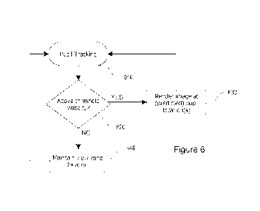
it is determined that a pupil is moving with a relatively low velocity. Figure
6 shows a
schematic example of a predictive pupil location process that may be employed
to
provide an image within a viewing zone for a user that is perceived as stable,
in
accordance with at least one embodiment. In this example, a pupil tracker
obtains a user
pupil location and/or motion at step 610, which may then be used to derive a
pupil
velocity. A processor and/or predictive engine may use this velocity to
predict whether a
pupil is moving sufficiently fast to warrant computing a new viewing
window/zone
location within which to render an image, and then perform further
computations related
to, for instance, ray tracing. The predictive engine may, in accordance with
some of the
various embodiments, compare the measured velocity to a designated threshold
velocity
at step 620. If the measured velocity is above the designated threshold, it
may be deemed
21
CA 03134669 2021-09-22
WO 2020/201999
PCT/IB2020/053035
sufficiently high to render an image to be projected within a new view zone.
In this case,
the location of the new view zone and corresponding image(s) may be chosen to
be at the
location of the pupil at the time of the position and/or velocity measurement,
or a
predicted location based on a predicted trajectory, as described above. If the
velocity is
less than the designated threshold, it may be predicted that at a future time,
a pupil's
location may still reside inside or sufficiently around the present view zone,
in which case
user experience could benefit from maintaining the current location of the
view zone and
corresponding image(s) at step 640 without re-rendering and/or performing
potentially
demanding computations. The skilled artisan will appreciate that pupil
tracking 610 may
also be performed at higher rates than the decision-making and rendering steps
of Figure
6.
[0071]
Threshold values, in accordance with various embodiments, may be chosen on
a variety of bases, non-limiting examples of which are view zone sizes or
geometries,
typical pupil speeds for a particular display system, display system
properties, specific
.. applications for which a display is typically used, or the like. For
instance, if a view zone
geometry and size, and a display rendering rate are known for a given pupil
location, a
processor may determine the speed at which a pupil would need to move in order
to
predict that the pupil will have left the view zone by the time a subsequent
rendering
could be performed. Such velocity thresholds may also be adaptive or
predictive in
nature, or may be adjustable, for instance, via a setting on the display to be
programmed
or tuned by a user. A threshold may also be set based on an empirical
determination of
user experience for a specific device, application, or setting, in accordance
with yet
another embodiment. For some embodiments, a threshold value is set to be on
the order
of 0.1 m/s.
[0072] Figure 7 shows a schematic diagram of an exemplary process for an
improved
user experience via predictive pupil determination, in accordance with another
embodiment. Reference is also made to Figure 14 in which different exemplary
viewer
pupil dynamic states, and transitions therebetween, are also illustrated. In
this example, a
pupil tracker obtains position and/or velocity data related to a pupil or
pupils. If the
determined pupil velocity is not below a certain threshold (i.e. the pupil is
determined to
22
CA 03134669 2021-09-22
WO 2020/201999
PCT/IB2020/053035
be in a "moving" mode), as determined at step 720, images will be rendered to
be
projected within a view zone in a new location in step 730, wherein the new
location may
correspond to either the latest pupil location as determined by the pupil
tracker, or at a
location predicted from related pupil location data to provide a positive
viewer
experience. If the pupil velocity is below the designated threshold (i.e. the
pupil is in a
"fixate" mode), it may be determined that the current view zone location may
be
acceptable for a pupil at a subsequent time, in which case the current view
zone location
may be maintained at step 760.
[0073] In
accordance with some embodiments, various criteria may be additionally
applied to maintain the view zone location. For example, it may be required
that the
measured or calculated pupil velocity be below the velocity threshold for a
certain
amount of time (e.g. 200 ms) as measured using a digital timer 740 (i.e. the
pupil is "pre-
fixate"). An exemplary process may then repeat the comparison of the velocity
to the
threshold at step 750, either repeatedly throughout a designated threshold
wait period, or
again at a specific later time. Other criteria or methods to filter or
otherwise provide a
reliable decision on movement may be employed without departing from the
general
scope of this disclosure. If the condition of being below the threshold is not
met at step
750, the view zone location and corresponding image(s) may then be rendered
for
projection at a new location in step 730. Otherwise, the current view zone
location may
be maintained at 760.
[0074] A
view zone location may be maintained for an amount of time that is deemed
appropriate, or until one or more conditions for determining movement 770 are
met. In
accordance with various embodiments, non-limiting examples of a condition for
movement may be that a tracked pupil location has been determined to have
crossed a
boundary of the current view zone, that a second threshold velocity, which may
or may
not be the same threshold velocity used to initiate maintaining of a view zone
location,
has been observed for the pupil, that pupil tracking data is no longer
available or has not
been received for a designated amount of time (e.g. a processor or application
has
stopped receiving tracking data for more than, for instance, 100 ms), or that
a timer has
expired (e.g. a view zone has been static for, for instance, 100 ms).
23
CA 03134669 2021-09-22
WO 2020/201999
PCT/IB2020/053035
[0075]
Optionally, and in accordance with various embodiments, another step or
steps may be employed to improve a viewer experience before returning to
rendering at a
current or predicted pupil location at step 730. A non-limiting example may be
that, given
that the pupil was recently below a designated threshold velocity, the pupil
may be
predicted to benefit from a view zone that is in a similar location to the
previous view
zone, even though a condition for movement has been met (i.e. the pupil
considered to be
in a "post-fixate" mode). For instance, if the pupils are determined to have
crossed a
boundary of the view zone in step 770, their velocity may still be low, and a
new view
zone location that would provide a positive viewing experience would lie
somewhere
between the new pupil location and the previous location. This new view zone
location
may therefore be an interpolation, as in step 780, of the previous view zone
location and
the pupil location. Non-limiting examples of an interpolation as herein
described may be
an average, a weighted average, or some other function for which a positive
viewing
experience can be predicted. The interpolation may be performed for a
designated amount
of time 790 after a condition for movement is met, or may, alternatively or in
addition, be
a function of time since the condition was met. For instance, if a condition
for movement
has been met due to a pupil location crossing a boundary of a static view
zone, the next
rendered view zone location may be a weighted average between the previous
view zone
location and the current pupil location, wherein every 10 ms, the weight of
the pupil
location in the weighted average increases in increments of 10 %, until, after
100 ms, the
location of the view zone will be that of the tracked pupil, as in step 730.
[0076] The
skilled artisan will appreciate that interpolation steps may be optionally
implemented based on the means by which a condition for movement was met. For
instance, if a pupil location has been determined to have crossed a boundary
of a static
view zone, and/or is deemed to be moving below a certain speed, an
interpolation of pupil
position and previous view zone location may be performed over 100 ms to
calculate the
next view zone location. However, if a system implementing a process herein
described
stopped receiving tracking data for 100 ms, view zone location may be updated
based
solely on new pupil location data, as in step 730, in accordance with at least
one
embodiment.
24
CA 03134669 2021-09-22
WO 2020/201999
PCT/IB2020/053035
EXAMPLE
[0077] The
following example applies the predictive pupil tracking systems and
methods described above within the context of an adjusted pixel rendering
method used
to produce an adjusted user image perception, for example, when applied to a
light field
display device. In some embodiments, the adjusted user image perception can
accommodate, to some degree, a user's reduced visual acuity. To improve
performance
and accuracy, the user's pupil location, and changes therein, can be used as
input, either
via an integrated pupil tracking device and/or engine, or via interface with
an external
device and/or engine.
[0078] For instance, the devices, displays and methods described below may
allow a
user's perception of an input image to be displayed, to be adjusted or altered
using the
light field display as a function of the user's pupil location. For instance,
in some
examples, users who would otherwise require corrective eyewear such as glasses
or
contact lenses, or again bifocals, may consume images produced by such
devices,
displays and methods in clear or improved focus without the use of such
eyewear. Other
light field display applications, such as 3D displays and the like, may also
benefit from
the solutions described herein, and thus, should be considered to fall within
the general
scope and nature of the present disclosure.
[0079] For
example, some of the herein described embodiments provide for digital
display devices, or devices encompassing such displays, for use by users
having reduced
visual acuity, whereby images ultimately rendered by such devices can be
dynamically
processed to accommodate the user's reduced visual acuity so that they may
consume
rendered images without the use of corrective eyewear, as would otherwise be
required.
As noted above, embodiments are not to be limited as such as the notions and
solutions
described herein may also be applied to other technologies in which a user's
perception
of an input image to be displayed can be altered or adjusted via the light
field display.
[0080]
Generally, digital displays as considered herein will comprise a set of image
rendering pixels and an array of light-field shaping elements, also herein
referred to
interchangeably as a light field shaping layer, disposed at a preset distance
therefrom so
CA 03134669 2021-09-22
WO 2020/201999
PCT/IB2020/053035
to controllably shape or influence a light field emanating therefrom. For
instance, each
light field shaping layer will be defined by an array of optical elements
centered over a
corresponding subset of the display's pixel array to optically influence a
light field
emanating therefrom and thereby govern a projection thereof from the display
medium
toward the user, for instance, providing some control over how each pixel or
pixel group
will be viewed by the viewer's eye(s). As will be further detailed below,
arrayed optical
elements may include, but are not limited to, lenslets, microlenses or other
such
diffractive optical elements that together form, for example, a lenslet array;
pinholes or
like apertures or windows that together form, for example, a parallax or like
barrier;
concentrically patterned barriers, e.g. cut outs and/or windows, such as a to
define a
Fresnel zone plate or optical sieve, for example, and that together form a
diffractive
optical barrier (as described, for example, in Applicant's co-pending U.S.
Application
Serial No. 15/910,908, the entire contents of which are hereby incorporated
herein by
reference); and/or a combination thereof, such as for example, a lenslet array
whose
respective lenses or lenslets are partially shadowed or barriered around a
periphery
thereof so to combine the refractive properties of the lenslet with some of
the advantages
provided by a pinhole barrier.
[0081] In
operation, the display device will also generally invoke a hardware
processor operable on image pixel (or subpixel) data for an image to be
displayed to
output corrected or adjusted image pixel data to be rendered as a function of
a stored
characteristic of the light field shaping layer (e.g. layer distance from
display screen,
distance between optical elements (pitch), absolute relative location of each
pixel or
subpixel to a corresponding optical element, properties of the optical
elements (size,
diffractive and/or refractive properties, etc.), or other such properties, and
a selected
vision correction or adjustment parameter related to the user's reduced visual
acuity or
intended viewing experience. While light field display characteristics will
generally
remain static for a given implementation (i.e. a given shaping layer will be
used and set
for each device irrespective of the user), image processing can, in some
embodiments, be
dynamically adjusted as a function of the user's visual acuity or intended
application so
to actively adjust a distance of a virtual image plane, or perceived image on
the user's
retinal plane given a quantified user eye focus or like optical aberration(s),
induced upon
26
CA 03134669 2021-09-22
WO 2020/201999
PCT/IB2020/053035
rendering the corrected/adjusted image pixel data via the static optical
layer, for example,
or otherwise actively adjust image processing parameters as may be considered,
for
example, when implementing a viewer-adaptive pre-filtering algorithm or like
approach
(e.g. compressive light field optimization), so to at least in part govern an
image
.. perceived by the user's eye(s) given pixel or subpixel-specific light
visible thereby
through the layer.
[0082]
Accordingly, a given device may be adapted to compensate for different
visual acuity levels and thus accommodate different users and/or uses. For
instance, a
particular device may be configured to implement and/or render an interactive
graphical
user interface (GUI) that incorporates a dynamic vision correction scaling
function that
dynamically adjusts one or more designated vision correction parameter(s) in
real-time in
response to a designated user interaction therewith via the GUI. For example,
a dynamic
vision correction scaling function may comprise a graphically rendered scaling
function
controlled by a (continuous or discrete) user slide motion or like operation,
whereby the
GUI can be configured to capture and translate a user's given slide motion
operation to a
corresponding adjustment to the designated vision correction parameter(s)
scalable with a
degree of the user's given slide motion operation. These and other examples
are
described in Applicant's co-pending U.S. Patent Application Serial No.
15/246,255, the
entire contents of which are hereby incorporated herein by reference.
[0083] In general, a digital display device as considered herein may
include, but is
not limited to, smartphones, tablets, e-readers, watches, televisions, GPS
devices, laptops,
desktop computer monitors, televisions, smart televisions, handheld video game
consoles
and controllers, vehicular dashboard and/or entertainment displays, ticketing
or shopping
kiosks, point-of-sale (POS) systems, workstations, or the like.
[0084] Generally, the device will comprise a processing unit, a digital
display, and
internal memory. The display can be an LCD screen, a monitor, a plasma display
panel,
an LED or OLED screen, or any other type of digital display defined by a set
of pixels for
rendering a pixelated image or other like media or information. Internal
memory can be
any form of electronic storage, including a disk drive, optical drive, read-
only memory,
27
CA 03134669 2021-09-22
WO 2020/201999
PCT/IB2020/053035
random-access memory, or flash memory, to name a few examples. For
illustrative
purposes, memory has stored in it a vision correction or image adjustment
application
and/or a predictive pupil tracking engine, though various methods and
techniques may be
implemented to provide computer-readable code and instructions for execution
by the
processing unit in order to process pixel data for an image to be rendered in
producing
corrected pixel data amenable to producing a corrected image accommodating the
user's
reduced visual acuity (e.g. stored and executable image correction
application, tool,
utility or engine, etc.). Other components of the electronic device may
optionally include,
but are not limited to, one or more rear and/or front-facing camera(s) (e.g.
for onboard
pupil tracking capabilities), pupil tracking light source, an accelerometer
and/or other
device positioning/orientation devices capable of determining the tilt and/or
orientation of
electronic device, or the like.
[0085] For
example, the electronic device, or related environment (e.g. within the
context of a desktop workstation, vehicular console/dashboard, gaming or e-
learning
station, multimedia display room, etc.) may include further hardware, firmware
and/or
software components and/or modules to deliver complementary and/or cooperative
features, functions and/or services. For example, as previously noted, a
pupil/eye tracking
system may be integrally or cooperatively implemented to improve or enhance
corrective
image rendering by tracking a location of the user's eye(s)/pupil(s) (e.g.
both or one, e.g.
dominant, eye(s)) and adjusting light field corrections accordingly. For
instance, the
device may include, integrated therein or interfacing therewith, one or more
eye/pupil
tracking light sources, such as one or more infrared (IR) or near-IR (NIR)
light source(s)
to accommodate operation in limited ambient light conditions, leverage retinal
retro-
reflections, invoke corneal reflection, and/or other such considerations. For
instance,
different IR/NIR pupil tracking techniques may employ one or more (e.g.
arrayed)
directed or broad illumination light sources to stimulate retinal retro-
reflection and/or
corneal reflection in identifying and tracking a pupil location. Other
techniques may
employ ambient or IR/NIR light-based machine vision and facial recognition
techniques
to otherwise locate and track the user's eye(s)/pupil(s). To do so, one or
more
corresponding (e.g. visible, IR/NIR) cameras may be deployed to capture
eye/pupil
tracking signals that can be processed, using various image/sensor data
processing
28
CA 03134669 2021-09-22
WO 2020/201999
PCT/IB2020/053035
techniques, to map a 3D location of the user's eye(s)/pupil(s). In the context
of a mobile
device, such as a mobile phone, such eye/pupil tracking hardware/software may
be
integral to the device, for instance, operating in concert with integrated
components such
as one or more front facing camera(s), onboard IR/NIR light source(s) and the
like. In
other user environments, such as in a vehicular environment, eye/pupil
tracking hardware
may be further distributed within the environment, such as dash, console,
ceiling,
windshield, mirror or similarly-mounted camera(s), light sources, etc.
[0086]
Furthermore, the electronic device in this example will comprise a light field
shaping layer (LFSL) or array of light field shaping elements overlaid atop a
display
thereof and spaced therefrom (e.g. via an integrated or distinct spacer) or
other such
means as may be readily apparent to the skilled artisan. For the sake of
illustration, the
following examples will be described within the context of a light field
shaping layer
defined, at least in part, by a lenslet array comprising an array of
microlenses (also
interchangeably referred to herein as lenslets) that are each disposed at a
distance from a
corresponding subset of image rendering pixels in an underlying digital
display. It will be
appreciated that while a light field shaping layer may be manufactured and
disposed as a
digital screen overlay, other integrated concepts may also be considered, for
example,
where light field shaping elements are integrally formed or manufactured
within a digital
screen's integral components such as a textured or masked glass plate, beam-
shaping
light sources or like component. Accordingly, each lenslet will predictively
shape light
emanating from these pixel subsets to at least partially govern light rays
being projected
toward the user by the display device. As noted above, other light field
shaping layers
may also be considered herein without departing from the general scope and
nature of the
present disclosure, whereby light field shaping will be understood by the
person of
ordinary skill in the art to reference measures by which light, that would
otherwise
emanate indiscriminately (i.e. isotropically) from each pixel group, is
deliberately
controlled to define predictable light rays that can be traced between the
user and the
device's pixels through the shaping layer.
[0087] For
greater clarity, a light field is generally defined as a vector function that
describes the amount of light flowing in every direction through every point
in space. In
29
CA 03134669 2021-09-22
WO 2020/201999
PCT/IB2020/053035
other words, anything that produces or reflects light has an associated light
field. The
embodiments described herein produce light fields from an object that are not
"natural"
vector functions one would expect to observe from that object. This gives it
the ability to
emulate the "natural" light fields of objects that do not physically exist,
such as a virtual
display located far behind the light field display, which will be referred to
now as the
'virtual image'. As noted in the examples below, in some embodiments, light
field
rendering may be adjusted to effectively generate a virtual image on a virtual
image plane
that is set at a designated distance from an input user pupil location, for
example, so to
effective push back, or move forward, a perceived image relative to the
display device in
accommodating a user's reduced visual acuity (e.g. minimum or maximum viewing
distance). In yet other embodiments, light field rendering may rather or
alternatively seek
to map the input image on a retinal plane of the user, taking into account
visual
aberrations, so to adaptively adjust rendering of the input image on the
display device to
produce the mapped effect. Namely, where the unadjusted input image would
otherwise
typically come into focus in front of or behind the retinal plane (and/or be
subject to other
optical aberrations), this approach allows to map the intended image on the
retinal plane
and work therefrom to address designated optical aberrations accordingly.
Using this
approach, the device may further computationally interpret and compute virtual
image
distances tending toward infinity, for example, for extreme cases of
presbyopia. This
approach may also more readily allow, as will be appreciated by the below
description,
for adaptability to other visual aberrations that may not be as readily
modeled using a
virtual image and image plane implementation. In both of these examples, and
like
embodiments, the input image is digitally mapped to an adjusted image plane
(e.g. virtual
image plane or retinal plane) designated to provide the user with a designated
image
perception adjustment that at least partially addresses designated visual
aberrations.
Naturally, while visual aberrations may be addressed using these approaches,
other visual
effects may also be implemented using similar techniques.
[0088]
With reference to Figures 8 to 10, and in accordance with one embodiment, an
exemplary, computationally implemented, ray-tracing method for rendering an
adjusted
image perception via a light field shaping layer (LFSL) or array of light
field shaping
elements, for example a computationally corrected image that accommodates for
the
CA 03134669 2021-09-22
WO 2020/201999
PCT/IB2020/053035
user's reduced visual acuity, will now be described. In this exemplary
embodiment, a set
of constant parameters 1102 may be pre-determined. These may include, for
example,
any data that are not expected to significantly change during a user's viewing
session, for
instance, which are generally based on the physical and functional
characteristics of the
display for which the method is to be implemented, as will be explained below.
Similarly,
every iteration of the rendering algorithm may use a set of input variables
1104 which are
expected to change either at each rendering iteration or at least between each
user's
viewing session.
[0089] As
illustrated in Figure 9, the list of constant parameters 1102 may include,
without limitations, the distance 1204 between the display and the LFSL, the
in-plane
rotation angle 1206 between the display and LFSL frames of reference, the
display
resolution 1208, the size of each individual pixel 1210, the optical LFSL
geometry 1212,
the size of each optical element 1214 within the LFSL and optionally the
subpixel layout
1216 of the display. Moreover, both the display resolution 1208 and the size
of each
individual pixel 1210 may be used to pre-determine both the absolute size of
the display
in real units (i.e. in mm) and the three-dimensional position of each pixel
within the
display. In some embodiments where the subpixel layout 1216 is available, the
position
within the display of each subpixel may also be pre-determined. These three-
dimensional
location/positions are usually calculated using a given frame of reference
located
somewhere within the plane of the display, for example a corner or the middle
of the
display, although other reference points may be chosen. Concerning the optical
layer
geometry 1212, different geometries may be considered, for example a hexagonal
geometry such as the one shown in Figure 10. Finally, by combining the
distance 1204,
the rotation angle 1206, and the geometry 1212 with the optical element size
1214, it is
possible to similarly pre-determine the three-dimensional location/position of
each optical
element center with respect to the display's same frame of reference.
[0090]
Figure 10, meanwhile, illustratively lists an exemplary set of input variables
1104 for method 1100, which may include any input data fed into method 1100
that may
reasonably change during a user's single viewing session, and may thus include
without
limitation: the image(s) to be displayed 1306 (e.g. pixel data such as on/off,
colour,
31
CA 03134669 2021-09-22
WO 2020/201999
PCT/IB2020/053035
brightness, etc.) and the minimum reading distance 1310 (e.g. one or more
parameters
representative of the user's reduced visual acuity or condition). In some
embodiments,
the eye depth 1314 may also be used.
[0091] The
image data 1306, for example, may be representative of one or more
digital images to be displayed with the digital pixel display. This image may
generally be
encoded in any data format used to store digital images known in the art. In
some
embodiments, images 1306 to be displayed may change at a given framerate.
[0092]
Following from the above-described embodiments, a further input variable
includes the three-dimensional pupil location 1308, and optional pupil size
1312. As
detailed above, the input pupil location in this sequence may include a
current pupil
location as output from a corresponding pupil tracking system, or a predicted
pupil
location, for example, when the process 1100 is implemented at a higher
refresh rate than
that otherwise available from the pupil tracking system, for instance, or if a
pupil is
moving sufficiently slowly that view zone re-rendering may not be necessary.
As will be
appreciated by the skilled artisan, the input pupil location 1308 may be
provided by an
external pupil tracking engine and/or device 1305, or again provided by an
internal
engine and/or integrated devices, depending the application and implementation
at hand.
For example, a self-contained digital display device such as a mobile phone,
tablet, laptop
computer, digital television, or the like may include integrated hardware to
provide real
time pupil tracking capabilities, such as an integrated camera and machine
vision-based
pupil tracking engine; integrated light source, camera and glint-based pupil
tracking
engine; and/or a combination thereof. In other embodiments or implementations,
external
pupil tracking hardware and/or firmware may be leveraged to provide a real
time pupil
location. For example, a vehicular dashboard, control or entertainment display
may
interface with an external camera(s) and/or pupil tracking hardware to produce
a similar
effect. Naturally, the integrated or distributed nature of the various
hardware, firmware
and/or software components required to execute the predictive pupil tracking
functionalities described herein may vary for different applications,
implementations and
solution at hand.
32
CA 03134669 2021-09-22
WO 2020/201999
PCT/IB2020/053035
[0093] The
pupil location 1308, in one embodiment, is the three-dimensional
coordinates of at least one the user's pupils' center with respect to a given
reference
frame, for example a point on the device or display. This pupil location 1308
may be
derived from any eye/pupil tracking method known in the art. In some
embodiments, the
pupil location 1308 may be determined prior to any new iteration of the
rendering
algorithm, or in other cases, at a lower framerate. In some embodiments, only
the pupil
location of a single user's eye may be determined, for example the user's
dominant eye
(i.e. the one that is primarily relied upon by the user). In some embodiments,
this
position, and particularly the pupil distance to the screen may otherwise or
additionally
be rather approximated or adjusted based on other contextual or environmental
parameters, such as an average or preset user distance to the screen (e.g.
typical reading
distance for a given user or group of users; stored, set or adjustable driver
distance in a
vehicular environment; etc.).
[0094] In
the illustrated embodiment, the minimum reading distance 1310 is defined
as the minimal focus distance for reading that the user's eye(s) may be able
to
accommodate (i.e. able to view without discomfort). In some embodiments,
different
values of the minimum reading distance 1310 associated with different users
may be
entered, for example, as can other adaptive vision correction parameters be
considered
depending on the application at hand and vision correction being addressed.
[0095] With added reference to Figures 11A to 11C, once parameters 1102 and
variables 1104 have been set, the method of Figure 13 then proceeds with step
1106, in
which the minimum reading distance 1310 (and/or related parameters) is used to
compute
the position of a virtual (adjusted) image plane 1405 with respect to the
device's display,
followed by step 1108 wherein the size of image 1306 is scaled within the
image plane
1405 to ensure that it correctly fills the pixel display 1401 when viewed by
the distant
user. This is illustrated in Figure 11A, which shows a diagram of the relative
positioning
of the user's pupil 1415, the light field shaping layer 1403, the pixel
display 1401 and the
virtual image plane 1405. In this example, the size of image 1306 in image
plane 1405 is
increased to avoid having the image as perceived by the user appear smaller
than the
display's size.
33
CA 03134669 2021-09-22
WO 2020/201999
PCT/IB2020/053035
[0096] An
exemplary ray-tracing methodology is described in steps 1110 to 1128 of
Figure 8, at the end of which the output color of each pixel of pixel display
1401 is
known so as to virtually reproduce the light field emanating from an image
1306
positioned at the virtual image plane 1405. In Figure 8, these steps are
illustrated in a
loop over each pixel in pixel display 1401, so that each of steps 1110 to 1126
describes
the computations done for each individual pixel. However, in some embodiments,
these
computations need not be executed sequentially, but rather, steps 1110 to 1128
may
executed in parallel for each pixel or a subset of pixels at the same time.
Indeed, as will
be discussed below, this exemplary method is well suited to vectorization and
implementation on highly parallel processing architectures such as GPUs.
[0097] As
illustrated in Figures 11 A to 11C, in step 1110, for a given pixel 1409 in
pixel display 1401, a trial vector 1413 is first generated from the pixel's
position to the
(actual or predicted) center position 1417 of pupil 1415. This is followed in
step 1112 by
calculating the intersection point 1411 of vector 1413 with the LFSL 1403.
[0098] The method then finds, in step 1114, the coordinates of the center
1416 of the
LFSL optical element closest to intersection point 1411. Once the position of
the center
1416 of the optical element is known, in step 1116, a normalized unit ray
vector is
generated from drawing and normalizing a vector 1423 drawn from center
position 1416
to pixel 1409. This unit ray vector generally approximates the direction of
the light field
emanating from pixel 1409 through this particular light field element, for
instance, when
considering a parallax barrier aperture or lenslet array (i.e. where the path
of light
travelling through the center of a given lenslet is not deviated by this
lenslet). Further
computation may be required when addressing more complex light shaping
elements, as
will be appreciated by the skilled artisan. The direction of this ray vector
will be used to
.. find the portion of image 1306, and thus the associated color, represented
by pixel 1409.
But first, in step 1118, this ray vector is projected backwards to the plane
of pupil 1415,
and then in step 1120, the method verifies that the projected ray vector 1425
is still within
pupil 1415 (i.e. that the user can still "see" it). Once the intersection
position, for example
location 1431 in Figure 11B, of projected ray vector 1425 with the pupil plane
is known,
the distance between the pupil center 1417 and the intersection point 1431 may
be
34
CA 03134669 2021-09-22
WO 2020/201999
PCT/IB2020/053035
calculated to determine if the deviation is acceptable, for example by using a
pre-
determined pupil size and verifying how far the projected ray vector is from
the pupil
center.
[0099] If
this deviation is deemed to be too large (i.e. light emanating from pixel
1409 channeled through optical element 1416 is not perceived by pupil 1415),
then in
step 1122, the method flags pixel 1409 as unnecessary and to simply be turned
off or
render a black color. Otherwise, as shown in Figure 11C, in step 1124, the ray
vector is
projected once more towards virtual image plane 1405 to find the position of
the
intersection point 1423 on image 1306. Then in step 1126, pixel 1409 is
flagged as
having the color value associated with the portion of image 1306 at
intersection point
1423.
[00100] In some embodiments, method 1100 is modified so that at step 1120,
instead
of having a binary choice between the ray vector hitting the pupil or not, one
or more
smooth interpolation function (i.e. linear interpolation, Hermite
interpolation or similar)
are used to quantify how far or how close the intersection point 1431 is to
the pupil center
1417 by outputting a corresponding continuous value between 1 or 0. For
example, the
assigned value is equal to 1 substantially close to pupil center 1417 and
gradually change
to 0 as the intersection point 1431 substantially approaches the pupil edges
or beyond. In
this case, the branch containing step 1122 is ignored and step 1220 continues
to step
1124. At step 1126, the pixel color value assigned to pixel 1409 is chosen to
be
somewhere between the full color value of the portion of image 1306 at
intersection point
1423 or black, depending on the value of the interpolation function used at
step 1120 (1
or 0).
[00101] In yet other embodiments, pixels found to illuminate a designated area
around
the pupil may still be rendered, for example, to produce a buffer zone to
accommodate
small movements in pupil location, for example, or again, to address potential
inaccuracies, misalignments or to create a better user experience.
[00102] In some embodiments, steps 1118, 1120 and 1122 may be avoided
completely, the method instead going directly from step 1116 to step 1124. In
such an
CA 03134669 2021-09-22
WO 2020/201999
PCT/IB2020/053035
exemplary embodiment, no check is made that the ray vector hits the pupil or
not, but
instead the method assumes that it always does.
[00103] Once the output colors of all pixels have been determined, these are
finally
rendered in step 1130 by pixel display 1401 to be viewed by the user,
therefore
presenting a light field corrected image. In the case of a single static
image, the method
may stop here. However, new input variables may be entered and the image may
be
refreshed at any desired frequency, for example because the user's pupil moves
as a
function of time and/or because instead of a single image a series of images
are displayed
at a given framerate.
[00104] With reference to Figures 12 and 13A to 13D, and in accordance with
one
embodiment, another exemplary computationally implemented ray-tracing method
for
rendering an adjusted image via the light field shaping layer (LFSL) that
accommodates
for the user's reduced visual acuity, for example, will now be described. In
this
embodiment, the adjusted image portion associated with a given pixel/subpixel
is
computed (mapped) on the retina plane instead of the virtual image plane
considered in
the above example, again in order to provide the user with a designated image
perception
adjustment. Therefore, the currently discussed exemplary embodiment shares
some steps
with the method of Figure 8. Indeed, a set of constant parameters 1402 may
also be pre-
determined. These may include, for example, any data that are not expected to
significantly change during a user's viewing session, for instance, which are
generally
based on the physical and functional characteristics of the display for which
the method is
to be implemented, as will be explained below. Similarly, every iteration of
the rendering
algorithm may use a set of input variables 1404 which are expected to change
either at
each rendering iteration or at least between each user viewing session. The
list of possible
variables and constants is substantially the same as the one disclosed in
Figures 9 and 10
and will thus not be replicated here.
[00105] Once parameters 1402 and variables 1404 have been set, this second
exemplary ray-tracing methodology proceeds from steps 1910 to 1936, at the end
of
which the output color of each pixel of the pixel display is known so as to
virtually
36
CA 03134669 2021-09-22
WO 2020/201999
PCT/IB2020/053035
reproduce the light field emanating from an image perceived to be positioned
at the
correct or adjusted image distance, in one example, so to allow the user to
properly focus
on this adjusted image (i.e. having a focused image projected on the user's
retina) despite
a quantified visual aberration. In Figure 12, these steps are illustrated in a
loop over each
pixel in pixel display 1401, so that each of steps 1910 to 1934 describes the
computations
done for each individual pixel. However, in some embodiments, these
computations need
not be executed sequentially, but rather, steps 1910 to 1934 may be executed
in parallel
for each pixel or a subset of pixels at the same time. Indeed, as will be
discussed below,
this second exemplary method is also well suited to vectorization and
implementation on
highly parallel processing architectures such as GPUs.
[00106] Referencing once more Figure 11A, in step 1910 (as in step 1110), for
a given
pixel in pixel display 1401, a trial vector 1413 is first generated from the
pixel's position
to (actual or predicted) pupil center 1417 of the user's pupil 1415. This is
followed in step
1912 by calculating the intersection point of vector 1413 with optical layer
1403.
.. [00107] From there, in step 1914, the coordinates of the optical element
center 1416
closest to intersection point 1411 are determined. This step may be
computationally
intensive and will be discussed in more depth below. As shown in Figure 11B,
once the
position of the optical element center 1416 is known, in step 1916, a
normalized unit ray
vector is generated from drawing and normalizing a vector 1423 drawn from
optical
element center 1416 to pixel 1409. This unit ray vector generally approximates
the
direction of the light field emanating from pixel 1409 through this particular
light field
element, for instance, when considering a parallax barrier aperture or lenslet
array (i.e.
where the path of light travelling through the center of a given lenslet is
not deviated by
this lenslet). Further computation may be required when addressing more
complex light
shaping elements, as will be appreciated by the skilled artisan. In step 1918,
this ray
vector is projected backwards to pupil 1415, and then in step 1920, the method
ensures
that the projected ray vector 1425 is still within pupil 1415 (i.e. that the
user can still
"see" it). Once the intersection position, for example location 1431 in Figure
11B, of
projected ray vector 1425 with the pupil plane is known, the distance between
the pupil
center 1417 and the intersection point 1431 may be calculated to determine if
the
37
CA 03134669 2021-09-22
WO 2020/201999
PCT/IB2020/053035
deviation is acceptable, for example by using a pre-determined pupil size and
verifying
how far the projected ray vector is from the pupil center.
[00108] Now referring to Figures 13A to 13D, steps 1921 to 1929 of method 1900
will
be described. Once optical element center 1416 of the relevant optical unit
has been
determined, at step 1921, a vector 2004 is drawn from optical element center
1416 to
(actual or predicted) pupil center 1417. Then, in step 1923, vector 2004 is
projected
further behind the pupil plane onto focal plane 2006 (location where any light
rays
originating from optical layer 1403 would be focused by the eye's lens) to
locate focus
point 2008. For a user with perfect vision, focal plane 2006 would be located
at the same
location as retina plane 2010, but in this example, focal plane 2006 is
located behind
retina plane 2006, which would be expected for a user with some form of
farsightedness.
The position of focal plane 2006 may be derived from the user's minimum
reading
distance 1310, for example, by deriving therefrom the focal length of the
user's eye.
Other manually input or computationally or dynamically adjustable means may
also or
alternatively be considered to quantify this parameter.
[00109] The skilled artisan will note that any light ray originating from
optical element
center 1416, no matter its orientation, will also be focused onto focus point
2008, to a
first approximation. Therefore, the location on retina plane (2012) onto which
light
entering the pupil at intersection point 1431 will converge may be
approximated by
drawing a straight line between intersection point 1431 where ray vector 1425
hits the
pupil 1415 and focus point 2008 on focal plane 2006. The intersection of this
line with
retina plane 2010 (retina image point 2012) is thus the location on the user's
retina
corresponding to the image portion that will be reproduced by corresponding
pixel 1409
as perceived by the user. Therefore, by comparing the relative position of
retina point
2012 with the overall position of the projected image on the retina plane
2010, the
relevant adjusted image portion associated with pixel 1409 may be computed.
[00110] To do so, at step 1927, the corresponding projected image center
position on
retina plane 2010 is calculated. Vector 2016 is generated originating from the
center
position of display 1401 (display center position 2018) and passing through
pupil center
38
CA 03134669 2021-09-22
WO 2020/201999
PCT/IB2020/053035
1417. Vector 2016 is projected beyond the pupil plane onto retina plane 2010,
wherein
the associated intersection point gives the location of the corresponding
retina image
center 2020 on retina plane 2010. The skilled technician will understand that
step 1927
could be performed at any moment prior to step 1929, once the relative pupil
center
.. location 1417 is known in input variables step 1904. Once image center 2020
is known,
one can then find the corresponding image portion of the selected
pixel/subpixel at step
1929 by calculating the x/y coordinates of retina image point 2012 relative to
retina
image center 2020 on the retina, scaled to the x/y retina image size 2031.
[00111] This retina image size 2031 may be computed by calculating the
magnification of an individual pixel on retina plane 2010, for example, which
may be
approximately equal to the x or y dimension of an individual pixel multiplied
by the eye
depth 1314 and divided by the absolute value of the distance to the eye (i.e.
the
magnification of pixel image size from the eye lens). Similarly, for
comparison purposes,
the input image is also scaled by the image x/y dimensions to produce a
corresponding
scaled input image 2064. Both the scaled input image and scaled retina image
should
have a width and height between -0.5 to 0.5 units, enabling a direct
comparison between
a point on the scaled retina image 2010 and the corresponding scaled input
image 2064,
as shown in Figure 13D.
[00112] From there, the image portion position 2041 relative to retina image
center
.. position 2043 in the scaled coordinates (scaled input image 2064)
corresponds to the
inverse (because the image on the retina is inverted) scaled coordinates of
retina image
point 2012 with respect to retina image center 2020. The associated color with
image
portion position 2041 is therefrom extracted and associated with pixel 1409.
[00113] In some embodiments, method 1900 may be modified so that at step 1920,
instead of having a binary choice between the ray vector hitting the pupil or
not, one or
more smooth interpolation function (i.e. linear interpolation, Hermite
interpolation or
similar) are used to quantify how far or how close the intersection point 1431
is to the
pupil center 1417 by outputting a corresponding continuous value between 1 or
0. For
example, the assigned value is equal to 1 substantially close to pupil center
1417 and
39
CA 03134669 2021-09-22
WO 2020/201999
PCT/IB2020/053035
gradually change to 0 as the intersection point 1431 substantially approaches
the pupil
edges or beyond. In this case, the branch containing step 1122 is ignored and
step 1920
continues to step 1124. At step 1931, the pixel color value assigned to pixel
1409 is
chosen to be somewhere between the full color value of the portion of image
1306 at
intersection point 1423 or black, depending on the value of the interpolation
function
used at step 1920 (1 or 0).
[00114] In yet other embodiments, pixels found to illuminate a designated area
around
the pupil may still be rendered, for example, to produce a buffer zone to
accommodate
small movements in pupil location, for example, or again, to address potential
inaccuracies or misalignments.
[00115] Once the output colors of all pixels in the display have been
determined
(check at step 1934 is true), these are finally rendered in step 1936 by pixel
display 1401
to be viewed by the user, therefore presenting a light field corrected image.
In the case of
a single static image, the method may stop here. However, new input variables
may be
entered and the image may be refreshed at any desired frequency, for example
because
the user's pupil moves as a function of time and/or because instead of a
single image a
series of images are displayed at a given framerate.
[00116] As will be appreciated by the skilled artisan, selection of the
adjusted image
plane onto which to map the input image in order to adjust a user perception
of this input
image allows for different ray tracing approaches to solving a similar
challenge, that is of
creating an adjusted image using the light field display that can provide an
adjusted user
perception, such as addressing a user's reduce visual acuity. While mapping
the input
image to a virtual image plane set at a designated minimum (or maximum)
comfortable
viewing distance can provide one solution, the alternate solution may allow
accommodation of different or possibly more extreme visual aberrations. For
example,
where a virtual image is ideally pushed to infinity (or effectively so),
computation of an
infinite distance becomes problematic. However, by designating the adjusted
image plane
as the retinal plane, the illustrative process of Figure 12 can accommodate
the formation
of a virtual image effectively set at infinity without invoking such
computational
CA 03134669 2021-09-22
WO 2020/201999
PCT/IB2020/053035
challenges. Likewise, while first order focal length aberrations are
illustratively described
with reference to Figure 12, higher order or other optical anomalies may be
considered
within the present context, whereby a desired retinal image is mapped out and
traced
while accounting for the user's optical aberration(s) so to compute adjusted
pixel data to
be rendered in producing that image. These and other such considerations
should be
readily apparent to the skilled artisan.
[00117] While the computations involved in the above described ray-tracing
algorithms (steps 1110 to 1128 of Figure 8 or steps 1920 to 1934 of Figure 12)
may be
done on general CPUs, it may be advantageous to use highly parallel
programming
schemes to speed up such computations. While in some embodiments, standard
parallel
programming libraries such as Message Passing Interface (MPI) or OPENMP may be
used to accelerate the light field rendering via a general-purpose CPU, the
light field
computations described above are especially tailored to take advantage of
graphical
processing units (GPU), which are specifically tailored for massively parallel
computations. Indeed, modern GPU chips are characterized by the very large
number of
processing cores, and an instruction set that is commonly optimized for
graphics. In
typical use, each core is dedicated to a small neighborhood of pixel values
within an
image, e.g., to perform processing that applies a visual effect, such as
shading, fog, affine
transformation, etc. GPUs are usually also optimized to accelerate exchange of
image
data between such processing cores and associated memory, such as RGB frame
buffers.
Furthermore, smartphones are increasingly being equipped with powerful GPUs to
speed
the rendering of complex screen displays, e.g., for gaming, video, and other
image-
intensive applications. Several programming frameworks and languages tailored
for
programming on GPUs include, but are not limited to, CUDA, OpenCL, OpenGL
Shader
Language (GLSL), High-Level Shader Language (HLSL) or similar. However, using
GPUs efficiently may be challenging and thus require creative steps to
leverage their
capabilities, as will be discussed below.
[00118] While the present disclosure describes various embodiments for
illustrative
purposes, such description is not intended to be limited to such embodiments.
On the
contrary, the applicant's teachings described and illustrated herein encompass
various
41
CA 03134669 2021-09-22
WO 2020/201999
PCT/IB2020/053035
alternatives, modifications, and equivalents, without departing from the
embodiments, the
general scope of which is defined in the appended claims. Except to the extent
necessary
or inherent in the processes themselves, no particular order to steps or
stages of methods
or processes described in this disclosure is intended or implied. In many
cases the order
of process steps may be varied without changing the purpose, effect, or import
of the
methods described.
[00119] Information as herein shown and described in detail is fully capable
of
attaining the above-described object of the present disclosure, the presently
preferred
embodiment of the present disclosure, and is, thus, representative of the
subject matter
which is broadly contemplated by the present disclosure. The scope of the
present
disclosure fully encompasses other embodiments which may become apparent to
those
skilled in the art, and is to be limited, accordingly, by nothing other than
the appended
claims, wherein any reference to an element being made in the singular is not
intended
to mean "one and only one" unless explicitly so stated, but rather "one or
more." All
structural and functional equivalents to the elements of the above-described
preferred
embodiment and additional embodiments as regarded by those of ordinary skill
in the art
are hereby expressly incorporated by reference and are intended to be
encompassed by
the present claims. Moreover, no requirement exists for a system or method to
address
each and every problem sought to be resolved by the present disclosure, for
such to be
encompassed by the present claims. Furthermore, no element, component, or
method
step in the present disclosure is intended to be dedicated to the public
regardless of
whether the element, component, or method step is explicitly recited in the
claims.
However, that various changes and modifications in form, material, work-piece,
and
fabrication material detail may be made, without departing from the spirit and
scope of the
present disclosure, as set forth in the appended claims, as may be apparent to
those of
ordinary skill in the art, are also encompassed by the disclosure.
42