Note: Descriptions are shown in the official language in which they were submitted.
AUTOMATIC GUIDED VEHICLE
TECHNICAL FIELD
The present invention belongs generally to the field of industry and storage
devices
automatically guided by means of routes programmed for the movement of goods
within
warehouses and production lines. In particular, it relates to an automatic
guided vehicle
having the capacity of moving product, in a secure manner, from a point "A" to
a point "B"
by means of the implementation of positioning and safety systems.
BACKGROUND OF THE INVENTION
AGVs (automatic guided vehicles) are autonomous vehicles, without a driver,
which realise
the supply of materials in sequenced processes. By means of this the logistics
of
companies will be more secure and almost free of errors which diminish
productivity and
efficacy.
The autonomy of this type of transport within the interior of a building
permits the transport
of loads to the position thereof, programming the route which it must follow
by means of a
traffic control centre which permits the vehicle to circulate and not collide
with others
realising this work, materials, or workers present at that moment. In order to
comply with
the principal characteristic thereof of navigating or circulating as an
autonomous vehicle
not requiring the intervention of a human being as driver of the same, these
vehicles
dispose of diverse guiding systems and of a complex system of control and
management,
permitting the differentiation of two large groups: those the system of
management and
control whereof does not communicate with the environment wherein they move,
that is to
say that they are autonomous and the system solely manages the fleet of
vehicles obliging
them work in an automatic manner and without interacting with the environment,
or
complex AGV systems wherein fluid communications with the environment are
habitual
and fundamental, by virtue of the fact that through these communications the
orders of the
vehicles and the movements to be realised are managed at all times,
communicating with
Date Recue/Date Received 2021-08-24
2
plant maintenance systems, automatic doors, automatic warehouses, and with the
company's management software, whether of the type ERP, WMS, etc.
Automatic guided vehicles (AGVs) move along routes programmed for the movement
of
goods within warehouses and production lines, these vehicles making use of
navigation
sensors together with references installed in the warehouses or production
lines, they
being equipped with safety devices such as safety laser scanners in order to
comply with
the industrial and machinery safety regulations of the country wherein they
are marketed,
by virtue of the high degree of interaction thereof with the personnel of the
warehouses or
production line.
There presently exist several proposals in relation to automatic guided
vehicles. For
example, the Japanese patent JP 3341490 B2 reveals a system and automatic
guided
vehicle equipped with a means of control and a journey route layout map stored
in a prior
manner in this means of control. When each AGV receives a transport command in
a
wireless manner from the controller on the land side, the driving wheels are
operated and
the distance of displacement is monitored by means of an encoder detecting the
number
of revolutions of the driving wheels, and the vehicle travels to the
destination position in
accordance with the design of the map. It is designed to function in an
entirely
autonomous manner. However, in spite of the fact that the vehicle is fully
autonomous,
there exists the possibility that the vehicle may deviate slightly from the
predetermined
route due to the sliding of the driving wheels. As a consequence thereof, a
laser light is
emitted from the laser light emitting/receiving means towards a plurality of
reflectors, such
as a reflective tape provided upon the surface of the wall of the displacement
space (this
installation position is also stored in a prior manner in the means of
control). The position
of the subject is assessed by triangulation as a function of the quantity
(direction of
distance to reflector A) and the direction of the reflected light projected
from the reflector A
and corrects the deviation from the predetermined route to the objective
position with
precision. The present invention also makes use of positioning sensors
however, differing
from the Japanese patent, it additionally utilises a navigation and safety
sensor to maintain
the vehicle within the preestablished trajectory and furthermore makes use of
safety
systems, such as angular position sensors simultaneously measuring the changes
in
Date Recue/Date Received 2021-08-24
3
angular and linear position with respect to a reference position when a given
load is being
lifted.
Another document of the state of the art is the international patent
application WO
.. 2019095803 Al describing a system including: a control mechanism, a
displacement
mechanism in communication with the control mechanism, a support structure in
the
displacement mechanism, and a positioning mechanism in communication with the
control
mechanism. The support structure includes: a revolving member of the shaft B,
the
revolving member of the shaft B being rotationally connected to the
displacement
mechanism, an oscillating member of the shaft A, the oscillating member of the
shaft being
rotationally connected to the revolving member of the shaft B; a support
member
connected to the oscillating member of the shaft A. The positioning mechanism
is a visual
positioning mechanism. Preferably, there is provided a stepper motor linear
actuator
mechanism in the oscillation member of the shaft A, and the stepper motor
linear actuator
.. mechanism is in communication with the control mechanism. Furthermore,
there is
provided an oblique angle sensor in the oscillating member of the shaft A, and
the oblique
angle sensor is in communication with the control mechanism, being a flexible
recovery
board. In the same manner as in the present invention, the AGV vehicle of the
international patent application WO 2019095803 Al utilises an angular
positioning sensor,
.. however it does not present devices such as a lifting system having forks
actuated by a
lifting cylinder, a central driving and steered wheel, a Banner tower, nor
side doors upon
the covering casing for the installation or withdrawal of the control and
power receptacles
as in the present invention, additionally nor does this international patent
application
divulge a proximity sensor.
Finally, the international patent application WO 2020078335 Al reveals an AGV
including
a forwards and backwards movement cylinder, an on board electronic navigation
control
and numerical control device, a support for forwards and backwards movement of
the lift
truck and a supporting vertical movement, laser safety systems, a navigation
system and
an angular positioning system. As may be observed, the international patent
application
WO 2020078335 Al reveals the same navigation and safety components as the
present
invention, however the components are not located upon a Banner tower,
furthermore the
Date Recue/Date Received 2021-08-24
4
present invention presents a configuration of fixed and mobile wheels
affording greater
mobility thereto, and a central driving and steered wheel contributing to
maintaining the
chassis of the proposed AGV vehicle balanced during lifting manoeuvres. The
present
invention furthermore differs from the international patent application WO
2020078335 Al
by virtue of the fact that it utilises safety mechanisms such as a proximity
sensor.
No AGV vehicle known presents a structure of a chassis mounted upon fixed
front wheels
and free side wheels, having a driving and steered wheel centrally placed to
balance the
load lifted and improve the traction of the vehicle when ascending and
descending,
furthermore none of those presently proposed utilises a Banner tower to
accommodate a
navigation sensor and accessories such as a Moxa access point and strobe
lights, nor a
configuration of simple and efficient components in the lifting system as
demonstrated in
the present invention. As a consequence, there exists the requirement for an
AGV lift truck
vehicle overcoming all the disadvantages of those developed in the past.
BRIEF DESCRIPTION OF THE INVENTION
The purpose of the present invention is to contribute a design for vehicles
guided
automatically by means of programmed routes for the movement of goods within
warehouses and production lines, the same employing navigation sensors in
conjunction
with references installed in the warehouses or production lines and being
equipped with
safety devices, such as safety laser scanners, in order to comply with the
industrial and
machinery safety regulations of the country wherein they are marketed by
virtue of the
high degree of interaction thereof with the personnel of the warehouses or
production line.
Furthermore, the invention presents a system of reliable navigation and
traffic control of
the vehicles found in the plant in order to prevent collisions and optimise
the efficiency of
the same, the development of a system of automatic battery charging operating
in an
uninterrupted manner and requiring low maintenance, and compliance with the
industrial
and machinery safety regulations in force for the country wherein the vehicle
is marketed.
Date Recue/Date Received 2021-08-24
5
BRIEF DESCRIPTION OF THE DRAWINGS
Figure la is a front perspective view of the AGV lift truck vehicle of the
present invention.
Figure lb is a rear perspective view of the AGV lift truck vehicle of the
present invention.
Figure lc is a rear view of the AGV lift truck vehicle of the present
invention.
Figure ld is a left-hand side view of the AGV lift truck vehicle of the
present invention.
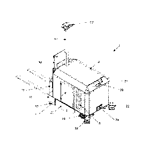
Figure 2 is an exploded view of the AGV lift truck vehicle of the present
invention.
Figure 3 is an exploded view of the components of the chassis constituting the
base of the
AGV lift truck vehicle of the present invention.
Figure 4 is an exploded view of the housing supporting the Banner tower of the
AGV lift
truck vehicle of the present invention.
Figure 5a is an exploded view of the principal components mounted upon the
chassis of
the AGV lift truck vehicle of the present invention.
Figure 5b refers to the fully assembled components of Figure 5a which form the
chassis of
the AGV lift truck vehicle of the present invention.
Figure 6 is a detailed view of the internal reinforcing structure supporting
the housing upon
the base of the chassis of the AGV lift truck vehicle of the present
invention.
Figure 7 is a detailed view of the reinforcing towers supporting the housing
upon the
surface of the chassis of the AGV lift truck vehicle of the present invention.
Figure 8a is an exploded view of the lifting system of the AGV lift truck
vehicle of the
present invention.
Date Recue/Date Received 2021-08-24
6
Figure 8b is an exploded view of the fork hanger mechanism and lifting
carriage forming
the lifting system of the AGV lift truck vehicle of the present invention.
Figure 8c refers to the fully assembled components shown in Figure 8b to form
the lifting
system of the AGV lift truck vehicle of the present invention.
Figure 9 is a side view of the means of displacement of the lifting carriage
and fork hanger
of the AGV lift truck vehicle of the present invention.
Figure 10a is a perspective view of the Banner tower of the AGV lift truck
vehicle of the
present invention.
Figure 10b is a front view of the Banner tower of the AGV lift truck vehicle
of the present
invention.
Figure 11 a is a perspective view of the battery box of the AGV lift truck
vehicle of the
present invention.
.. Figure 11 b is an underneath view of the battery box of the AGV lift truck
vehicle of the
present invention.
Figure 12 is an exploded view of the battery box of the AGV lift truck vehicle
of the present
invention.
Figure 13 is a side view of the AGV lift truck vehicle of the present
invention connected to
a charging point.
Figure 14 is a close up view of the charging contact port of the AGV lift
truck vehicle of the
present invention.
Date Recue/Date Received 2021-08-24
7
Figure 15 is an underneath view of the first and second contact points of the
charging
contact port of the AGV lift truck vehicle of the present invention.
Figure 16 is a front perspective view of the self-charging port of the AGV
lift truck vehicle
of the present invention.
Figure 17 is a diagram of the user interface of the AGV lift truck vehicle of
the present
invention.
Figure 18 is a front view of the manual remote control of the AGV lift truck
vehicle of the
present invention.
DESCRIPTION OF THE PREFERRED EMBODIMENTS
In the first place, it must be clearly understood that similar reference
numbers are utilised
to identify the same structural elements, sections, or surfaces in a
consistent manner in
the various drawings, by virtue of the fact that such elements, sections, or
surfaces can be
explained or described in greater depth in the complete written specification
whereof this
detailed description is an integral part.
The embodiments described in the present document comprise a combination of
advantages and characteristics destined to overcome diverse deficiencies
associated with
certain previous devices, systems, and methods. The aforestated has delineated
in a
broader manner the technical characteristics and advantages of the embodiments
divulged
in order that the following detailed description may be better understood. The
different
characteristics and advantages described previously, together with others,
shall be evident
to those skilled in the art once having read the detailed description and
through the
consultation of the appended figures. It must be appreciated that the
conception and the
specific embodiments divulged may be readily utilised as a basis to modify or
design other
devices or vehicles in order to achieve the same ends as the embodiments
divulged. It
Date Recue/Date Received 2021-08-24
8
must also be understood that such equivalent devices or vehicles do not
diverge from the
spirit and scope of the principles divulged in this document.
The present divulgement refers to a design of an automatically guided vehicle
belonging to
the AGV (automatic guided vehicle) type, in particular the present divulgement
relates to
an automatically guided electric lift truck vehicle presenting the ability to
move products
from a point "A" to a point "B" together with being compliant with the safety
standard
ANSI/ISTDF B56.5 for industrial autonomous vehicles.
It is equipped with an automatic battery charging system of as and when
required type to
reduce the involvement of personnel in the operation of the vehicle, and it
presents a
comprehensive safety system enabling it to stop the vehicle upon detection of
a fault in the
various systems constituting the operation of the vehicle; within this safety
system there is
included the detection of objects or persons obstructing the passage of the
vehicle
together with emergency stops located at different points of the vehicle,
audible alarm and
visual alarms, such that the vehicle may interact with the personnel of the
plant and/or
warehouse.
More than one unit of this same vehicle may operate in the same warehouse
and/or
production line by virtue of the fact that it has the capacity of being able
to work under a
control regulating the movement and operations of these vehicles.
For the purposes of the display of alarm messages, state of the tasks, and
calibration, the
lift truck vehicle of the present invention presents a user interface
comprising a touch
screen located upon the casing of the vehicle.
In relation to the drawings, and more particularly to Figures la, 1 b, 1 c and
id, there is
provided a general view of the automatic guided vehicle (1) presented fully
assembled.
Within the principal components of the present invention there is an automatic
lift truck
vehicle having as principal components a very robust metal chassis (described
below)
covered by a protective casing (2) of compact design permitting it to move
freely through
narrow corridors or passages within the warehouses or plants. The protective
casing (2)
Date Recue/Date Received 2021-08-24
9
has two side doors (3, 4), one in each side wall of the casing (2), for the
purpose of
connecting the power board (28) and the control board (27), respectively.
Furthermore, there is a louvre type hatch (5, 6) upon the sides of the
protective casing (2),
immediately behind the respective side doors (3, 4), for the purpose of
introducing or
withdrawing the battery box (26), shown in Figure 2. The louvre type hatches
(5, 6) permit
dissipation of the heat emitted within the casing and, differing from the side
doors (3, 4),
which have a simple opening system, these may only be removed when the
perimetrical
safety bolts securing them are removed.
The front part of the chassis constituting the lift truck vehicle (1) presents
a compartment
(7) formed by two plates and a cold rolled frame of sufficient strength for
the purpose of
the attachment of the Banner tower (8), this in turn having attached at the
free extremity
thereof a base (92) for the purpose of the attachment of the navigation
sensor. The
compartment (7) is sufficiently strong to support the Banner tower, having all
the
accessories thereof installed, and to resist an impact by the mast (10),
should this latter
give way before the weight of a given load or through a collision.
With reference to the mast (10), it is supported upon a reinforced base (11)
resting upon
the plate of the chassis (described in Figure 5a). The reinforced base (11),
in turn, is
supported upon the ground by means of two sets of fixed double wheels (12)
contributing
to the displacement of the lift truck vehicle. The mast (10) furthermore
serves as support
and guide for the lifting carriage (13), the fork hanger frame (15) and the
forks (16), whilst
a lifting cylinder (14) is positioned upon the support plate (68) constituting
the mast (10).
One driving and steered wheel (17) is coupled to an electric motor (18) in
order to displace
and steer the lift truck vehicle. The wheel (17) and electric motor (18)
assembly is
strategically located in a central position under the chassis of the lift
truck vehicle, given
that by positioning the motor in the centre there is a shorter distance
between the battery
box and the electric motor and, furthermore, as this position achieve the
placement of
more weight upon the rear wheels, more traction and control is generated when
braking. A
greater weight upon the rear wheels also assists in acceleration upon slippery
surfaces,
Date Recue/Date Received 2021-08-24
10
provides greater support for the brakes and contributes to preventing the
front part of the
lift truck rising when a given weight is being loaded.
A further benefit from the location of the electric motor is the space
rendered available
upon the chassis covered by the casing by virtue of the fact that it leaves
space free for
the implementation of other accessories, such as power board, the control
board, the
battery box, the counterweight, the casing reinforcement frame, etc. In fact,
by placing
more weight upon the rear part of the lift truck vehicle, the rear wheels can
absorb the
force resulting from frontal impacts with greater facility.
The rear wheels (19), differing from the front wheels (22), present free
movement and are
located at the rear extremity of the chassis of the lift truck vehicle (1),
permitting them to
move in the direction of the driving and steered wheel (17) by virtue of the
fact that they
orient in the direction of this latter when the vehicle moves in a straight
line or they rotate
in the corresponding sense when the vehicle is turning.
A flanking cover (20) encloses three quarters of the length of the chassis of
the lift truck
vehicle (1) in order to prevent the introduction of objects beneath the same
which may
obstruct the driving wheel (17) during the displacement of the vehicle.
Displacement of the lift truck vehicle of the present invention is guided
automatically by
means of routes programmed for the movement of goods within warehouses and
production lines; for this purpose the lift truck vehicle described makes use
of navigation
sensors (21) and safety devices, such as safety laser scanners (22), which in
conjunction
with references installed in the warehouses or production lines comply with
the industrial
and machinery safety regulations of the country wherein they are marketed, by
virtue of
the high degree of interaction thereof with the personnel of the warehouses or
production
line.
An additional safety accessory is an angular position sensor (23) mounted upon
a
machined part (24) at each extremity of the piston support beam (13a). By
means of the
assistance of the angular position sensor (23) the rear part of the lift truck
(1) can be
Date Recue/Date Received 2021-08-24
11
prevented from raising when it is supporting a given load, this representing
the greatest
number of accidents through the use of lift trucks in the present day. The
angular position
sensor (23) measures the inclination of the lift truck recorded during the
manoeuvre in
order to determine whether it lies within a preestablished safety range such
that, should
.. the range of inclination be exceeded, an acoustic and visual warning signal
will be emitted,
notifying the error and stopping the movement of the lifting carriage (13).
In the lower part of the rear part of the casing (2) there is the self-
charging port (2a) for
feeding the batteries (not shown) located within the battery box (26). Upon
the casing (2)
there is also located the female connector (2b) for connecting the manual
remote control
(not shown) together with an emergency stop button (2c). In Figure la there is
clearly
shown the navigation sensor (21), the strobe light (54) and a Moxa access
point (55a)
these being located in the upper part of the Banner tower (8).
.. In Figure 2 there is provided an exploded view of the lift truck vehicle
(1) of the present
invention wherein there is a cold rolled base plate (25) whereupon there is
placed the
compartment (7) which, in turn, serves as support for the Banner tower located
upon the
perimetrical frame (43) thereof.
As mentioned in foregoing paragraphs, a casing (2) covers in a removable
manner the
total length of the base plate (25), from the rear extremity thereof as far as
the internal face
of the compartment (7) having the purpose of protecting the internal
components of the
proposed lift truck vehicle (1). At the opposite extremity from the
compartment (7), upon
the base plate, there is located the battery box (26) which, in the preferred
embodiment,
has wheels such that it may be easily installed or withdrawn through the
louvre type
hatches (5, 6) of the casing (2). The battery box stores the electrical energy
required for
the operation of the driving wheel (17), of the user interface (30), and of
all the electrical
devices of the lift truck vehicle. For their part, the side doors (3, 4) give
access to the
power board (28) and to the control board (27), respectively.
As may be observed in Figure 2, a counterweight (29), constituted by a series
of metal
plates joined to one another, is located at the rear extremity of the base
plate (25),
Date Recue/Date Received 2021-08-24
12
immediately behind the battery box (26), for the purpose of counteracting the
weight of the
load lifted. Furthermore, there is a reinforcing skeleton (31) formed from box
section RHS
tubes in order to support the weight of the casing (2) and prevent the
internal components
from being damaged should an object fall thereupon.
With respect to the user interface (30), the user views it by means of an
aperture in the
casing (2), however it is maintained supported upon a plate welded upon the
reinforcing
skeleton (31) by means of a frame (32), having the objective that the lift
truck vehicle (1)
may be utilised without the casing (2) should there be a requirement for
maintenance to
the internal components thereof or repair activities.
As illustrated in Figure 3, the base plate (25) constituting part of the
chassis is joined to a
reinforcing structure (33) formed by joining "I" type beams, by virtue of the
fact that they
permit flexibility and support the entire structure. The base plate (25) is
constituted by a
cold rolled plate presenting a rectangular cut-out (34) in the front extremity
thereof having
the purpose of attaching a support plate of the reinforced base (11)
(described below). A
central circular opening (34a) permits the passage of the electric motor
coupled to the
driving and steered wheel (17). Once the base plate (25) has been joined to
the reinforcing
structure (33) a second blocking front plate (35) is welded in a perpendicular
manner to the
rectangular cut-out (34) of the base plate (25), between the two longitudinal
beams (36)
and parallel to the joining beam (37) constituting the reinforcing structure
(33).
Upon the rear extremity of the longitudinal beams (36) there is furthermore a
second
structure of "I" beams formed by two short longitudinal beams (30) joined by
means of two
internal beams (39) constituting a frame for the attachment of two support
plates (40) for
the installation of the free wheels (19), and two angled frames (41) for the
installation of
the safety laser scanners (22).
As has been described in foregoing paragraphs, the compartment (7) is a
reinforced
component by virtue of the fact that it is located at the front extremity of
the lift truck (1) at
a point close to the lifting device, it consequently being constituted by two
cold rolled
plates (42) joined by means of a perimetrical central frame (43) which, in
turn, is reinforced
Date Recue/Date Received 2021-08-24
13
by internal parallel plates (44), this providing greater strength to the
structure of the
compartment (7) and permitting attachment of the Banner tower (8) upon the
very frame
thereof (43), as shown in Figure 4.
.. In Figures 5a and 5b there is shown the internal reinforcing structure (45)
supporting the
compartment (7) upon the front extremity of the base plate (25). The internal
reinforcing
structure (45) in addition to supporting the compartment (7) safely maintains
the power
board (28) upon the base plate (25) by means of the attachment bar (46).
Returning to the
base plate (25), upon the longitudinal beams (36) of the reinforcing structure
(33) there is
.. inserted the reinforced base (11) constituted by a horizontal plate (48)
and three
perpendicular plates (49) at each extremity, which same, in turn, are spaced
one from
another in order to form two housings (upon each side) for the installation of
the two sets
of double wheels (12) supporting the front structure of the lift truck vehicle
(1). These
wheels, differing from the rear free wheels (19), are fixed by virtue of the
fact that they
support the entire weight of the load supported upon the forks, such that the
axis of
rotation thereof is parallel to the load axis of the lifting device.
Furthermore, the side plates
(49) cover the entirety of the upper, front and rear extremities of the fixed
wheels (12) in
order to prevent objects being introduced which might obstruct them during the
advance of
the lift truck vehicle (1).
In terms of the horizontal plate (48), this latter is designed to hold the
piston support beam
(13a) whereupon is supported the mast (10) which, in turn, has at each
extremity the
machined parts (24) for the installation of the angular position sensors (23).
In addition to the angular position sensors (23) the lift truck vehicle of the
present invention
utilises a navigation sensor (21) continually calculating by estimation the
position,
orientation and speed (direction and rapidity of movement) of the lift truck
vehicle (1)
without the need for external references, and a proximity sensor (50) mounted
below the
piston support beam (13a) within a safety clamp, for the purpose of detecting
possible
.. objects in front of the lift truck (1). This proximity sensor (50) is an
essential safety tool by
virtue of the fact that on being an automatic vehicle it must be capable of
becoming aware
of the presence of unexpected objects or persons crossing in front of it.
Date Recue/Date Received 2021-08-24
14
Referring to Figure 6, therein may be observed in detail the internal
reinforcing structure
(45) formed from a tubular box frame (51) of RHS having two vertical
longitudinal beams
and at least four horizontal joining tubes. The upper part of the internal
reinforcing
structure (45) presents a duct (52), in the form of a "T", for the passage and
housing of the
connecting cables between the power board (28) and the control board (27) by
means of
trough (53), and within the Banner tower (8) towards the navigation sensor
(21), strobe
light (54), and a Moxa access point (55a) by means of trough (55).
Two short longitudinal beams (56) of box section tubing of RHS material permit
supporting
the internal reinforcing structure (45) of the compartment (7), as shown in
Figure 5b,
leaving a sufficient distance such as to not damage the ducting (52). At the
left extremity of
the upper horizontal tube constituting the internal reinforcing structure (45)
there is located
an extension piece (57) of plate holding the attachment bar (46), by means of
the upper
extremity thereof, which supports the power board (28), for which purpose it
utilises an
upper and lower plate (58, 59) having perforations for the purpose of bolting
onto the
extremities of the power board (28), together with two plates at an angle of
900 (60)
reinforcing such holding. It must be noted that the plates (58, 59) are not
located at the
same level as the extremities of the attachment bar (46), by virtue of the
fact that it
engages by means of the upper extremity thereof in a perforation in the upper
plate (58)
and by means of the lower extremity thereof it passes through the lower plate
(59) such as
to maintain the power board (20) distanced from the upper surface of the base
plate (25),
having the purpose of preventing short circuits or of it becoming wet should
water
penetrate towards the interior of the casing (2). By virtue of the fact that
the power board
(28) is maintained suspended between the plates (58, 59), the free extremity
of the power
board (28) rests upon the support (61), shown in Figure 5a and located upon
the surface
of the base plate (25), in order to stabilise it.
For the purpose of affixing the internal reinforcing structure (45) to the
base plate (25)
there are employed two reinforcing towers (62), shown in Figure 7, formed from
a portion
of box section tubing (63) having at least three support gussets (64) upon the
faces of
each portion of box section tubing (63), permitting them to be firmly seated
upon the
Date Recue/Date Received 2021-08-24
15
surface plate (25). The reinforcing towers (62) stabilise the compartment (7)
by means of
two 900 plates (65) joined to one another by means of a length of plate (65a).
A pair of
struts (66), shown in Figures 5a and 5b, are welded at one extremity to the
compartment
(7) and at the opposite extremity thereof to the base plate (5) in order to
maintain the
compartment firmly joined as an assembly with the reinforcing towers (62) and
the internal
reinforcing structure (45).
Making reference now to Figures 8a, 8b and 8c, therein is shown the lifting
device
comprising a mast (10) formed by two "C" type vertical beams (67) joined by
means of a
support plate (68) serving to attach the mast (10) to the horizontal plate
(48) of the
reinforced base (11) which forms part of the base plate (25) of the lift truck
vehicle (1).
Three plates (69) distributed between the "C" type beams (67) are employed as
reinforcement of the mast (10).
Upon the edge of the vertical beams (67) of the mast (10) there are positioned
safety
supports (70) having a series of perforations (71) for the adjustment thereof
to different
heights upon the edges of the beams (67) by means of bolts. Two hooks (71) at
the lower
extremity of the safety supports (70) subject the upper frame (72) of the fork
carriage (15)
should the load supported exceed the limit of strength of the lifting cylinder
(14).
The lifting carriage (13) is constituted by a rectangular frame (73) having
attached upon
each exterior face of the vertical sides thereof (74) two sets of angularly
displaced wheels
(75) facilitating the displacement thereof when it is fitted within the
channels defined by the
two "C" type vertical beams (67) of the mast (10). In this respect, Figure 9
shows the
position of the wheels (75) permitting that the rear wheels (76) run within
the rear part of
the "C" type vertical beams (67) whilst the front wheels (77) run within the
front part of the
"C" type vertical beams (67), consequently stabilising the lifting carriage
(13) within the
mast (10) in order to prevent ruptures which might occur by virtue of
misalignment of the
lifting carriage (13) during the displacement thereof on lifting a given load.
Two sets of
bearings (78) upon each exterior face of the vertical sides (74) contribute to
maintaining
the lifting carriage (13) stabilised during the displacement thereof, the
bearings (78) being
Date Recue/Date Received 2021-08-24
16
located in a perpendicular sense with respect to the internal faces of the "C"
type vertical
beams (67).
To complete the lifting device there is configured a fork hanger frame (15)
constituted on
the basis of a rectangular plate frame having two vertical plates (79) joined
at the lower
extremity thereof by a horizontal perpendicular plate (80) and two horizontal
perpendicular
plates (81) of treated steel. A pair of internal vertical plates (82)
reinforce the horizontal
plates (81) by virtue of the fact that the each of the latter support two
attachment plates
(83) welded to the internal faces of the vertical sides (74) forming the
lifting carriage (13).
A front plate (84) of treated steel is welded to the plates (79) upon each
plate (82) to
support the forks (16) of the lift truck upon a pair of notches (85) formed in
the front plate
(84) by means of two extremities in hook form (86) in the load backrest (16a)
of the forks
(16). Furthermore, in the lower part of the load backrest (16a) there is
defined an extremity
in hook form (87) which are attached to two pieces (88) of treated steel
welded to the
horizontal perpendicular plate (80) of the fork hanger frame (15).
As aforestated, the safety supports (70) may be adjusted to different heights
upon the
edges of the vertical beams (67) of the mast (10), however, in addition, they
present a
perimetrical flange (88), shown in Figure 8a, assisting in maintaining the set
of wheels (75)
within the vertical beams (67) and serving as a means of retention should they
depart from
the track thereof.
Referring to the lifting cylinder (14), this is located upon the support plate
(68) of the mast
(10) by means of four bolts whilst the thrusting extremity (14a) of the
lifting cylinder (14) is
bolted to the internal face of the horizontal plate (74a) maintaining joined
the vertical sides
(74) of the lifting carriage (13) which, in turn, surrounds the lifting
cylinder (14) when it is
located within the mast (10).
With respect to Figures 10a and 10b, therein is shown the Banner tower (8),
being a
structure of box section tubing of RHS material having within the interior a
series of
reinforcing parts (89) located by means of flood weld in the orifices
presented by the RHS
such as to leave solely the second orifice to affix the upper part thereof.
The series of
Date Recue/Date Received 2021-08-24
17
reinforcing parts (89) covers the join area in contact with the compartment
(7) in order to
strengthen the structure thereof, in such manner that the lower portion of the
Banner tower
(8) is affixed to the wall of the compartment (7) by means of a series of
clamps (90). The
lower portion of the Banner tower (8) presents an orifice (91) which abuts the
trough (55)
defined by the ducting (52), shown in Figure 6, for the passage of the
connecting cables
which run from the control board (27) and from the power board (28) toward the
navigation
sensor (21), the strobe light (54) and the Moxa access point (55a).
For the attachment of the navigation sensor (21), the strobe light (54) and
the Moxa
access point (55a), there is employed a base (92) affixed to the upper
extremity of the
Banner tower (8) by means of two clamps. The base (92) furthermore forms an
access
port between the navigation sensor (21), the strobe light (54) and the Moxa
access point
(55a) and the interior of the Banner tower (8) for the passage of the
connecting cables.
In Figures 11a and 11 b there is shown the battery box, the same being formed
by two side
plates (93) having a cut-out in the lower part (94) and two joining plates
(94) having
handgrips allowing the battery box (26) to be lifted or pulled for the purpose
of introducing
it into or withdrawing it from the casing (2). Furthermore, in order to
facilitate the
displacement thereof, the battery box presents a base (95) having a series of
perimetrical
cut-outs permitting the free passage of the wheels (96) for the displacement
thereof. The
wheels (96) are mounted upon a drive train, shown in Figure 12, permitting
them to
contract within the battery box (26) for the purpose then being held supported
upon a
plurality of seats (97) when it is placed upon the base plate (25) forming the
chassis of the
lift truck vehicle (1). When it is desired to withdraw the battery box (26)
from the casing (2),
-- the two louvre type hatches (5, 6) are removed and the wheels (96), which
exceed the
height of the seats (97), are released for the purpose of being able to move
the battery box
with greater facility.
In conformity with Figure 13, in periods of inactivity or preestablished
charging periods the
automatic guided vehicle (1) travels to a charger (200) located at a site
having coordinates
preestablished in the control logic thereof such that, when the vehicle is in
a state of
inoperativeness, the latter travels and connects in an automatic manner to a
charging
Date Recue/Date Received 2021-08-24
18
contact port (201) of a charger (200) by means of the self-charging port (2a)
thereof with
the charging contact port (201) of the charger (200).
Referring to Figure 14, the charging contact port (201) of the charger (200)
comprises a
pair of contact pistons (201a, 201b) carrying a voltage of 220 V or 440 V, a
current of 250
A and a frequency of 60 Hz towards the self-charging port (2a) of the vehicle
(1), wherein
a first contact member (201a) connects to a first conductive surface (20a) and
a second
contact member (201b) connects to a second conductive surface (20b) of the
self-charging
port (2a). In this manner, the supply voltage provided by the charger (200) is
carried
towards the vehicle (1) in order to charge the bank of batteries thereof (not
shown).
Furthermore, each of the first and second contact members (201a, 201b) of the
charging
contact port (201) of Figure 15 consist of a cylinder (202) of non-conductive
material and a
conductive cap (203) provided at the extremity of each cylinder (202). The
first and second
.. contact members (201a, 201b) are mounted upon a first mechanical head (204)
comprising a housing (205) having elements of mechanical correction such as at
least one
spring providing a backwards or forwards displacement of approximately 10 mm
to the first
and second contact members (201a, 201b) of the charging contact port (201).
Continuing with Figure 15, the first mechanical head (204) is attached to a
second
mechanical head (206) comprising a base housing (207) mounted upon at least
four
cushioning elements (208) providing a forwards or backwards linear movement of
approximately 60 mm to the charging contact port (201) of the charger (200).
With reference to Figure 16, the self-charging port (2a) of the vehicle (1)
consists of a first
conductive surface (20a) and a second conductive surface mounted upon an
element of
non-conductive material housed within a casing (210).
The casing (210) is mechanically affixed by means of at least four sprung
elements (211)
upon a base casing (212). As a consequence thereof an angular mechanical
correction is
achieved upon the first and second conductive surfaces (20a, 20b) at the
moment of
achieving a connection between the first and second contact members (201a,
201b). This
Date Recue/Date Received 2021-08-24
19
is possible by virtue of the movement realised in the centre of affixation
thereof providing
degrees of rotational freedom opposed with sprung elements (211) which absorb
the
forces that the contact members of the charger exert upon the conductive
surfaces (20a,
20b) of the self-charging port (2a) of the vehicle (1).
5
In such manner, and in conformity with Figure 14, certain freedom is achieved
in the
electrical connection of the self-charging port (2a) of the vehicle (1) with
respect to the
charging contact port (201) of the charger (200). Consequently, it is not
necessary that the
automatic guided vehicle (1) be required to be positioned at an exact point in
relation to
10 the charger for the recharging of its bank of batteries.
In conformity with Figure 17, the automatic guided vehicle (1) comprises a
user interface
(30) displaying a graphical interface by means whereof there are established
parameters
of control and function of the vehicle established previously in the control
logic of a
programmable logic controller (300). According to the preferred embodiment of
the
invention, the user interface is a touch screen.
In a constant manner and in real time a navigation sensor (21) sends signals
to the PLC
(300) containing information data in relation to the position of the vehicle,
whilst the Moxa
access point (55a) receives from and sends to the PLC (300) information
signals with
respect to the data of tasks and programmed routes which the vehicle (1) must
execute.
As a consequence, the PLC processes the information and in conformity with the
tasks
established sends the corresponding control signals to at least one electric
motor (18) to
displace and direct the vehicle toward the location established. Furthermore,
based upon
the information data of the task, the controller determines the moment in
relation to the
operation of the lift truck of the vehicle (1) by means of control signals
sent to a hydraulic
pump which activates/deactivates the lifting cylinder of the front lifting
system of the
vehicle (1).
In addition, for the purpose of preventing collisions the automatic guided
vehicle (1)
possesses a safety system comprising three safety scanners (22) whereof two
thereof are
each one located at each front corner of the vehicle (1), each safety scanner
(22)
Date Recue/Date Received 2021-08-24
20
establishing a safety range of 4 metres together with a warning zone of 15
metres and
offering detection through 270 degrees to detect bodies coming within range.
In this
manner the PLC (300) obtains the information recorded by the scanners (300)
for the
processing thereof. In this manner, by means of the information, the control
logic of the
vehicle, through processing together with the PLC, determines a precise
trajectory
preventing collisions or impacts with other bodies in conformity with the
preestablished
route.
Furthermore, an inductive proximity sensor (302) is connected to the PLC
(300), as is an
audible alarm (303) which activates the PLC should the safety system detect an
obstacle
during the trajectory of the vehicle (1). The activation of a Banner tower (8)
is controlled by
means of the PLC (300) during the functioning of the vehicle (1) providing a
highly visible
indication to notify the state of the operations of the vehicle. The angular
position sensor
(23) measures the inclination of the lift truck recorded during the manoeuvre
such manner
that the values measured are sent to the PLC (300) which processes the
information in
order to determine whether the values measured are maintained within a safety
range
preestablished in the control logic of the vehicle.
At least one safety encoder (304) provides information signals to the PLC
(300) regarding
the position, the angle and the revolutions in specific angular increments.
Each angular
increment has assigned an unequivocal coat pattern wherein the number of code
patterns
per revolution determines the resolution. Each code pattern constitutes an
unequivocal
reference and, consequently, an absolute position. Furthermore, a linear
encoder (305)
provides the PLC with the direct and continuous measurement of the space
travelled
through and the time of movement of the vehicle. In this manner the PLC,
through the
control logic thereof, realises the corresponding calculations in order to
obtain variables
such as the power and the mechanical work, the force or the speed, for the
control of at
least one electrical steering motor (18) in order to displace and direct the
vehicle (1)
towards the location established.
Date Recue/Date Received 2021-08-24
21
Continuing with Figure 17, a first switch (306) activates the operation of the
user interface
(30) whilst a second switch (307) activates the operation of the navigation
sensor (21), the
Moxa access point (55a) together with the safety scanners (22).
Furthermore, a modular input output system (308) serves as means of electrical
connection between the PLC (300) and the control relays of the at least one
electric motor
(8) and a relief valve (309).
Referring to Figure 18, which shows the manual remote control (400) comprising
an
electrical control board (not shown) housed within a control casing (401). The
board
comprises: a first pressure switch (402) commanding the increase in speed of
the vehicle,
a second pressure switch (403) commanding the reduction in speed of the
vehicle, a first
control lever (404) commanding the direction (left and right) of the vehicle
together with the
raising or lowering of the forks of the lift truck, a second control lever
(405) commands the
forwards or backwards movement of the vehicle together with the upward or
downward tilt
of the forks of the lift truck, an emergency stop button (406) deactivates the
operation of
the vehicle, and a bypass switch (410) activates/deactivates the safety
systems of the
vehicle.
Furthermore, a first indicator element (407) informs the user in a visual
manner regarding
the state of the forks of the lift truck, a second indicator element (408)
informs the user in a
visual manner regarding the state of the safety systems of the vehicle, and a
third indicator
element (409) informs in a visual manner the state of operation of the manual
mode of the
vehicle. Additionally, the control (400) comprises a cable whereof one of the
extremities
thereof is connected to the electronic control board and the opposite
extremity comprises a
male connector (not shown) which couples to the female connector (2b) of the
vehicle (1)
in conformity with Figure la.
Although preferred embodiments have been shown and described, a person skilled
in the
art will be capable of modifying the same without departing from the scope or
from the
teachings of the present document. The embodiments described herein are solely
examples and are not !imitative.
Date Recue/Date Received 2021-08-24
22
Variations and modifications of the system are also possible, eliminating one
or other of
the processes described or adding a function to the system. All these
variations lie within
the scope of the invention.
For example, the navigation and safety devices, the type of materials utilised
and the
location of the equipments, such as the power board, the control board and the
battery
box, together with the doors and the devices located upon the Banner tower,
and the
control and safety equipments may be altered without the dimensions and
configuration
thereof being of importance. Consequently, the scope of protection is not
limited to the
embodiments described in the present document, it been solely limited by the
claims which
follow, the scope whereof shall include all the equivalents of the matter
object of the
claims.
Date Recue/Date Received 2021-08-24