Note: Descriptions are shown in the official language in which they were submitted.
CA 03135288 2021-09-28
WO 2020/205215 PCT/US2020/022922
-1-
SELF-CONTAINED CALIBRATION APPARATUS FOR GAS SENSOR
BACKGROUND
[0001] The process industry often employs gas sensors in order to detect
the presence of a
particular gas, often as part of a safety system. This is important as many
gases may be harmful
to human health and/or the environment. Industrial gas sensors are normally
mounted near the
process area of a plant or control room, or an area to be protected.
Generally, industrial gas sensors
are installed at fixed locations and to communicate with monitoring systems.
SUMMARY
[0002] A detachable filter assembly includes a filter, a filter assembly
housing defining a body
of the filter assembly, an attachment mechanism configured to couple to a
sensor installation, a
securing mechanism configured to mate with a mating feature on the sensor
installation, and a
calibration port configured to provide a direct fluid pathway to the sensor
installation.
BRIEF DESCRIPTION OF THE DRAWINGS
[0003] FIG. 1 is a partial cutaway view showing one example of a sensor
module installation.
[0004] FIG. 2 is a perspective view showing one example of a filter
assembly.
[0005] FIG. 3 is a perspective view showing one example of a filter
assembly installation.
[0006] FIG. 4 is a partial cutaway view showing one example of a filter
assembly installation.
[0007] FIG. 5 is a partial cutaway view showing one example of a sensor
module installation.
[0008] FIG. 6 is a bottom view showing one example of a filter assembly.
[0009] FIG. 7 is a perspective view showing one example of a filter
assembly.
[0010] FIG. 8 is a perspective view showing one example of a filter
assembly installation.
[0011] FIG. 9 is a perspective view showing one example of a filter
assembly.
[0012] FIG. 10 is a bottom view showing one example of a filter assembly.
[0013] FIG. 11 is a perspective view showing one example of a filter
assembly.
[0014] FIG. 12 is a bottom view showing one example of a filter assembly.
[0015] FIG. 13 is a perspective view showing one example of a sensor module
installation.
[0016] FIG. 14 is a perspective view showing one example of a sensor module
installation.
[0017] FIG. 15 is a simplified block diagram showing one example of a
sensor module
installation.
[0018] FIG. 16 is a flow diagram showing one example operation of providing
calibration fluid
to a sensor.
CA 03135288 2021-09-28
WO 2020/205215 PCT/US2020/022922
-2-
DETAILED DESCRIPTION
[0019]
Gas detectors are often deployed in industrial environments. These gas
detectors may
be configured to detect the presence of various gases including combustible,
toxic, flammable
gases, and/or oxygen depletion in the environment. These gas detectors are
often placed in a fixed
location that can be difficult to access. Sometimes the environments in those
locations can be
hazardous. For example, they may contain combustible, toxic, or flammable
gases and liquids.
[0020]
The sensors typically employed within gas detectors need to be calibrated with
target
gas and clean air during installation. These sensors will often deteriorate
and lose calibration over
the sensor's service life or they can become contaminated after an extended
period of operating in
an environment that is polluted from contaminants such as dust or debris. This
will dull the
sensitivity of the sensor and its ability to pick up smaller traces of gases.
[0021]
Calibration is needed to ensure that the analog, digital, and discrete outputs
of the
sensor are all accurately transmitting the target gas concentration detected
by the sensor.
Calibration correctly zeroes the sensor to ideal air conditions. Once zeroed,
the target gas must be
connected to the sensor to induce a point of reference for detection. However,
these sensors are
often located in inconvenient locations within industrial environments thereby
making it difficult
to calibrate or otherwise maintain the sensor. These locations can be
difficult to reach or access
and may contain dangerous densities of combustible, toxic or flammable gases,
or may otherwise
be deplete of oxygen. Therefore, calibration with current systems can be time
consuming and
expose workers to dangerous conditions.
[0022]
Filters are typically employed within the gas detectors. These filters are
meant to
protect the sensors from contamination from dust or debris while still
allowing the sensor to access
target gases. This is meant to reduce the needed maintenance on the sensor
during its service
lifetime. However, these filters can become clogged or otherwise deteriorate
over time which
reduces the sensor's accessibility to target gases and need to be maintained
or replaced. As well as
being located in inconvenient or hazardous locations, current systems often
require a lengthy
disassembly of a gas detector installation in order to replace or maintain
these filters. This increases
the cost of service as well as a worker's exposure to hazardous conditions.
[0023]
A gas detector system that will reduce the burden, danger and expense
associated with
sensor maintenance while still allowing for accurate measurements is needed.
One such system,
provided herein, includes a self-contained calibration apparatus. The
calibration apparatus
CA 03135288 2021-09-28
WO 2020/205215 PCT/US2020/022922
-3-
comprises a filter assembly that includes a housing, a calibration port and
attachment and securing
mechanisms as a separate and removable assembly from a sensor installation.
This design allows
for quicker and easier replacement and maintenance of the sensor and filter
within the gas detector.
The calibration port allows for fixed gas calibration to be performed by a
user on various
installations thereby reducing the cost and burden of calibration in hazardous
and inconvenient
locations.
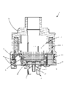
[0024] FIG. 1 is a partial cutaway view showing one example of a sensor
module installation.
Sensor module installation 10 includes sensor module 12, sensor module housing
14, sensor
module housing cover 16, filter assembly 18, filter assembly housing 20,
filter 22, calibration port
24, attachment mechanisms 26, securing mechanisms 28, sensing element 30,
electronics 32,
threads 34, gasket 36, and coupling mechanisms 38.
[0025] Sensor module 12 contains sensing element 30 and electronics 32.
Sensing element 30
can be any number of process analytics sensors used in process environments
but is illustratively
shown as a gas sensor. Sensing element 30 is electrically coupled to
electronics 32. Electronics
32 can contain any number of components, including, but not limited to,
processors, measurement
circuitry, communication circuitry, and/or controllers. For example, in one
embodiment,
electronics 32 could include measurement circuitry configured to receive a
signal from sensing
element 30, a processor configured to calculate a sensor-related output,
communication logic
configured to generate a signal indicative of the sensor-related output, and
communicate wirelessly
via a transmitter, or through a wired loop, to a display panel or a user
interface (such as a computer
in a control room). Electronics 32 could include a controller configured to
generate a control signal
to have sensor installation 10 preform a function based on the sensor-related
output or have some
other aspect of a process control system perform a function based on the
sensor-related output, like
the output of an alarm or notification, or the adjustment of a valve, for
example.
[0026] Sensor module 12 is contained within sensor module housing 14 and
sensor module
housing cover 16. Cover 16 is placed over module 12 and couples to housing 14
by threads 34.
Threads 34 are on a surface of housing 14 and a surface of cover 16. While
threads are
illustratively shown, any number of suitable coupling techniques, or
combination thereof, could
be used, including, but not limited to, press fit, keying features, latches,
barbs, other mating
features, etc. Housing 14 and cover 16 provide protection to elements within,
such as sensing
element 30 and electronics 32. Housing 14 and cover 16 could also provide
compliance with
CA 03135288 2021-09-28
WO 2020/205215 PCT/US2020/022922
-4-
hazardous locations standards by forming flame-proof pathways and seals meant
to prevent the
flow and escape of fluids from the sensor module installation. Sensor module
installation 10 could
be made from any number of suitable materials, but particularly those suited
for compliance with
hazardous location standards. Particularly, but not limited to, non-ferrous
metals containing high
thermal conductivity like copper-aluminum alloys, stainless steel, silver,
aluminum and galvanized
steel, for example, or non-metallic, non-sparking materials like plastics,
woods, and thermoplastic
polymers. Such materials are known and commonly used in the manufacture of gas
sensor
installation and non-sparking and explosion-proof equipment.
[0027] Filter assembly 18 is a field-replaceable, separable and removable
component of
installation 10. Filter assembly 18 preferably includes a filter assembly
housing 20, filter 22 and
gasket 36. Filter assembly housing 20, which includes attachment mechanisms 26
and securing
mechanisms 28, is configured to prevent contaminants such as debris and dust
from reaching filter
22 and sensing element 30. Filter 22 and gasket 36 are configured to prevent
contaminants such
as debris and dust from reaching sensing element 30 and an interior of sensor
installation 10. In
one embodiment, filter 22 and gasket 36 are configured to provide compliance
with safety-related
standards (e.g. Ingress Protection Rating 66 "IP66" or Ingress Protection
Rating 67 "IP67"). In
another embodiment, filter 22 and gasket 36 are configured to provide
compliance with safety-
related standards (e.g. National Electrical Manufactures Association Standards
"NEMA").
[0028] Attachment mechanisms 26 and securing mechanisms 28 allow for a tool-
less coupling
of filter assembly 18 to installation 10. While embodiments are generally
described where the
attachment mechanism and securing mechanism are separate, it is expressly
contemplated that
embodiments can be practiced where a single integrated member accomplishes
both functions. For
example, upon applying an insertion force, attachment mechanisms 26 and
securing mechanisms
28 may couple to a receiving portion of installation 10, thereby securing
filter assembly 18 to
installation 10 without requiring any tools. Filter assembly 18 may then be
removed by hand from
installation 10 by compressing attachment mechanisms 26 and securing
mechanisms 28 and
pulling filter assembly 18 away from installation 10. Attachment mechanisms 26
are shown as an
inverted "U" shaped body but could be any suitable shape to allow for tool-
less coupling and
removal. Securing mechanisms 28 are shown as latching features with a
mating/receiving pair in
installation 10 but could be any suitable feature for securing filter assembly
18 to installation 10
such as, but not limited to, inserts, barbs, etc. Filter assembly 18 could
also include an alignment
CA 03135288 2021-09-28
WO 2020/205215 PCT/US2020/022922
-5-
feature such that alignment mechanisms 26 and securing mechanisms 28 have a
single proper
orientation (a single rotatable orientation). This alignment feature could be,
but is not limited to, a
keying feature on a surface of filter assembly 18 with a mating feature on a
surface of installation
10.
[0029] In one embodiment, upon coupling filter assembly 18 to installation
10, filter 22 and
gasket 36 become compressed, creating a seal between filter assembly 18 and
installation 10. In
one embodiment, this compression provides a safety-rated seal (e.g. IP66, IP67
or NEMA) while
still allowing sensing element 30 to be responsive in accordance with known
industry standards.
Filter 22 may comprise a permeable material configured to allow for passage of
certain fluids while
protecting sensing element 30. Filter 22 may also comprise a hydrophobic,
permeable material
designed to protect sensing element 30 from splashing and spraying liquids and
from dust and
other debris that may inhibit performance of sensing element 30. Filter 22 is,
in one embodiment,
configured to protect sensing element 30 from moisture and contaminants such
as debris and dust
in accordance with an Ingress Protection (IP) standard. In another embodiment,
Filter 22 is
configured to protect sensing element 20 from moisture and contaminants such
as debris and dust
in accordance with NEMA standards. As mentioned above, filter 22 may become
clogged or
otherwise degraded and require maintenance or replacement. Filter assembly 18
allows for less
burdensome installation, maintenance and replacement of filter 22 by, for
example, tool-less
coupling and removal of filter assembly 18.
[0030] Filter assembly also includes calibration port 24 and coupling
mechanisms 38.
Calibration port 24 is built-in to filter assembly 18 and provides a fluid
flow passageway with
direct flow access to sensing element 30. Calibration port 24 allows a
calibration hose to be
permanently installed on installation 10. The calibration hose is secured on
calibration port 24 by
coupling mechanisms 38. Coupling mechanisms 38 are illustratively shown as
barbs, but could
also comprise other suitable techniques for securing the calibration hose to
calibration port 24,
including latches, hooks, mating pairs such as keying features, threads,
inserts, etc.
[0031] FIG. 2 is a perspective view showing one example of a filter
assembly. Filter assembly
18 includes filter assembly housing 20, calibration port 24, attachment
mechanisms 26, securing
mechanisms 28, coupling mechanisms 38 and calibration hose 40. Calibration
hose 40 is secured
to calibration port 24 by coupling mechanisms 38. This allows calibration
fluids to flow directly
from calibration hose 40 into calibration port 24 through a fluid flow
passageway with direct flow
CA 03135288 2021-09-28
WO 2020/205215 PCT/US2020/022922
-6-
access to sensor element 30. Filter assembly 18 allows for a fixed and
permanent installation of a
calibration fluid mechanism (e.g. calibration hose 40) such that calibration
can be done with less
burden, danger, and expense, particularly when a sensor installation (e.g.
installation 10) is in a
difficult to access or hazardous location by utilizing calibration hose 40 to
feed calibration fluid to
sensing element 30. Calibration hose 40 can be of any length desired to allow
a user to calibrate
sensor installation 10 from a safe or easy to access location. Additionally,
calibration hose 40,
while secured to calibration port 24 by coupling mechanisms 38, can still be
removed by a user so
that removal of or change of location for installation 10 can be achieved.
While calibration hose
40 is illustratively shown as a hose, it could also comprise a pipe, a tube,
or any other suitable
technique for providing calibration fluids to filter assembly 18. Calibration
hose 40 could
comprise metal, rubber, polymer, or any other suitable material for
transporting calibration fluids.
[0032] FIG. 3 is a perspective view showing one example of a filter
assembly installation.
Filter assembly installation 42 includes sensor module housing cover 16,
filter assembly 18, filter
assembly housing 20, calibration port 24, attachment mechanisms 26, securing
mechanisms 28,
threads 34, and coupling mechanisms. Lines 44 are included to indicate a
travel direction for filter
assembly 18 as it is coupled to sensor module housing cover 16. A user may
apply an inserting
force, compressing attachment mechanisms 26, while moving filter assembly 18
towards cover 16.
As filter assembly 18 is fit into cover 16 a user may receive an audible or
otherwise sensory
confirmation that securing mechanisms 28 have been properly secured or
otherwise received by
features within cover 16. To remove filter assembly 18 from cover 16 a user
may apply a removal
force, compressing attachment mechanisms 26, and pulling filter assembly 18
away from cover
16.
[0033] FIG. 4 is a partial cutaway view showing one example of a filter
assembly installation.
Filter assembly installation 42 includes sensor module housing cover 16,
filter assembly 18, filter
assembly housing 20, attachment mechanisms 26, securing mechanisms 28, threads
34 and
receiving portion 46. When a user couples filter assembly 18 to cover 16
securing mechanisms 28
are received by receiving portion 46 of cover 16 thereby securing filter
assembly 18 to cover 16.
This creates a sealed, air tight connection between filter assembly 18 and
cover 16. Such a
connection allows installation 42 to be in compliance with safety standards
for process
environments and hazardous locations.
CA 03135288 2021-09-28
WO 2020/205215 PCT/US2020/022922
-7-
[0034] FIG. 5 is a partial cutaway view showing one example of a sensor
module installation.
Sensor module installation 10 includes sensor module housing 14, sensor module
housing cover
16, filter assembly 18, filter 22, calibration port 24, sensing element 30,
gasket 36, and calibration
fluid flow pathway 48 (indicated by an arrow). When filter assembly 18 is
coupled to installation
calibration port 24 provides for direct fluid flow via calibration fluid flow
pathway 48 to sensing
element 30 through filter 22. This is termed "direct fluid flow" even though
the fluid flow passes
through a filter. Calibration fluid flow comes into installation 10 from an
outside source via a
connection (e.g. calibration hose 40) where it can be detected by sensing
element 30. This fluid
flow can be used by sensing element 30 for calibration. Compression of gasket
36 by the coupling
of filter assembly 18 and cover 16 ensures a sealable coupling between filter
assembly 18 and
installation 10.
[0035] FIG. 6 is a bottom view showing one example of a filter assembly.
Filter assembly 18
includes filter assembly housing 20, calibration port 24, attachment
mechanisms 26, securing
mechanisms 28, port attachments 50, and open sensor detection areas 52. As
shown, calibration
port 24 can be coupled to assembly housing 20 via port attachments 50. Port
attachments 50 may
be molded as one continuous piece with calibration port 24 and the rest of
filter assembly 18, or it
may be a separate component otherwise coupled to calibration port 24 and
housing 20 by suitable
coupling techniques including, but not limited to, soldering, welding,
chemical adhesion, chemical
bonding, etc. As can be seen, filter assembly 18 allows for a permanent and
fixed calibration port
(e.g. port 40) while taking very little surface away from a sensor (e.g.
sensing element 30). Port
attachments 50 allow for secure coupling of calibration port 24 to housing 20
while still allowing
open sensor detection areas 52 such that a sensor (e.g. sensing element 30)
can still access process
fluid for detecting process flow characteristics. This shows how a calibration
hose (e.g. calibration
hose 40) can be permanently secured for calibration while still allowing for
the desired sensing.
In one embodiment, a calibration hose is permanently secured to the filter
assembly during the life
of the sensor installation without affecting the operability of the sensing
element which can access
process fluids via the open sensor detection areas.
[0036] FIG. 7 is a perspective view showing one example of a filter
assembly. Filter assembly
60 includes threads 62. Filter assembly 60 is similar to filter assembly 18
except that assembly 60
is threadably coupled to a sensor module installation (e.g. installation 10).
Filter assembly 60 is
coupled to a sensor module installation (e.g. installation 10) via threads 62.
This embodiment still
CA 03135288 2021-09-28
WO 2020/205215 PCT/US2020/022922
-8-
allows for removal of a filter assembly for maintenance and replacement of a
filter while increasing
the resistance of the coupling between a filter assembly and a sensor module
installation to outside
forces such as vibrations.
[0037] FIG. 8 is a perspective view showing one example of a filter
assembly installation.
Filter assembly installation 70 includes filter assembly 72, attachment
mechanism 74, and threads
76. Filter assembly 72 is removably coupled to attachment mechanism 74.
Attachment
mechanism includes threads 76 to secure attachment mechanism 74 to a sensor
module housing
installation (e.g. installation 10). This embodiment still allows for removal
of a filter assembly for
maintenance and replacement of a filter while increasing the resistance of the
coupling between a
filter assembly and a sensor module installation to outside forces such as
vibrations.
[0038] FIG. 9 is a perspective view showing one example of a filter
assembly. Filter assembly
80 includes attachment hole 82, calibration fitting 84, calibration port 86,
alignment feature 88 and
coupling mechanism 90. Filter assembly 80 is similar to filter assembly 18
except for the
placement and coupling of calibration port 86. Filter assembly 80, instead,
provides the calibration
fluid flow coming from an offset angle. Calibration fitting 84 includes
calibration port 86 and
coupling mechanism 90. Calibration fitting could comprise, for example,
Swagelok or other
suitable pipe or tube fittings. Calibration fitting 84 is coupled to
attachment hole 82. While threads
are illustratively shown, calibration fitting 84 could be coupled to
attachment hole 82 by any
suitable techniques including, but not limited to, press fitting, or mating
features like a keying
feature or other protrusions on an exterior surface of calibration fitting 84
and a receiving feature
on an interior surface of attachment hole 82. This design allows for a
removable filter assembly
while increasing the size of open sensor detection areas. Coupling mechanism
90 is similar to
coupling mechanism 38 and allows for a calibration hose (e.g. calibration hose
40) to be
permanently fixed to filter assembly 80. Alignment feature 88 provides for one
single proper
orientation (a single rotatable orientation). Alignment feature may slidably
couple to a sensor
module housing installation (e.g. installation 10) via a mating feature on an
interior surface of the
installation. While alignment feature 88 is illustratively shown as a keying
feature, other suitable
techniques could be used such as, but not limited to, latches, barbs, other
protrusions with receiving
ends on an interior surface of a sensor module installation, etc. This design
allows for less
burdensome coupling of filter assembly 80 to a sensor module installation.
CA 03135288 2021-09-28
WO 2020/205215 PCT/US2020/022922
-9-
[0039] FIG. 10 is a bottom view showing one example of a filter assembly.
Filter assembly
80 includes attachment hole 92, open sensor detection areas 94, and
calibration fluid flow pathway
96 (indicated by an arrow). This design allows a direct calibration fluid flow
pathway 96 to a
sensor (e.g. sensing element 30) while increasing the size of open sensor
detection areas 94.
[0040] FIG. 11 is a perspective view showing one example of a filter
assembly. Filter
assembly 100 includes attachment hole 102 and alignment feature 104. Filter
assembly 100 is
similar to filter assembly 80 except that filter assembly includes an enclosed
calibration fluid flow
pathway (shown below).
[0041] FIG. 12 is a bottom view showing one example of a filter assembly.
Filter assembly
100 includes attachment hole 102, enclosed calibration fluid flow pathway 106,
and open sensor
detection areas 108. Enclosed pathway 106 allows for flow of calibration
fluids towards a sensor
(e.g. sensing element 30) for calibration while protecting the flow of
calibration fluids from outside
forces, including, but not limited to, wind gusts, that could interfere with
the flow of calibration
fluids. This design allows for open sensor detection areas 108 such that a
sensor can access process
fluids while protecting the flow of calibration fluids from interference.
[0042] FIG. 13 is a perspective view showing one example of a sensor module
installation.
Sensor module installation 110 includes locking ring 112, fasteners 114,
calibration fluid tube 116,
calibration fitting 118, calibration fitting housing 120, filter assembly 122
and calibration port 124.
Locking ring 112 fits around an outside perimeter of sensor module
installation 110. Ring 112 is
secured to installation 110 by fasteners 114 which are spread around the
perimeter of ring 112.
Fasteners 114 can include any number of suitable fasteners, including, but not
limited to, screws,
bolts, pins, etc. Ring 112 includes calibration fitting housing 120. Fitting
housing 120 secures
calibration fitting 118 to ring 112. Fitting 118 can be coupled to housing 120
by any number of
suitable techniques, including, but not limited to, threads, press fitting,
latches, chemical bonding,
welding, soldering, various protrusions with receiving features. Calibration
fluid tube 116 is
coupled to calibration fitting 118 and calibration port 124. Tube 116 allows
for calibration fluid
flow from fitting 118 to port 124 whereby a sensor may access a calibration
fluid for the purpose
of calibration. While tube 116 is illustratively shown as a tube, it could
comprise, for example, a
hose, pipe, or any other suitable mechanism for transporting calibration
fluid. A calibration hose
(e.g. hose 40) could be coupled to calibration fitting 118 at an interior of
housing 120 thereby
allowing calibration of installation 110 from a less burdensome and safer
location.
CA 03135288 2021-09-28
WO 2020/205215 PCT/US2020/022922
-10-
[0043] FIG. 14 is a perspective view showing one example of a sensor module
installation.
Sensor module installation 130 includes clamp 132, fasteners 134, calibration
fitting housing 136,
calibration fittings 138, fasteners 140, calibration tube 142, calibration
port 144 and filter assembly
146. Clamp 132 is slidably fit over an exterior surface of sensor module
installation 130. Clamp
is secured to installation 110 by fasteners 134 which are placed on an
exterior surface of clamp
132. Fasteners 134 can include any number of suitable fasteners, including,
but not limited to,
screws, bolts, pins, etc. Clamp 132 includes calibration fitting housing 136.
Fitting housing 136
secures calibration fitting 138 to clamp 132. Fasteners 140 secure fitting 138
to housing 136.
Fasteners 140 can include any number of suitable fasteners, including, but not
limited to, screws,
bolts, pins, etc. Fitting 138 could be secured to housing 136 by various other
techniques, for
example, mating pairs of securing mechanisms found on separable ends of
fitting 138, such as
threads, latches, or other various protrusions with matching receiving
features. Calibration fluid
tube 142 is coupled to calibration fitting 138 and calibration port 144. Tube
142 allows for
calibration fluid flow from fitting 138 to port 144 whereby a sensor may
access a calibration fluid
for the purpose of calibration. While tube 142 is illustratively shown as a
tube, it could comprise,
for example, a hose, pipe, or any other suitable mechanism for transporting
calibration fluid. A
calibration hose (e.g. hose 40) could be coupled to calibration fitting 138
opposite tube 142 thereby
allowing calibration of installation 110 from a less burdensome and safer
location.
[0044] FIG. 15 is a simplified block diagram showing one example of a
sensor module
installation. Sensor module installation 150 includes electronics 152,
communication logic 154,
power source 156, controller(s) 158, display 160, processor(s) 162,
measurement logic 164,
analog/digital convertor 166, sensing element 168, filter assembly 170, filter
assembly housing
172, filter 174, gasket 176, calibration port 178, attachment mechanisms 180,
securing
mechanisms 182, calibration hose 184, sensor module 186, sensor module housing
188, sensor
module housing cover 190 and other 192.
[0045] Sensing element 168 senses a characteristic of a process flow or
environment and
generates a sensor signal indicative of the sensed characteristic. Electronics
152 are coupled to
sensing element 168. Electronics 152 receive the sensor signal from sensing
element 168.
Analog/digital convertor 166 converts the sensor signal from analog to
digital. Measurement logic
164 receives the converted signal from convertor 166 and generates a
measurement signal,
indicative of a characteristic of the process flow or environment, based on
the sensor signal. For
CA 03135288 2021-09-28
WO 2020/205215 PCT/US2020/022922
-11-
illustrative example, sensor signal from sensing element 168 could be a raw
millivolt signal, which
would be converted by convertor 166, and then translated into a signal
indicative of a concentration
of gas by measurement logic 164. Processor(s) 162 receives the measurement
signal and generates
a sensor-related output based on the measurement signal. For example,
processor(s) 162 could
receive a concentration of gas measurement and generate a sensor-related
output like a derivative
of detected gas concentrations. Processor(s) 162 could further compare the
sensor-related output
to a pre-set threshold for the purposes of calibration, determining accuracy,
determining if an
adjustment to the input or output of the process flow is needed, and the like.
[0046] Controller(s) 158 receive the sensor-related output from
processor(s) 162 and issue a
control signal based on the sensor-related output. The control signal could be
to display the sensed,
measured, and determined data on display 160, or some other user interface
such as a computer in
a control room. The control signal could also generate an alarm or to adjust
another element of the
process control system through communication logic 154. For example, if a gas
concentration
measurement came in high or low based on a desired threshold, the controller
could reduce or
increase the input of a component of the process to adjust the concentration
of the detected gas in
the process flow or environment by, for example, opening or closing a valve.
Similarly, if a
determination of the derivative and comparison to a threshold suggested that
calibration was
necessary, an alarm could be generated by controller 712 which could be sent,
via communication
logic 154, to a user interface (e.g. display 160) or to an audible or visible
alarm feature.
[0047] Communication logic 154 receives the control signal from
controller(s) 158 and
communicates it to a user interface such as a computer in a control room, a
remote device, a
handheld device, or a display. Communication logic 154 could send the signal
via a wired loop or
it could communicate wirelessly via a transmitter. Power 156 provides power to
the components
of electronics 152. Power 156 may be coupled to and draw power from a remote
source via power
cables coupled to electronics 152, or power 156 could be a self-supplied power
source such as, but
not limited to, a battery.
[0048] Installation 150 includes filter assembly 170. Filter assembly 170
includes filter
assembly housing 172, filter 174, gasket 176, calibration port 178, attachment
mechanisms 180,
and securing mechanisms 182. Filter assembly 170 could be any of the filter
assemblies discussed
herein (e.g. filter assembly 18). Filter assembly housing 172 defines a body
of filter assembly 170
and comprises calibration port 178, attachment mechanisms 180 and securing
mechanisms 182.
CA 03135288 2021-09-28
WO 2020/205215 PCT/US2020/022922
-12-
Attachment mechanisms 180 attach filter assembly 170 to installation 150.
Securing mechanisms
182 secure filter assembly 170 to installation 150. Calibration port 178
provides a direct flow
pathway to sensing element 168 such that sensing element 168 may contact a
calibration fluid.
Calibration port 178 may include coupling mechanisms (e.g. mechanisms 38) for
securing
calibration hose 184 to calibration port 178 such that a calibration fluid can
be provided to
installation 150 from a remote location.
[0049] Filter 174 may comprise a permeable material configured to allow for
passage of
certain fluids while protecting sensing element 156. Filter 174 may also
comprise a hydrophobic,
permeable material designed to protect sensing element 156 from splashing and
spraying liquids
and from dust and other debris that may inhibit performance of sensing element
156. Filter 174 is,
in one embodiment, configured to protect sensing element 156 from moisture and
contaminants
such as debris and dust in accordance with an Ingress Protection (IP) standard
(e.g. IP66 or IP67).
In another embodiment, filter 174 is configured to protect sensing element 156
from moisture and
contaminants such as debris and dust in accordance with NEMA standards. Gasket
176 provides
a sealable coupling between filter assembly 170 and installation 150 to
prevent the flow of certain
fluids to electronics 152 which could affect performance of electronics 152.
In one embodiment
gasket 176 is configured to provide compliance with an Ingress Protection (IP)
standard (e.g. IP66
or IP67). In another embodiment, gasket 176 is configured to provide
compliance with NEMA
standards.
[0050] Installation 150 also includes calibration hoses 184, sensor module
186, sensor module
housing 188, sensor module housing cover 190, and other 192. Calibration hose
184 may be
coupled to filter assembly 170 such that calibration fluids can be supplied to
installation 150 from
a remote location. Hose 184 could also comprise a pipe, a tube, or any other
suitable techniques
for supplying a calibration fluid to installation 150. Sensor module 186 may
house electronics 152
and sensing element 168 such that these elements of installation 150 may be
field-replaceable.
Sensor module housing 188 houses sensor module 186 to protect elements of
module 186 from
damage or contamination. Sensor module housing cover 190 couples to housing
186 (e.g. via
threads) to secure module 186 within housing 188 and to further protect module
186 from
contamination or damage. Sensor module housing 188 and cover 190 may, in one
embodiment,
protect sensor module 186 and the process flow or environment in accordance
with flame-proof or
other safety standards.
CA 03135288 2021-09-28
WO 2020/205215 PCT/US2020/022922
-13-
[0051] Other 192 is any other feature of installation 150 that may be
necessary or
advantageous. For example, other 192 could be fasteners, 0-rings, like or
gaskets. Other 192 could
be a transmitter, a display, such as, but not limited to, and LCD display,
wiring, and other various
electronics. Other 192 could be an audible or visible alarm.
[0052] FIG. 16 is a flow diagram showing one example operation of providing
calibration fluid
to a sensor. Operation 200 starts at block where a filter assembly is coupled
to a sensor installation.
The filter assembly at block 202 may comprise any of the filter assemblies
discussed herein. The
filter assembly is coupled to the sensor installation by attachment mechanisms
204 and securing
mechanisms 206. Attachment mechanisms 204 may comprise any of the attachment
mechanisms
discussed herein (e.g. threads or "U Shaped" bodies) or any other suitable
technique for securing
a filter assembly to a sensor installation. Securing mechanisms 206 may
comprise any of the
securing mechanisms discussed herein (e.g. mating pairs) or any other suitable
techniques for
securing a filter assembly to a sensor installation. Filter assembly at block
202 also includes
calibration port 208. Calibration port 208 may comprise any of the calibration
ports discussed
herein (e.g. calibration port 24) or any other suitable calibration port such
that a direct flow
pathway to a sensing element is created.
[0053] The filter assembly at block 202 also includes filter 210. Filter
210 may comprise a
permeable material configured to allow for passage of certain fluids (e.g.
calibration fluids or target
gases) while protecting a sensing element (e.g. element 30). Filter 210 may
also comprise a
hydrophobic, permeable material designed to protect a sensing element from
splashing and
spraying liquids and from dust and other debris that may inhibit performance
of the sensing
element. Filter 210 is, in one embodiment, configured to protect a sensing
element from moisture
and contaminants such as debris and dust in accordance with an Ingress
Protection (IP) standard.
The filter assembly also includes gasket 212. Gasket 212 provides a sealable
coupling between
the filter assembly and the sensor module installation by, for example,
compression of gasket 212.
The filter assembly may also include other 214. Other 214 could include any
feature of a filter
assembly that may be necessary or advanitageous. For example, other 214 could
include o-rings,
fasteners, calibration tubes, clamps, fittings, open sensor detection areas,
etc.
[0054] Operation 200 continues at block 220 where a calibration hose is
coupled to the
calibration port. The calibration hose at block 220 may comprise any of the
calibration hoses
discussed herein (e.g. hose 40). The calibration hose can be of any desirable
length. The
CA 03135288 2021-09-28
WO 2020/205215 PCT/US2020/022922
-14-
calibration hose may be secured to the calibration port via coupling
mechanisms (e.g. mechanisms
38) or by any other suitable techniques for securing a calibration hose to a
calibration port. Block
220 could, in some embodiments, further include a calibration fluid tube (e.g.
tube 116 or 142)
which is coupled to a fitting (e.g. fitting 118 or 138) and to the calibration
port. The calibration
hose may, in such embodiments, be coupled to an opposite end of the fitting
such that the
calibration hose and calibration tube are in fluid communication.
[0055] Operation 200 continues at block 230 where calibration fluid is
provided to a sensor
installation via the calibration hose. An operator or automated control system
may feed calibration
fluid to the sensor installation at a remote location, such as, but not
limited to, a location more
accessible, less hazardous, or less burdensome to an operator. Calibration
fluid may be fed through
the calibration hose by, for example, coupling a calibration fluid container
to the calibration hose.
For illustrative example, an operator may couple a calibration fluid
container, such as a gas
cylinder containing a calibration gas with known concentrations, to the
calibration hose. The
calibration fluid may be fed to the sensor installation by the operator
turning a valve on the gas
cylinder to an open position.
[0056] In another embodiment, a calibration fluid container may be
permanently installed and
coupled to the calibration hose at any desired location. In such an
embodiment, an automated
control system may feed calibration fluid to the sensor installation by means
of, for example, a
controller. For illustrative example, an operator in a control room could
receive an indication that
the sensor installation requires calibration (e.g. an indication from
electronics 152). Said operator
could then direct (e.g. via a control signal) the automated control system to
begin a calibration
operation whereby a controller sends a control signal to open, for example, a
valve on the
calibration fluid container thereby providing calibration fluid to the sensor
installation. In another
embodiment, the automated control system may not require a control signal from
an operator in a
control room and may instead automatically begin a calibration operation
(thereby providing
calibration fluid to the sensor installation) based on the indication that the
sensor installation
requires calibration. Once calibration fluid is provided to the sensor
installation, operation 200
ends at block 240.
[0057] Embodiments herein described could be made from any number of
suitable materials,
including, but not limited to, materials suited for compliance with safety and
hazardous location
standards. These materials could include, but are not limited to, non-ferrous
metals containing
CA 03135288 2021-09-28
WO 2020/205215 PCT/US2020/022922
-15-
high thermal conductivity like copper-aluminum alloys, stainless steel,
silver, aluminum and
galvanized steel, etc., or non-metallic, non-sparking materials like plastics,
polymers,
thermoplastic polymers, rubber, or any other suitable materials.
[0058] Although the present invention has been described with reference to
preferred
embodiments, workers skilled in the art will recognize that changes may be
made in form and
detail without departing from the spirit and scope of the invention. Moreover,
while embodiments
of the present invention have generally been described with respect to a gas
detector, embodiments
are practicable with any process analytic sensor.