Note: Descriptions are shown in the official language in which they were submitted.
CA 03135517 2021-09-29
NEUTRON CAPTURE THERAPY SYSTEM
BACKGROUND
Technical Field
The present disclosure relates to a radiation irradiation system, and in
particular to a
neutron capture therapy system.
Related Art
As atomics moves ahead, such radiotherapy as Cobalt-60, linear accelerators
and
electron beams has been one of major means to cancer therapy. However,
conventional
photon or electron therapy has been undergone physical restrictions of
radioactive rays; for
.. example, many normal tissues on a beam path will be damaged as tumor cells
are destroyed.
On the other hand, sensitivity of tumor cells to the radioactive rays differs
greatly, so in most
cases, conventional radiotherapy falls short of treatment effectiveness on
radioresistant
malignant tumors (such as glioblastoma multiforme and melanoma).
For the purpose of reducing radiation damage to the normal tissue surrounding
a tumor
site, target therapy in chemotherapy has been employed in the radiotherapy.
While for high-
radioresistant tumor cells, radiation sources with high RBE (relative
biological effectiveness)
including such as proton, heavy particle and neutron capture therapy have also
developed.
Among them, the neutron capture therapy combines the target therapy with the
RBE, such as
the boron neutron capture therapy (BNCT). By virtue of specific grouping of
boronated
pharmaceuticals in the tumor cells and precise neutron beam regulation, BNCT
is provided
as a better cancer therapy choice than conventional radiotherapy.
Boron Neutron Capture Therapy (BNCT) takes advantage that the boron (B-10)-
containing pharmaceuticals have high neutron capture cross section and
produces 'He and
'Li heavy charged particles through 1 B(n,a)7Li neutron capture and nuclear
fission reaction.
As illustrated in FIGS. 1 and 2, a schematic drawing of BNCT and a nuclear
reaction formula
of loB (n,a) "Li neutron capture are shown, the two charged particles, with
average energy at
about 2.33 MeV, are of high linear energy transfer (LET) and short-range
characteristics.
1
Date Regue/Date Received 2021-09-29
CA 03135517 2021-09-29
LET and range of the alpha particle are 150 keV/micrometer and 8 micrometers
respectively
while those of the heavy charged particle 7Li are 175 keV/micrometer and 5
micrometers
respectively, and the total range of the two particles approximately amounts
to a cell size.
Therefore, radiation damage to living organisms may be restricted at the
cells' level, only the
tumor cells will be destroyed on the premise of having no major normal tissue
damage.
BNCT is also well known for binary cancer therapy, for its effectiveness
depending on
the concentration of the boronated pharmaceuticals and the number of the
thermal neutrons
at the tumor site. Thus, besides development of the boronated pharmaceuticals,
improvement
of flux and quality of the neutron source plays a significant role in BNCT
researches.
Therefore, it is necessary to propose a new technical solution to resolve the
foregoing
problem.
SUMMARY
To improve the flux and quality of neutron sources, an aspect of the present
invention
provides a neutron capture therapy system, including a neutron generating
device and a beam
shaping assembly, where the neutron generating device includes an accelerator
and a target,
a charged particle beam generated by acceleration of the accelerator acts with
the target to
generate neutrons, the neutrons form a neutron beam, the neutron beam defines
a main axis,
the beam shaping assembly includes a support part and a main part filled
within the support
part, the main part includes a moderator, a reflector, and a radiation shield,
the moderator is
configured to moderate neutrons generated from the target to an epithermal
neutron energy
range, the reflector surrounds the moderator and directs deviating neutrons
back to the main
axis to enhance intensity of an epithermal neutron beam, and the radiation
shield is
provided to shield leaking neutrons and photons so as to reduce dose to normal
tissues in a
non-irradiation area. The support part is provided to prevent a material of
the main part from
deformation and damage, to avoid affecting the target change and beam quality.
Further, the support part includes an outer wall circumferentially closed
around the main
axis, the outer wall forms an accommodating portion surroundingly, the main
part is disposed
in the accommodating portion, the accommodating portion includes at least one
2
Date Recue/Date Received 2021-09-29
CA 03135517 2021-09-29
accommodating unit, and each accommodating unit accommodates at least one of
the
moderator, the reflector, and the radiation shield.
Still further, the support part further includes a first side plate and a
second side plate
respectively disposed on two sides of the outer wall in a direction of the
neutron beam and
connected to the outer wall, at least one transverse plate disposed between
the first side plate
and the second side plate in the direction of the neutron beam, and at least
one inner wall
circumferentially closed around the main axis and extending between the first
side plate and
the second side plate or between the transverse plate and the first/second
side plate or between
the transverse plates, a hole for a transmitting tube of the accelerator to
pass through is
provided in the first side plate, a hole for forming a beam exit is provided
in the second side
plate, a plurality of accommodating units are formed between the outer wall,
the inner wall,
the transverse plate, the first side plate, and the second side plate, the
radiation shield includes
a neutron shield and a photon shield, and the at least one accommodating unit
accommodates
both the moderator/neutron shield and the reflector.
Preferably, the inner wall includes a first inner wall and a second inner
wall, the
transverse plate includes a first transverse plate, the first inner wall
extends between the first
side plate and the first transverse plate and is provided to mount the
transmitting tube, and
the second inner wall extends in the direction of the neutron beam from the
first transverse
plate and is provided to accommodate at least a part of the moderator.
Further, the moderator includes a basic portion and a supplementary portion,
the
accommodating unit includes a first accommodating unit and a second
accommodating unit
adjacent to each other, the basic portion is accommodated in the first
accommodating unit,
the basic portion is provided with a center hole at an end facing the first
side plate, the center
hole is provided to accommodate the transmitting tube and the target, the
supplementary
portion and at least a part of the reflector are accommodated in the second
accommodating
unit, the first accommodating unit is surrounded by the second inner wall, and
a radial
distance from the first inner wall to the main axis is less than a radial
distance from the second
inner wall to the main axis. The basic portion of the moderator surrounds the
target, so that
the neutrons generated by the target may be effectively moderated in all
directions, so that
3
Date Recue/Date Received 2021-09-29
CA 03135517 2021-09-29
the neutron flux and beam quality may be further improved.
Still further, the material of the basic portion is magnesium fluoride
containing Li-6, the
basic portion is also provided as a thermal neutron absorber, the
supplementary portion
includes a first supplementary unit and a second supplementary unit, the
material of the first
supplementary unit is an aluminum alloy, the material of the second
supplementary unit is
Teflon, the material of the reflector is lead, the reflector is also provided
as the photon shield,
the first supplementary unit and the second supplementary unit are integrally
disposed as two
tapered shapes adjacent to each other in opposite directions and divide the
reflector in the
second accommodating unit into two portions, the first supplementary unit and
the second
supplementary unit are sequentially disposed in the direction of the neutron
beam, and an
interface between the first supplementary unit and the second supplementary
unit is
perpendicular to the direction of the neutron beam. An aluminum alloy block
and a Teflon
block are respectively provided as the first supplementary unit and the second
supplementary
unit of the moderator, so that manufacturing costs of the moderator may be
reduced, and the
beam quality is not significantly affected. The first supplementary unit and
the second
supplementary unit are integrally disposed as two tapered shapes adjacent to
each other in
opposite directions, so that better beam quality and a better treatment effect
may be achieved.
Teflon also has a better fast neutron absorption effect, so that the content
of fast neutrons in
the beam may be reduced.
Still further, a lead shielding plate is further disposed between a magnesium
fluoride
block in the first accommodating unit and a positioning ring/stop ring, the
basic portion and
the shielding plate are sequentially disposed in the direction of the neutron
beam, the
positioning ring or the stop ring is made of a material with a short inherent
half-life of the
activated nucleus produced by an activation reaction, the material of the
shielding plate is
lead, and a thickness of the lead shielding plate in the direction of the
neutron beam is less
than or equal to 5 cm, so that neutrons passing through the moderator are not
reflected, and
lead may absorb gamma rays released from the moderator. The outer wall, at
least one of the
inner walls, and at least one of the transverse plates integrally form a main
frame, the half-
life of radioactive isotopes generated by materials of the main frame, the
first side plate, and
4
Date Recue/Date Received 2021-09-29
CA 03135517 2021-09-29
the second side plate after activation by neutrons is less than 7 days, and
the material of the
main frame, the first side plate, and the second side plate is an aluminum
alloy, a titanium
alloy, a lead-antimony alloy, cast aluminum, cobalt-free steel, carbon fiber,
PEEK, or a high
polymer. When the aluminum alloy is selected as the material of the main
frame, the
aluminum alloy has adequate mechanical properties and a short half-life of
radioactive
isotopes generated by the aluminum alloy after the aluminum alloy is activated
by neutrons.
When the lead-antimony alloy is selected as the material of the first side
plate and the second
side plate, lead may further shield against radiation, and the lead-antimony
alloy has a
relatively high strength.
Preferably, the accommodating unit includes a third accommodating unit, the
neutron
shield and at least a part of the reflector is accommodated in the third
accommodating unit,
the material of the neutron shield is PE, the material of the reflector is
lead, the reflector is
also provided as the photon shield, the reflector and the neutron shield in
the third
accommodating unit are sequentially disposed in the direction of the neutron
beam, and an
interface between the reflector and the neutron shield in the third
accommodating unit is
perpendicular to the direction of the neutron beam.
Preferably, the support part further includes radial partitions that
circumferentially divide
the accommodating unit into a plurality of subregions, the radial partitions
are disposed
between the first side plate and the second side plate or between the
transverse plate and the
first/second side plate or between the transverse plates, and extends from the
outer wall to
the inner wall or extends between the two inner walls.
Another aspect of the present invention provides a beam shaping assembly for a
neutron
capture therapy system. The neutron capture therapy system includes a neutron
generating
device, neutrons generated by the neutron generating device form a neutron
beam, the beam
shaping assembly may adjust the beam quality of the neutron beam, the beam
shaping
assembly includes a support part and a main part filled within the support
part, the support
part forms at least one accommodating unit, and each accommodating unit
accommodates at
least a part of the main part. The support part is provided to prevent the
material of the main
part from deformation and damage, to avoid affecting the target change and
beam quality.
5
Date Recue/Date Received 2021-09-29
CA 03135517 2021-09-29
A third aspect of the present invention provides a beam shaping assembly for a
neutron
capture therapy system. The neutron capture therapy system includes a neutron
generating
device, the neutron generating device includes an accelerator and a target, a
charged particle
beam generated by acceleration of the accelerator acts with the target to
generate neutrons,
the neutrons form a neutron beam, the neutron beam defines a main axis, the
beam shaping
assembly includes a moderator, a reflector, and a radiation shield, the
moderator is configured
to moderate neutrons generated by the neutron generating device to an
epithermal neutron
energy range, the reflector surrounds the moderator and directs deviating
neutrons back to
the main axis to enhance intensity of an epithermal neutron beam, the
radiation shield is
provided to shield leaking neutrons and photons so as to reduce dose to normal
tissues in a
non-irradiation area, the moderator includes a basic portion and a
supplementary portion
surrounding the basic portion, the beam shaping assembly further includes a
support part for
supporting the beam shaping assembly, the support part includes a wall around
the main axis,
and the basic portion and the supplementary portion are made of different
materials and are
separated by the wall. The support part is provided to prevent a material of
the main part of
the beam shaping assembly from deformation and damage, to avoid affecting the
target
change and beam quality. An easily available material is selected for the
supplementary
portion, so that manufacturing costs of the moderator may be reduced,
particular neutron
moderation is implemented, and the beam quality is not significantly affected.
Preferably, the wall includes a first wall, a second wall, and a transverse
plate connecting
the first wall and the second wall that are sequentially disposed in the
direction of the neutron
beam and are circumferentially closed around the direction of the neutron
beam, the
transverse plate extends perpendicular to the direction of the neutron beam,
the first wall is
provided to mount a transmitting tube of the accelerator, the second wall
forms an
accommodating cavity for the basic portion of the moderator, the material of
the basic portion
includes at least one of D20, Al, A1F3, MgF2, CaF2, LiF, Li2CO3, Or A1203,
which has a large
cross section for interacting with fast neutrons and has a small cross section
for interacting
with epithermal neutrons, thereby implementing adequate moderation; and the
basic portion
contains Li-6, and the basic portion is also provided as a thermal neutron
absorber.
6
Date Recue/Date Received 2021-09-29
CA 03135517 2021-09-29
Further, the basic portion includes a first end surface and a second end
surface that are
approximately perpendicular to the direction of the neutron beam, the first
end surface and
the second end surface are sequentially disposed in the direction of the
neutron beam, the
first end surface is provided with a center hole, the center hole is provided
to accommodate
-- the transmitting tube and the target, a radial distance from the first wall
to the main axis is
less than a radial distance from the second wall to the main axis, and the
basic portion of the
moderator surrounds the target, so that the neutrons generated by the target
may be effectively
moderated in all directions, so that the neutron flux and beam quality may be
further
improved. A shielding plate is disposed adjacent to the second end surface,
the shielding
plate is a lead plate, and lead may absorb gamma rays released from the
moderator. A
thickness of the shielding plate in the direction of the neutron beam is less
than or equal to 5
cm, so that neutrons passing through the moderator are not reflected.
Further preferably, the support part further includes radial partitions that
divide the
supplementary portion into at least two submodules circumferentially around
the main axis,
-- a plane where the radial partition is located extends through the main
axis, and the at least
two submodules are separated by the radial partition.
Further preferably, the supplementary portion includes a first supplementary
unit and a
second supplementary unit adjacent to each other, the basic portion, the first
supplementary
unit, and the second supplementary unit are made of three different materials,
the basic
-- portion is cylindrical, and the first supplementary unit and the second
supplementary unit are
integrally disposed as a shape including at least one tapered shape, so that
better beam quality
and a better treatment effect may be achieved.
Further, the material of the first supplementary unit includes at least one of
Zn, Mg, Al,
Pb, Ti, La, Zr, Bi, Si, and C, and the material of the second supplementary
unit is Teflon or
graphite. The first supplementary unit and the second supplementary unit are
sequentially
disposed in the direction of the neutron beam, and the first supplementary
unit and the second
supplementary unit are integrally disposed as two tapered shapes adjacent to
each other in
opposite directions. An easily available material is selected for the first
supplementary unit
of the moderator, so that manufacturing costs of the moderator may be reduced,
particular
7
Date Recue/Date Received 2021-09-29
CA 03135517 2021-09-29
neutron moderation is implemented, and the beam quality is not significantly
affected. A
material with a better fast neutron absorption effect than the material of the
first
supplementary unit is selected for the second supplementary unit, so that the
content of fast
neutrons in the beam may be reduced.
Further, the first supplementary unit is disposed as two tapered shapes
adjacent to each
other in opposite directions, the first supplementary unit includes a first
tapered section and
a second tapered section that are sequentially disposed in the direction of
the neutron beam,
a radial size of an outer contour of the first tapered section gradually
increases in the direction
of the neutron beam as a whole, the second tapered section is connected to the
first tapered
section at a position where the radial size of the outer contour of the first
tapered section is
maximum, a radial size of an outer contour of the second tapered section
gradually decreases
in the direction of the neutron beam as a whole, the second supplementary unit
is adjacent to
the second tapered section at a position where the radial size of the outer
contour of the
second tapered section is minimum, and a radial size of an outer contour of
the second
supplementary unit gradually decreases in the direction of the neutron beam as
a whole.
Still further, cross section contours of the first supplementary unit and the
second
supplementary unit in a plane where the main axis is located are irregular
quadrilaterals or
polygons, the first supplementary unit includes a first side in contact with
the reflector at the
first tapered section, a second side in contact with the reflector and a third
side in contact
with the second supplementary unit at the second tapered section, and a fourth
side in contact
with the wall at both the first tapered section and the second tapered
section, the second
supplementary unit includes a fifth side in contact with the first
supplementary unit, a sixth
side in contact with the reflector, and a seventh side in contact with the
wall, the third side
and the fifth side are adjacent and are provided as an interface between the
first
supplementary unit and the second supplementary unit, and the interface is
perpendicular to
the direction of the neutron beam.
A fourth aspect of the present invention provides a beam shaping assembly for
a neutron
capture therapy system. The neutron capture therapy system includes a neutron
generating
device, neutrons generated by the neutron generating device form a neutron
beam, the
8
Date Recue/Date Received 2021-09-29
CA 03135517 2021-09-29
neutron beam defines a main axis, the beam shaping assembly may adjust the
beam quality
of the neutron beam, the beam shaping assembly includes a support part and a
main part filled
within the support part, the support part includes a support frame, the
support frame is formed
by heating a blank material with a heating equipment, and then performing
forging into a
cylinder with a forging equipment, the cylinder is processed with a machining
equipment
after rough machining and heat treatment. The support part is provided to
prevent the material
of the main part from deformation and damage, to avoid affecting the target
change and beam
quality. The support frame requires a few forging procedures and a smaller
number of times
of heating, has a homogenized structure and adequate forging performance, and
saves raw
materials. The blank material is heated before forging, so that deformation
resistance may be
reduced and plasticity may be improved. After rough machining is performed on
the forged
cylinder, the overall material properties of the support frame after heat
treatment may be
ensured.
Further, the material of the support frame is an aluminum alloy, and the mass
percentage
of Cu in the aluminum alloy is < 7%, which may meet the requirement of a short
half-life of
radioactive isotopes generated by the support frame after activation by
neutrons. For the
support frame, the tensile strength is > 150 MPa, and the yield strength is >
100 MPa, so that
the support frame may support the main part of the beam shaping assembly. The
aluminum
alloy is a wrought aluminum alloy. The forging equipment is free forging
equipment, and the
free forging equipment includes upsetting and drawing equipment. The structure
and
properties of the aluminum alloy are changed through free forging by using a
plastic forming
method, and raw materials may be further saved.
Further, the heating equipment is a radiant resistance heating furnace, there
is circulating
air in the furnace to keep the temperature accurate and uniform, the furnace
temperature
deviation is 10 C, the maximum initial forging temperature is 520 C, the
final forging
temperature is 450 C, and the allowable limit temperature is 530 C. The
heating time may
be determined according to dissolution of a strengthening phase and structure
homogenization. In this state, adequate plasticity may be obtained, and the
forging
performance of an aluminum alloy may be improved.
9
Date Recue/Date Received 2021-09-29
CA 03135517 2021-09-29
Further, the main part includes a moderator, a reflector, and a radiation
shield, the
moderator slows down neutrons generated by the neutron generating device to an
epithermal
neutron energy range, the reflector surrounds the moderator and guides
neutrons that deviate
from the main axis back to the main axis to increase the intensity of an
epithermal neutron
beam, the radiation shield is provided to shield against leaked neutrons and
photons to reduce
the dose to normal tissues in a non-irradiation area, the support frame forms
at least one
accommodating unit, and each accommodating unit accommodates at least a part
of the main
part.
Still further, the accommodating unit includes a first accommodating unit
accommodating at least a part of the moderator, the first accommodating unit
is located at
the center of the support frame in the radial direction, and the rough
machining is drilling
holes in regions of the cylinder corresponding to the first accommodating
unit. When heat
treatment is directly performed on the cylinder, it is difficult to ensure the
performance of a
material at the center of the cylinder. Therefore, a hole is drilled at a
center position (that is,
the regions of the cylinder corresponding to the first accommodating unit) of
the forged
cylinder through rough machining, and deep heat treatment is then performed,
so that it may
be ensured that the support frame is close to the center position (to form a
main frame portion
of the first accommodating unit) and ensure the overall material properties
after the heat
treatment. In addition, the first accommodating unit accommodates the
moderator, so that the
support for the moderator may be ensured, and the moderator is prevented from
deformation
and damage, to avoid affecting the target change and beam quality.
Still further, the accommodating unit includes a second accommodating unit
accommodating at least one of the moderator, the reflector, and the radiation
shield, the
support frame includes an outer wall circumferentially closed around the main
axis and at
least one inner wall, the second accommodating unit is formed between the
outer wall and
the inner wall or between the inner walls, and the rough machining further
includes
preliminary machining of regions of the cylinder corresponding to the second
accommodating unit. It may be understood that the rough machining may not be
performed
on the regions of the cylinder corresponding to the second accommodating unit
to prevent
Date Recue/Date Received 2021-09-29
CA 03135517 2021-09-29
the regions from easy deformation caused by a thin thickness during heat
treatment after the
rough machining.
Further, the heat treatment includes solution treatment and aging treatment,
aluminum
after solution treatment is kept at a particular temperature for a particular
time, and a
supersaturated solid solution decomposes to cause the strength and hardness of
the alloy to
increase greatly.
A fifth aspect of the present invention provides a method for treating a
support frame of
a beam shaping assembly, including:
heating: heating a blank material that meets the material requirements of the
support
frame at a particular temperature and for a particular time;
forging: forging the heated blank material into a cylinder;
rough machining: drilling a hole is at a center position of the cylinder
obtained by forging;
heat treatment: performing heat treatment on a forged body obtained after the
rough
machining; and
machining: machining the forged body after the heat treatment to obtain the
support
frame with a final required shape and size.
The support frame is provided to prevent the material of the main part from
deformation
and damage, to avoid affecting the target change and beam quality. The support
frame
requires a few forging procedures and a smaller number of times of heating,
has a
homogenized structure and adequate forging performance, and saves raw
materials. The
blank material is heated before forging, so that deformation resistance may be
reduced and
plasticity may be improved. A hole is drilled at the center position of the
forged cylinder, and
the heat treatment is then performed, so that it may be ensured that the
support frame is close
to the center position and ensure the overall material properties after the
heat treatment.
Further, before the step of the heating, the blank material is detected to
meet the raw
material requirements of the support frame; before the step of the forging,
the blank material
is treated to meet the processing requirements of the forging equipment; the
forging is free
11
Date Recue/Date Received 2021-09-29
CA 03135517 2021-09-29
forging, including upsetting and drawing, under the condition that the forging
temperature is
not less than a specified temperature, static forging is repeated according to
processes of the
foregoing two methods to obtain precise grains in the structure, and the
forging equipment
has the precision of forging a blank; the heat treatment includes solution
treatment and aging
.. treatment, aluminum after solution treatment is kept at a particular
temperature for a
particular time, and a supersaturated solid solution decomposes to cause the
strength and
hardness of the alloy to increase greatly; and after the heat treatment,
physical and chemical
testing and inspection are performed, including size testing, element testing,
mechanical
property testing, and non-destructive ultrasonic flaw detection testing.
In the present invention, the beam shaping assembly of the neutron capture
therapy
system may prevent the material of the beam shaping assembly from deformation
and
damaged, and improve the flux and quality of neutron sources.
BRIEF DESCRIPTION OF THE DRAWINGS
FIG. 1 is a schematic diagram of a boron neutron capture reaction;
FIG. 2 shows a nuclear reaction equation of 1 B(n,a)7Li neutron capture;
FIG. 3 is a schematic diagram of a neutron capture therapy system according to
an
embodiment of the present invention;
FIG. 4 is a schematic diagram of a beam shaping assembly of a neutron capture
therapy
system according to an embodiment of the present invention;
FIG. 5 is a schematic diagram of a support part in FIG. 4;
FIG. 6 is a schematic exploded view of a moderator in FIG. 4;
FIG. 7 is a schematic diagram of a main frame in FIG. 5 as viewed from a
direction of a
neutron beam N;
FIG. 8 is a schematic diagram of the main frame in FIG. 5 as viewed from a
direction
opposite to the direction of the neutron beam N; and
FIG. 9 is a flowchart of an embodiment of the main frame in FIG. 5 during
processing.
12
Date Recue/Date Received 2021-09-29
CA 03135517 2021-09-29
DETAILED DESCRIPTION
Embodiments of the present disclosure are further described below in detail
with
reference to the accompanying drawings, to enable a person skilled in the art
to implement
the present invention with reference to the text of the specification.
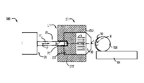
As shown in FIG. 3, a neutron capture therapy system in this embodiment is
preferably
a boron neutron capture therapy system 100, which includes a neutron
generating device 10,
a beam shaping assembly 20, a collimator 30, and a treatment table 40. The
neutron
generating device 10 includes an accelerator 11 and a target T, and the
accelerator 11
accelerates charged particles (such as protons, deuterons, etc.) to generate a
charged particle
beam P such as a proton beam, and the charged particle beam P irradiates the
target T and
interacts with the target T to generate neutrons which form a neutron beam N,
the neutron
beam define a main axis X, and the target T is a metal target. The neutron
beam N direction
described below with reference to the accompanying drawings does not represent
the actual
neutron motion direction, but the overall motion trend direction of the
neutron beam N.
Suitable nuclear reactions are always determined according to such
characteristics as desired
neutron yield and energy, available accelerated charged particle energy and
current and
materialization of the metal target, among which the most discussed two are
'Li (p, n) 'Be
and 9Be (p, n) 9B and both are endothermic reaction. Their energy thresholds
are 1.881 MeV
and 2.055 MeV respectively. Epithermal neutrons at a keV energy level are
considered ideal
neutron sources for BNCT. Theoretically, bombardment with lithium target using
protons
with energy slightly higher than the thresholds may produce neutrons
relatively low in energy,
so the neutrons may be used clinically without many moderations. However, Li
(lithium) and
Be (beryllium) and protons of threshold energy exhibit not high action cross
section. In order
to produce sufficient neutron fluxes, high-energy protons are usually selected
to trigger the
nuclear reactions. The target, considered perfect, is supposed to have the
advantages of high
neutron yield, a produced neutron energy distribution near the epithermal
neutron energy
range (see details thereinafter), little strong-penetration radiation, safety,
low cost, easy
accessibility, high temperature resistance etc. But in reality, no nuclear
reactions may satisfy
all requests. However, well known by those skilled in the art, the target
materials may be
13
Date Recue/Date Received 2021-09-29
CA 03135517 2021-09-29
made of other metals besides Li or Be, for example, tantalum (Ta) or tungsten
(W) or their
alloys. The accelerator 11 may be a linear accelerator, a cyclotron, a
synchrotron, a
synchrocyclotron.
Only mixed radiation fields are produced from BNCT neutron sources, that is,
beams
include neutrons and photons having energies from low to high. As for BNCT in
the depth
of tumors, except the epithermal neutrons, the more the residual quantity of
radiation ray is,
the higher the proportion of nonselective dose deposition in the normal tissue
is. Therefore,
radiation causing unnecessary dose should be lowered down as much as possible.
Besides air
beam quality factors, dose is calculated using a human head tissue prosthesis
in order to
understand dose distribution of the neutrons in the human body. The prosthesis
beam quality
factors are later used as design reference to the neutron beams, which is
elaborated hereinafter.
The International Atomic Energy Agency (IAEA) has given five suggestions on
the air
beam quality factors for the clinical BNCT neutron sources. The suggestions
may be used
for differentiating the neutron sources and as reference for selecting neutron
production
pathways and designing the beam shaping assembly, and are shown as follows:
Epithermal neutron flux > 1 x 10⁹ n/cm25
Fast neutron contamination <2 x 10-13 Gy-cm2/n
Photon contamination <2 x 10-13 Gy-cm2/n
Thermal to epithermal neutron flux ratio <0.05
Epithermal neutron current to flux ratio > 0.7
Note: the epithermal neutron energy range is between 0.5 eV and 40 keV, the
thermal
neutron energy range is lower than 0.5 eV, and the fast neutron energy range
is higher than
40 keV.
1. Epithermal neutron flux
The epithermal neutron flux and the concentration of the boronated
pharmaceuticals at
the tumor site codetermine clinical therapy time. If the boronated
pharmaceuticals at the
tumor site are high enough in concentration, the epithermal neutron flux may
be reduced. On
14
Date Recue/Date Received 2021-09-29
CA 03135517 2021-09-29
the contrary, if the concentration of the boronated pharmaceuticals in the
tumors is at a low
level, it is required that the epithermal neutrons in the high epithermal
neutron flux should
provide enough doses to the tumors. The given standard on the epithermal
neutron flux from
IAEA is more than 109 epithermal neutrons per square centimeter per second. In
this flux of
neutron beams, therapy time may be approximately controlled shorter than an
hour with the
boronated pharmaceuticals. Thus, except that patients are well positioned and
feel more
comfortable in shorter therapy time, and limited residence time of the
boronated
pharmaceuticals in the tumors may be effectively utilized.
2. Fast neutron contamination
Unnecessary dose on the normal tissue produced by fast neutrons is considered
as
contamination. The dose exhibits positive correlation to neutron energy,
hence, the quantity
of the fast neutrons in the neutron beams should be reduced to the greatest
extent. Dose of
the fast neutrons per unit epithermal neutron flux is defined as the fast
neutron contamination,
and according to IAEA, it is supposed to be less than 2*10-13 Gy-cm2/n.
3. Photon contamination (gamma-ray contamination)
Gamma-ray long-range penetration radiation will selectively result in dose
deposit of all
tissues in beam paths, so that lowering the quantity of gamma-ray is also the
exclusive
requirement in neutron beam design. Gamma-ray dose accompanied per unit
epithermal
neutron flux is defined as gamma-ray contamination which is suggested being
less than 2*10-
13 Gy-cm2/n according to IAEA.
4. Thermal to epithermal neutron flux ratio
The thermal neutrons are so fast in rate of decay and poor in penetration that
they leave
most of energy in skin tissue after entering the body. Except for skin tumors
like
melanocytoma, the thermal neutrons serve as neutron sources of BNCT, in other
cases like
brain tumors, the quantity of the thermal neutrons has to be lowered. The
thermal to
epithermal neutron flux ratio is recommended at lower than 0.05 in accordance
with IAEA.
5. Epithermal neutron current to flux ratio
The epithermal neutron current to flux ratio stands for beam direction, the
higher the
Date Recue/Date Received 2021-09-29
CA 03135517 2021-09-29
ratio is, the better the forward direction of the neutron beams is, and the
neutron beams in the
better forward direction may reduce dose surrounding the normal tissue
resulted from neutron
scattering. In addition, treatable depth as well as positioning posture is
improved. The
epithermal neutron current to flux ratio is better of larger than 0.7
according to IAEA.
The prosthesis beam quality factors are deduced by virtue of the dose
distribution in the
tissue obtained by the prosthesis according to a dose-depth curve of the
normal tissue and the
tumors. The three parameters as follows may be used for comparing different
neutron beam
therapy effects.
1. Advantage depth
Tumor dose is equal to the depth of the maximum dose of the normal tissue.
Dose of the
tumor cells at a position behind the depth is less than the maximum dose of
the normal tissue,
that is, boron neutron capture loses its advantages. The advantage depth
indicates
penetrability of neutron beams. Calculated in cm, the larger the advantage
depth is, the larger
the treatable tumor depth is.
2. Advantage depth dose rate
The advantage depth dose rate is the tumor dose rate of the advantage depth
and also
equal to the maximum dose rate of the normal tissue. It may have effects on
length of the
therapy time as the total dose on the normal tissue is a factor capable of
influencing the total
dose given to the tumors. The higher it is, the shorter the irradiation time
for giving a certain
dose on the tumors is, calculated by cGy/mA-min.
3. Advantage ratio
The average dose ratio received by the tumors and the normal tissue from the
brain
surface to the advantage depth is referred to as an advantage ratio. The
average ratio may be
calculated using dose-depth curvilinear integral. The higher the advantage
ratio is, the better
the therapy effect of the neutron beams is.
To provide comparison reference to design of the beam shaping assembly, we
also
provide the following parameters for evaluating expression advantages and
disadvantages of
the neutron beams in the embodiments of the present disclosure except the air
beam quality
16
Date Recue/Date Received 2021-09-29
CA 03135517 2021-09-29
factors of IAEA and the abovementioned parameters.
1. Irradiation time <30 min (proton current for accelerator is 10 mA)
2. 30.0 RBE-Gy treatable depth>7 cm
3. The maximum tumor dose>60.0 RBE-Gy
4. The maximum dose of normal brain tissue <12.5 RBE-Gy
5. The maximum skin dose <11.0 RBE-Gy
Note: RBE stands for relative biological effectiveness. Since photons and
neutrons
express different biological effectiveness, the dose above should be
multiplied with RBE of
different tissues to obtain equivalent dose.
The neutron beam N generated by the neutron generating device 10 sequentially
passes
through the beam shaping assembly 20 and the collimator 30 and then irradiates
to a patient
200 on the treatment table 40. The beam shaping assembly 20 is capable of
adjusting the
beam quality of the neutron beam N generated by the neutron generating device
10, and the
collimator 30 is provided to concentrate the neutron beam N, so that the
neutron beam N has
higher targeting during the treatment process. The beam shaping assembly 20
further includes
a support part 21 (not shown in Fig. 1, detailed below) and a main part 23
filled within the
support part 21, the support part 21 forms at least one accommodating unit C 1
-C 10, each
containing at least a portion of the main part 23. The support part may
prevent the
deformation and damage of the material of the main part and affect the target
replacing and
quality of the beam. The main part 23 includes a moderator 231, a reflector
232, a radiation
shield 233. The neutrons generated by the neutron generating device 10 have a
wide spectrum
of energy, and in addition to epithermal neutrons to meet treatment needs, it
is desirable to
reduce other types of neutrons and photons as much as possible to avoid injury
to operators
or patients. Therefore, the neutrons coming out of the neutron generating
device 10 need to
pass through the moderator 231 to adjust the energy of fast neutrons therein
to the epithermal
neutron energy region. The moderator 231 is made of a material having a cross
section for
principally acting with fast neutrons but hardly acting with epithermal
neutrons, such as
includes at least one of D20, A1F3, Fluental, CaF2, Li2CO3, MgF2 and A1203.
The reflector
17
Date Recue/Date Received 2021-09-29
CA 03135517 2021-09-29
232 surrounds the moderator 231, and reflects the neutrons diffused through
the moderator
231 back to the neutron beam N to improve the utilization of the neutrons, and
is made of a
material having high neutron reflection ability, such as includes at least one
of Pb and Ni.
The radiation shield 233 is provided to shield against leaking neutrons and
photons so as to
reduce dose of a normal tissue not exposed to irradiation. The material of the
radiation shield
233 includes at least one of a photon shielding material and a neutron
shielding material, such
as a photon shielding material lead (Pb) and a neutron shielding material
polyethylene (PE).
It should be appreciated that the main part may have other configurations as
long as the
epithermal neutron beam required for treatment may be obtained.
The target T is disposed between the accelerator 11 and the beam shaping
assembly 20,
and the accelerator 11 has a transmitting tube 111 that transmits the charged
particle beam P.
In this embodiment, the transmitting tube 111 penetrates into the beam shaping
assembly 20
in the direction of the charged particle beam P, and sequentially passes
through the moderator
231 and the reflector 232. The target T is arranged into the moderator 231 and
located at the
end of the transmitting tube 111 to obtain a better neutron beam quality. In
this embodiment,
first and second cooling pipes D1 and D2 are disposed between the transmitting
tube 111 and
the moderator 231, and between the transmitting tube 111 and the reflector
232, and one end
of the first and second cooling pipes D1, D2 is respectively connected to the
cooling inlet IN
(not shown in Figs) and the cooling outlet OUT (not shown in Figs) of the
target T, and the
other ends are connected to an external cooling source (not shown in Figs). It
should be
understood that the first and second cooling tubes may also be disposed into
the beam shaping
assembly in other ways, and may also be omitted when the target is placed
outside the beam
shaping assembly.
Referring to FIG. 4 and FIG. 5, the support part 21 includes an outer wall 211
circumferentially closed around the main axis X and a first side plate 221 and
a second side
plate 222 respectively disposed on two sides of the outer wall 211 in a
direction of the neutron
beam N and connected to the outer wall 211, a hole 2211 for a transmitting
tube 111 to pass
through is provided in the first side plate 221, a hole 2221 for forming a
beam exit is provided
in the second side plate 222, an accommodating portion C is formed between the
outer wall
18
Date Recue/Date Received 2021-09-29
CA 03135517 2021-09-29
211, the first side plate 221, and the second side plate 222, and the main
part 23 is disposed
in the accommodating portion C. The accommodating portion C includes at least
one
accommodating unit C 1 -C4 (described in detail below), each accommodating
unit C 1 -C4
accommodates at least one of the moderator 231, the reflector 232, and the
radiation shield
233, the at least one accommodating unit Cl-C4 accommodates at least two of
the moderator,
the reflector, and the radiation shield, or accommodates at least two
different materials. It
may be understood that the first side plate and the second side plate may not
be disposed, and
the outer wall surrounds the accommodating portion.
The support part 21 further includes at least one inner wall circumferentially
closed
around the main axis X and extending between the first side plate 221 and the
second side
plate 222. In this embodiment, a first inner wall 212 and a second inner wall
213 are disposed
inward in a radial direction, and the radial direction is defined as a
direction perpendicular to
the main axis X. The support part 21 further includes a first transverse plate
223 disposed
between the first side plate 221 and the second side plate 222 in the
direction of the neutron
beam N, a third inner wall 214 circumferentially closed around the main axis X
and extending
between the first transverse plate 223 and the first side plate 221, and a
fourth inner wall 215
circumferentially closed around the main axis X and extending from the first
transverse plate
223 to the second side plate 222. The third inner wall 214 is closer to the
main axis X in the
radial direction than the second inner wall 213, the fourth inner wall 215 is
located radially
between the second inner wall 213 and the third inner wall 214, and the first
transverse plate
223 extends between the third inner wall 214 and the fourth inner wall 215. An
inner surface
of the third inner wall 214 is on the same surface as a side wall of the hole
2211 in the first
side plate 221, and the third inner wall 214 forms a mounting portion for the
transmitting
tube 111, the first cooling pipe D1, the second cooling pipe D2, and the like.
A second
transverse plate 224 is disposed between the fourth inner wall 215 and the
second side plate
222 and is adjacent to the fourth inner wall 215 in the direction of the
neutron beam N, the
second transverse plate 224 extends radially inward from the second inner wall
213, a hole
2241 for the neutron beam N to pass through is provided in the second
transverse plate 224,
and an inner wall of the hole 2241 is closer to the main axis X than an inner
side of the fourth
inner wall 215. It may be understood that the second transverse plate may not
be disposed,
19
Date Recue/Date Received 2021-09-29
CA 03135517 2021-09-29
the first transverse plate may extend to the outer wall or another inner wall,
and a plurality
of transverse plates may be alternatively disposed between the outer wall and
the inner wall,
and between the inner walls.
In this embodiment, the entire beam shaping assembly is cylindrical, cross
sections of
the outer wall and the inner wall in a direction perpendicular to the main
axis X are rings
around the main axis X and extend parallel to the main axis X, and the side
plate and the
transverse plate are flat plates extending perpendicular to the main axis X.
It may be
understood that, there may be alternatively another arrangement. For example,
the extension
direction is inclined to the main axis, and an outer contour of the outer wall
in a direction
perpendicular to the main axis may be alternatively square, rectangular, or
polygonal, which
is convenient for transportation and mounting. A first accommodating unit Cl
is formed
between the outer wall 211, the first inner wall 212, the first side plate
221, and the second
side plate 222. A second accommodating unit C2 is formed between the first
inner wall 212,
the second inner wall 213, the first side plate 221, and the second side plate
222. A third
accommodating unit C3 is formed between the second inner wall 213, the third
inner wall
214, the fourth inner wall 215, the first side plate 221, the first transverse
plate 223, and the
second transverse plate 224.
In this embodiment, a PE block 241 of a corresponding shape is disposed in the
first
accommodating unit Cl, a lead block 242 and the PE block 241 are sequentially
disposed in
the second accommodating unit C2 in the direction of the neutron beam N, the
volume ratio
of the lead block to the PE block is less than or equal to 10, and an
interface between the lead
block and the PE block is perpendicular to the direction of the neutron beam
N. It may be
understood that there may be alternatively other ratios or other
distributions. In this
embodiment, the radiation shield 233 includes a neutron shield and a photon
shield, the PE
block 241 is provided as the neutron shield, and the lead block 242 is
provided as the reflector
232 and the photon shield.
In this embodiment, the lead block 242, an aluminum alloy block 243, a Teflon
block
244, and the PE block 241 are disposed in the third accommodating unit C3, the
aluminum
alloy block 243 and the Teflon block 244 are integrally disposed as a shape
including at least
Date Recue/Date Received 2021-09-29
CA 03135517 2021-09-29
one tapered shape, the PE block 241 is disposed adjacent to the second
transverse plate 224,
the lead block 242 fills the remaining region, and the aluminum alloy block
243 and the
Teflon block 244 divide the lead block 242 in the third accommodating unit C3
into two
portions. The aluminum alloy block 243 and the Teflon block 244 are
respectively provided
as the first supplementary unit and the second supplementary unit of the
moderator 231, so
that manufacturing costs of the moderator may be reduced, and the beam quality
is not
significantly affected. The first supplementary unit and the second
supplementary unit are
disposed as a shape including at least one tapered shape, so that better beam
quality and a
better treatment effect may be achieved. The Teflon block 244 also has a
better fast neutron
absorption effect, so that the content of fast neutrons in the beam may be
reduced. The lead
block 242 is provided as the reflector 232 and the photon shield. The PE block
241 is provided
as the neutron shield. It may be understood that the PE block may not be
disposed.
Referring to FIG. 6, in this embodiment, the aluminum alloy block 243 and the
Teflon
block 244 are sequentially disposed in the direction of the neutron beam N,
the aluminum
alloy block 243 and the Teflon block 244 are disposed as two tapered shapes
adjacent to each
other in opposite directions, the aluminum alloy block 243 is also disposed as
two tapered
shapes adjacent to each other in opposite directions, the aluminum alloy block
243 includes
a first tapered section 2431 and a second tapered section 2432 that are
sequentially disposed
in the direction of the neutron beam N, the radial size of an outer contour of
the first tapered
section 2431 gradually increases in the direction of the neutron beam N as a
whole, the second
tapered section 2432 is connected to the first tapered section 2431 at a
position where the
radial size of the outer contour of the first tapered section 2431 is maximum,
and the radial
size of an outer contour of the second tapered section 2432 gradually
decreases in the
direction of the neutron beam N as a whole. The Teflon block 244 is adjacent
to the second
tapered section 2432 at a position where the radial size of the outer contour
of the second
tapered section 2432 is minimum, the radial size of an outer contour of the
Teflon block 244
gradually decreases in the direction of the neutron beam N as a whole, and the
Teflon block
is in contact with the PE block 241 at a position where the radial size of the
outer contour is
maximum. Cross section contours of the aluminum alloy block 243 and the Teflon
block 244
in a plane where the main axis X is located are irregular quadrilaterals or
polygons. The
21
Date Recue/Date Received 2021-09-29
CA 03135517 2021-09-29
aluminum alloy block 243 has a first side Al in contact with the lead block
242 in the first
tapered section 2431, a second side A2 in contact with the lead block 242 and
a third side A3
in contact with the Teflon block 244 in the second tapered section 2432, and a
fourth side A4
in contact with the third inner wall 214, the fourth inner wall 215, and the
first transverse
plate 223 in the first tapered section and the second tapered section. In this
embodiment, the
fourth side A4 is a stepped surface. The Teflon block 244 has a fifth side AS
in contact with
the aluminum alloy block 243, a sixth side A6 in contact with the lead block
242, a seventh
side A7 in contact with the fourth inner wall 215, and an eighth side A8 in
contact with the
PE block 241. The third side A3 and the fifth side AS are adjacent to each
other and are
provided as an interface between the aluminum alloy block 243 and the Teflon
block 244. In
this embodiment, the interface is perpendicular to the direction of the
neutron beam N. In this
embodiment, the volume ratio of the aluminum alloy block 243 to the Teflon
block 244 is 5
to 20. It may be understood that there may be alternatively other ratios or
other distributions
according to the neutron beam required for treatment, for example, different
irradiation
depths.
A region from the first transverse plate 223 to the second transverse plate
224 in the
direction of the neutron beam N and surrounded by the fourth inner wall 215
forms a fourth
accommodating unit C4, and the fourth accommodating unit C4 is adjacent to the
third
accommodating unit C3 in the radial direction. In this embodiment, a magnesium
fluoride
.. block 245 is disposed in the fourth accommodating unit C4 as the basic
portion of the
moderator 231, and the magnesium fluoride block 245 contains Li-6 and is also
provided as
a thermal neutron absorber, so that the first supplementary unit and the
second supplementary
unit of the moderator disposed in the third accommodating unit C3 surround the
basic portion
of the moderator disposed in the fourth accommodating unit C4. The entire
magnesium
.. fluoride block 245 is cylindrical, including a first end surface A9 and a
second end surface
A10 that are approximately perpendicular to the direction of the neutron beam
N. The first
end surface A9 and the second end surface A10 are sequentially disposed in the
direction of
the neutron beam. The first end surface A9 faces the first side plate 221 and
is provided with
a center hole 2451. The center hole 2451 is provided to accommodate the
transmitting tube
111, the first cooling pipe D1, the second cooling pipe D2, and the target T.
The center hole
22
Date Recue/Date Received 2021-09-29
CA 03135517 2021-09-29
2451 is a cylindrical hole. A side wall 2451a of the center hole is on the
same surface as an
inner surface of the third inner wall. A radial distance Li from the third
inner wall 214 to the
main axis X is less than a radial distance L2 from the fourth inner wall 215
to the main axis
X, and the basic portion of the moderator 231 surrounds the target T, so that
the neutrons
generated by the target T may be effectively moderated in all directions, so
that the neutron
flux and beam quality may be further improved. The lead plate 246 is disposed
between the
magnesium fluoride block 245 and the second transverse plate 224. The lead
plate 246 is
provided as the photon shield, and lead may absorb gamma rays released from
the moderator.
A thickness of the lead plate 246 in the direction of the neutron beam N is
less than or equal
to 5 cm, so that neutrons passing through the moderator are not reflected. It
may be
understood that, there may be alternatively another arrangement. For example,
the
magnesium fluoride block 245 does not contain Li-6, but a separate thermal
neutron absorber
composed of Li-6 is disposed between the magnesium fluoride block 245 and the
second
transverse plate 224, and the lead plate may be alternatively omitted.
It may be understood that, in this embodiment, PE used for the neutron shield
may be
replaced with another neutron shielding material; lead used for the photon
shield may be
replaced with another photon shielding material; lead used for the reflector
may be replaced
with another material with high neutron reflection capability; magnesium
fluoride used for
the basic portion of the moderator may be replaced with another material
having a large cross
section for interacting with fast neutrons and a small cross section for
interacting with
epithermal neutrons; Li-6 used for the thermal neutron absorber may be
replaced with another
material having a large cross section for interacting with thermal neutrons;
the aluminum
alloy used for the first supplementary unit of the moderator may be replaced
with a material
including at least one of Zn, Mg, Al, Pb, Ti, La, Zr, Bi, Si, and C, and an
easily available
material is selected, so that manufacturing costs of the moderator may be
reduced, particular
neutron moderation is implemented, and the beam quality is not significantly
affected; and
Teflon used for the second supplementary unit of the moderator may be replaced
with
graphite and others, and A material with a better fast neutron absorption
effect than the
material of the first supplementary unit is selected for the second
supplementary unit, so that
the content of fast neutrons in the beam may be reduced. It may be understood
that at least
23
Date Recue/Date Received 2021-09-29
CA 03135517 2021-09-29
two of the first supplementary unit, the second supplementary unit, and the
basic portion of
the moderator may be alternatively made of the same material.
Referring to FIG. 7 and FIG. 8, the support part 21 is further provided with
radial
partitions 210, a plane where the radial partition 210 is located extends
through the main axis
X, and each of the accommodating units Cl to C3 is circumferentially divided
into at least
two subregions, so that the PE block, the lead block, the aluminum alloy
block, and the
graphite block disposed in each of the accommodating units Cl to C3 are
circumferentially
equally divided into at least two submodules. In this embodiment, a first
radial partition 2101
is disposed between the first side plate 221 and the second side plate, and
extends from the
outer wall 211 to the second inner wall 213; and a second radial partition
2102 is disposed
between the first side plate 221 and the second transverse plate 224, and
extends from the
second inner wall 213 to the third inner wall 214 or the fourth inner wall
215. In this
embodiment, there are eight first radial partitions and four second radial
partitions, all evenly
distributed circumferentially; and the first radial partitions and the second
radial partitions
are flat plates, and each second radial partition and four of the first radial
partitions are in the
same plane. It may be understood that there may be alternatively other
quantities or
arrangements of the radial partition, or the radial partition may not be
disposed.
In this embodiment, the radial partitions 210, the outer wall 211, the first
transverse plate
223, and the first, second, third, and fourth inner walls 212-215 are
integrated as a main frame
21a, and the material is an aluminum alloy with adequate mechanical properties
and a short
half-life of radioactive isotopes generated by the aluminum alloy after
activation by neutrons.
A casting process may be used, and a support mold is integrally formed. The
mold is a
wooden or aluminum mold, and a sand core may be red sand or resin sand. The
specific
process is the method commonly used in the industry. Because there are
demolding slopes
by casting, according to the requirements of design and beam quality, the
demolding slopes
need to be removed by machining. Due to the structure and casting process, the
frame
structure has the advantages of adequate integrity, high rigidity, and high
bearing capacity.
Due to the limitation of cutting tools of machining and stress concentration
on right-angle
sides, all corners are rounded. Alternatively, a plate may first be rolled and
welded or forged
24
Date Recue/Date Received 2021-09-29
CA 03135517 2021-09-29
into an aluminum alloy cylinder, and the cylinder is then machined for
formation.
FIG. 9 shows an embodiment of the main frame during processing. In this
embodiment,
the main frame 21a is a 6061 aluminum alloy, which may meet the requirements
of chemical
composition and mechanical properties of the material of the main frame. To
meet the
requirement of a short half-life of radioactive isotopes generated by the main
frame after
activation by neutrons, types of elements of the aluminum alloy and mass
ratios of the
elements should be controlled. For example, the mass percentage of Cu is < 7%.
Based on
relevant calculations and experience accumulation, the chemical composition of
the material
of the main frame selected in this embodiment is Cu < 1.0%, Mn < 1.5%, and Zn
< 1.0%
(mass percentage). The chemical composition of 6061 aluminum alloy is shown in
Table 1,
and it may be learned from the comparison that 6061 aluminum alloy may meet
the chemical
composition required by the material of the main frame 21a.
Table 1. Chemical composition (%)
Others
Cu Mn Mg Zn Cr Ti Si Fe Al
Single Total
0.15- 0.8- 0.04-
0.15 0.25 0.15 0.4-0.8 0.7
0.05 0.15 Allowance
0.4 1.2 0.35
To meet the support of the main frame 21a on the main part 23 of the beam
shaping
assembly, the mechanical properties of the main frame need to meet the
requirements.
According to CAE simulation calculation and empirical adjustments, for the
aluminum alloy
main frame selected in this embodiment, the tensile strength is > 150 1ViPa,
and the yield
strength is > 100 MPa.
Because 6061 aluminum alloy is a wrought aluminum alloy, a free forging method
is
used in this embodiment, the structure and properties of the aluminum alloy
are changed by
using a plastic forming method, and raw materials may be saved. In the free
forging
procedure, the quality of a forging largely depends on a metal structure
obtained during
deformation, especially the uniformity of forging deformation. Nonuniform
deformation
reduces the plasticity of the metal, and a non-homogenized structure is
obtained due to
nonuniform recrystallization, so that forging properties become poor. To
obtain a uniform
Date Recue/Date Received 2021-09-29
CA 03135517 2021-09-29
deformed structure and optimal mechanical properties, the fewer procedures and
the fewer
heating times, the better. The processing of this embodiment is as follows:
1. Blank material preparation: Manufacturers such as aluminum factories treat
aluminum
ore into aluminum ingots, cast the aluminum ingots into a blank material,
prepare the blank
material into the composition of 6061 aluminum alloy that meets the national
standard, and
detect the blank material, for example, attached with data and experimental
results in the
aspects such as an alloy number, a melting furnace, a batch number,
specifications,
homogenization annealing, low-temperature roasting, an oxide film inspection.
2. Cutting: The blank material that meets the detection requirements is
treated by using
methods such as shearing, sawing, and gas cutting. For example, end surface
cutting is
performed, and buns, oil stains, and sawdust are removed in time, to meet the
processing
requirements of forging equipment.
3. Heating: The blank material is heated before forging to reduce deformation
resistance
and improve plasticity. For example, a radiant resistance heating furnace is
used, there is
circulating air in the furnace to keep the temperature accurate and uniform,
and the furnace
temperature deviation may be controlled in a range of 10 C. In this
embodiment, the
maximum initial forging temperature is 520 C, the final forging temperature is
450 C, and
the allowable limit temperature is 530 C. It may be understood that other
heating equipment
may be alternatively used. The determination of a heat preservation time needs
to fully
consider factors such as the thermal conductivity of an alloy, blank material
specifications,
heat transfer modes of heating equipment, and the like. In this embodiment,
the heating time
is determined according to dissolution of a strengthening phase and structure
homogenization.
In this state, adequate plasticity may be obtained, and the forging
performance of an
aluminum alloy may be improved. It may be understood that the blank material
may be
alternatively heated before the cutting in step 2. In this case, before the
blank material is
heated, for example, before the blank material enters a heating furnace, it is
necessary to
remove oil stains, dust, and other dirt to avoid polluting air in the furnace.
4. Forging: The material of 6061 aluminum alloy is polycrystalline, there are
grain
boundaries between grains, and there are subgrains and phase boundaries inside
the grains.
26
Date Recue/Date Received 2021-09-29
CA 03135517 2021-09-29
Therefore, the material is subjected to plastic deformation based on the
plasticity of the
material by using an external force to obtain a forging with the required
shape (for example,
a cylinder), size, and particular structural properties. A cast structure of
the metal blank
material is eliminated through forging deformation, thereby greatly improving
the plasticity
and mechanical properties. In this embodiment, a free forging method such as
upsetting and
drawing is used, under the condition that the forging temperature is not less
than a specified
temperature, static forging is repeated according to processes of the
foregoing two methods
to obtain precise grains in the structure, and the forging equipment has the
precision of
forging a blank.
5. Rough machining and heat treatment: To finally obtain the mechanical
properties that
meet the requirements of use, it is also necessary to change the structure and
properties of
the metal material through heat treatment to change the internal quality of
the metal. In this
embodiment, a cylinder is obtained by forging in step 4. When heat treatment
is directly
performed on the cylinder, it is difficult to ensure the performance of a
material at the center
of the cylinder. Therefore, a hole is drilled at a center position (that is,
the regions of the
cylinder corresponding to the fourth accommodating unit C4) of the forged
cylinder through
rough machining, and deep heat treatment is then performed, so that it may be
ensured that
the main frame is close to the center position (to form a main frame portion
of the fourth
accommodating unit C4) and ensure the overall material properties after the
heat treatment.
In addition, the fourth accommodating unit C4 accommodates the basic portion
of the
moderator, so that the support for the moderator may be ensured, and the
moderator is
prevented from deformation and damage, to avoid affecting the target change
and beam
quality. It may be understood that the rough machining further includes
preliminary
machining of hollow regions (that is, regions of the cylinder corresponding to
the first
accommodating unit Cl, the second accommodating unit C2, and the third
accommodating
unit C3) between the outer wall 211 and the inner walls 212-215 of the main
frame, for
example, a solid portion of the cylinder obtained by forging in the regions is
drilled and
milled. In this embodiment, the rough machining is not performed in the
regions, to prevent
the regions from easy deformation caused by a thin thickness during heat
treatment after the
rough machining. In the case that the process may ensure the material
properties of a center
27
Date Recue/Date Received 2021-09-29
CA 03135517 2021-09-29
region and other regions, the rough machining may not be performed. The rough
machining
should leave an allowance for subsequent machining.
The heat treatment used in this embodiment is T6 (solid solution+aging).
Solution
treatment is a precedent procedure for precipitation hardening of an alloy. A
solid solution
formed during the solution treatment is rapidly cooled to obtain a metastable
supersaturated
solid solution, which creates conditions for natural aging and artificial
aging, and
significantly improves the strength and hardness. Aging treatment is required
after the
solution treatment, aluminum after solution treatment is kept at a particular
temperature for
a particular time, and a supersaturated solid solution decomposes to cause the
strength and
hardness of the alloy to increase greatly, and aluminum may be kept at room
temperature or
heated. The aging treatment is the last procedure of the heat treatment, which
may improve
and determine the final mechanical properties of the aluminum alloy. The
heating
temperature and the heat preservation time may be selected according to an
actual situation.
It may be understood that other heat treatment processes may be alternatively
used, as long
as the mechanical properties that meet the requirements of use may be met.
6. Physical and chemical testing and inspection: After the heat treatment,
physical and
chemical testing and inspection need to be performed, including size testing,
element testing,
mechanical property testing, non-destructive ultrasonic flaw detection
testing, and the like.
The testing may be performed after the heat treatment by relevant personnel of
the heat
treatment, or the inspection may be performed before machining by relevant
personnel of the
machining (see below). The mechanical property testing may be performed by
cutting part
of the material in a relevant region of a workpiece after the heat treatment.
In this embodiment,
the part removed by drilling a hole at the center position may be subjected to
the heat
treatment during the rough machining, and the part is tested to approximately
represent the
properties of the inner walls 214 and 215 close to the main axis X; and the
region between
the outer wall 211 and the inner walls 212-215 is tested by cutting the
material of the forged
cylinder after heat treatment in this region. It may be understood that, when
the rough
machining is performed on the hollow regions between the outer wall 211 and
the inner walls
212-215, the part cut off by performing rough machining on the region is
tested after heat
28
Date Recue/Date Received 2021-09-29
CA 03135517 2021-09-29
treatment to approximately represent the properties of the region, and the
selection of the
region may be marked on a drawing. The foregoing region is sampled for
mechanical testing
to obtain the yield strength and tensile strength. The non-destructive testing
uses ultrasonic
flaw detection, which may be comprehensive inspection or partition inspection.
In this
embodiment, the ultrasonic flaw detection testing is performed on the inner
wall close to the
center.
7. Machining: After testing and inspection, and a forged body after the heat
treatment
meets the requirements, machining is performed to obtain the main frame with a
final
required shape and size. It may be understood that the machining may include
conventional
machining methods such as drilling, milling, and turning. In this embodiment,
a large gantry
milling machine is used for milling, and cooperates with programming software
for automatic
processing.
The main frame 21a and the second transverse plate 224 are connected by a
bolt. A first
threaded hole is uniformly machined in an end surface, facing the second side
plate 222, of
the fourth inner wall 215. A first through hole is uniformly machined at a
position,
corresponding to the first threaded hole, in the second transverse plate 224.
The bolt passes
through the first through hole to be connected to the first threaded hole. Due
to the assembly
of the bolt, the hole diameter of the first through hole is slightly greater
than the hole diameter
of the first threaded hole, and the quantities of the first threaded holes and
the first through
holes only need to meet the connection strength. The material of the first
side plate 221, the
second side plate 222, and the second transverse plate 224 is a lead-antimony
alloy. Lead
may further shield against radiation, and the lead-antimony alloy has a
relatively high
strength. The outer contours of the first side plate 221 and the second side
plate 222 are
consistent with the outer contour of the outer wall 211. The first side plate
221, the second
side plate 222, and the second transverse plate 224 are connected to the main
frame by bolts.
Second threaded holes are uniformly machined respectively in end surfaces,
facing the first
side plate, the second side plate, and the second transverse plate, of the
inner wall of the main
frame 21a. Second through holes are uniformly machined at positions,
corresponding to the
second threaded holes, of the first side plate 221, the second side plate 222,
and the second
29
Date Recue/Date Received 2021-09-29
CA 03135517 2021-09-29
transverse plate 224. Due to the assembly of the bolts, the hole diameter of
the second through
hole is slightly greater than the hole diameter of the second threaded hole,
and the quantities
of the second threaded holes and the second through holes only need to meet
the connection
strength.
It may be understood that, in this embodiment, the materials of the main
frame, the side
plate, and the end plate (the second transverse plate) only need to have a
particular strength
and a short half-life of radioactive isotopes generated by the materials after
activation by
neutrons (for example, less than 7 days), and the material properties of the
main frame may
meet the requirements of supporting the beam shaping assembly, such as an
aluminum alloy,
a titanium alloy, a lead-antimony alloy, cobalt-free steel, carbon fiber,
PEEK, or a high
polymer. Other detachable connections or non-detachable connections may be
provided
between the side plate, the end plate (the second transverse plate), and the
main frame. When
the detachable connection is used, it is convenient to replace each portion of
the main part.
In this embodiment, the support part and the main part filled within the
support part of the
beam shaping assembly may alternatively have another construction manner.
During construction, the main frame 21a is first put into a mounting hole
reserved by the
support part of the beam shaping assembly, and the outer wall 211 of the main
frame 21a and
the support part of the beam shaping assembly are connected by bolts. Filling
of the main
part and mounting of the first side plate, the second side plate, and the
second transverse plate
are then performed. Due to low density of PE, aluminum alloy, and graphite,
the
corresponding regions may be filled entirely. Because lead is relatively
heavy, lead may be
manually filled in pieces in the direction of the neutron beam N or may be
entirely filled with
a machine. Magnesium fluoride may also be filled entirely or in pieces. After
the beam
shaping assembly is mounted, the transmitting tube, the target, the
collimator, and other
components are mounted. The collimator 30 is disposed at a rear portion of the
beam exit.
The epithermal neutron beam from the collimator 30 is irradiated to the
patient 200, and is
moderated to be thermal neutrons after passing through superficial normal
tissues to reach a
tumor cell M. In this embodiment, the collimator is fixed to the main frame
21a by bolts, a
third threaded hole is reserved in an end surface, facing the second side
plate, of the second
Date Recue/Date Received 2021-09-29
CA 03135517 2021-09-29
inner wall 213, and a third through hole is uniformly machined at a position,
corresponding
to the third threaded hole, of the second side plate 222. Due to the assembly
of the bolt, the
hole diameter of the third through hole is slightly greater than the hole
diameter of the third
threaded hole, and the quantities of the third threaded holes and the third
through holes only
need to meet the connection strength. It may be understood that the collimator
30 may be
alternatively fixed in another connection manner, the collimator 30 may be
alternatively
removed or replaced with another structure, and the neutron beam from the beam
exit directly
irradiates the patient 200. In this embodiment, a radiation shielding device
50 is further
disposed between the patient 200 and the beam exit to shield normal tissue of
the irradiated
subject from irradiation by the beam from the beam exit. It should be
understood that the
radiation shielding device 50 may not be disposed.
The term 'cylindrical' or 'cylindrical section' referred in the embodiment of
the present
disclosure is an element with the contour in a substantially unchanged trend
from one side to
the other side along the illustrated direction. One of contour lines may be a
line segment, like
a corresponding one of the cylinder, or may be a high-curvature arc
approximate to the line
segment, like a corresponding one of a sphere with high curvature. The
integral surface of
the contour may be continuously connected or not if the surface of the
cylinder or the high-
curvature sphere is provided with many protrusions and grooves.
The term 'tapered' or 'tapered section' referred in the embodiment of the
present
disclosure is an element with the contour in a tapering trend from one to the
other side along
the illustrated direction. One of contour lines may be a line segment, like a
corresponding
one of the cone, or may be an arc, like a corresponding one of the sphere, and
the integral
surface of the contour may be continuously connected or not if the surface of
the cone shape
or the spherical shape is provided with plenty of protrusions and grooves.
Although the illustrative embodiments of the present invention have been
described
above in order to enable those skilled in the art to understand the present
invention, it should
be understood that the present invention is not to be limited the scope of the
embodiments.
For those skilled in the art, as long as various changes are within the spirit
and scope as
defined in the present invention and the appended claims, these changes are
obvious and
31
Date Recue/Date Received 2021-09-29
CA 03135517 2021-09-29
within the scope of protection claimed by the present invention.
32
Date Recue/Date Received 2021-09-29