Note: Descriptions are shown in the official language in which they were submitted.
SYSTEM AND METHOD FOR CHARGING BATTERIES IN ELECTRIC
APPARATUSES
CROSS REFERENCE TO RELATED APPLICATIONS
[0001] The present application claims priority to U.S. Patent Provisional
Application
62/986,232 filed March 6, 2020.
BACKGROUND
1. Technical Field
[0002] The present teaching generally relates to electric apparatuses. More
particularly,
the present teaching relates to methods and systems for charging batteries
deployed in electric
apparatuses.
2. Technical Background
[0003] Electric vehicles have increasingly becoming prevalent, accounting for
a growing
market share of vehicles on the road. However, ubiquitous use of electric
vehicles still faces some
challenges. Particularly, an electrical vehicle relies on batteries as its
sole power supply so that
batteries have to be recharged. Charging batteries for electrical vehicles
traditionally requires
special external equipment which is known as Electric Vehicle Supply Equipment
(EVSE,
sometimes called conductive charging systems, or electric vehicle charging
stations).
[0004] There are two main types of EVSEs. One type provides alternating-
current (AC)
electricity to the vehicle, with the vehicle's onboard charger converting AC
power to direct current
(DC) power needed to charge the batteries. An AC-based EVSE
1
Date recue/Date received 2023-03-17
CA 03136176 2021-10-05
WO 2021/176431
PCT/IB2021/051920
operates as an intermediary between an electric vehicle and an AC outlet,
generally using
household AC power as input. The actual charger is provided inside the vehicle
and usually
has a limited power capacity. As such, electric vehicles are generally
equipped with only
onboard chargers at a capacity of no more than 10 kW (for example, 6 or 7 kW).
If a user
desires to utilize a higher power level, the user will need to charge the
vehicles through the
other type of EVSEs, i.e., Direct Current output EVSEs or DC-based EVSEs.
[0005] DC-
based EVSEs are also known as "fast chargers." A DC EVSE
can transform alternating current power to direct current power, and thus can
bypass the
onboard charger on the electric vehicle to charge DC power directly to the
battery. As such
a charging operation is not constrained by the capacity limitation of the
onboard charger,
batteries can be charged at a significantly faster speed. Due to the fact that
DC EVSEs are
technologically much more complex and expensive as compared with AC EVSEs and
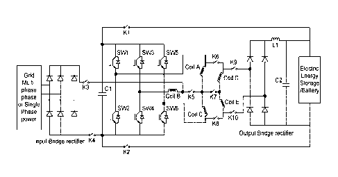
require high powered electric supply points, it is therefore found much fewer
applications
than AC EVSEs. Such issues related to the charging speed in combination with
the limited
available charging stations for vehicles have so far been a barrier to more
widespread
adoption of electric vehicles.
[0006] Thus,
there is a need to develop more effective means and methods
to charge batteries of electrical vehicles that address such deficiencies.
SUMMARY
[0007] The
teaching disclosed herein relates to methods and systems for
charging batteries deployed in electric apparatuses. More particularly, the
present teaching
2
CA 03136176 2021-10-05
WO 2021/176431
PCT/IB2021/051920
relates to methods and systems for operating reconfigurably under one of
traction and
charging operating modes.
[0008] In an
example, a reconfigurable traction-charging system residing in
an electric apparatus having a rechargeable battery is disclosed. The system
comprises a
motor, an inverter, an output rectifier, a configurator, and a controller. The
motor
comprises a stator which has a plurality of stator teeth and a plurality of
stator windings
wounded on the plurality of stator teeth. The inverter comprises a plurality
of power switch
devices. The configurator comprises a plurality of contactors coupled with the
plurality of
stator windings and the plurality of power switch devices. The controller
controls the
plurality of power switch devices and the plurality of contactors, so as to
configure the
system to operate in one of a traction mode and a charging mode.
[0009] In
another example, a method of implementing a reconfigurable
traction-charging system residing in an electric apparatus having a
rechargeable battery is
disclosed. The system is configured, via a configurator, under the control of
a controller,
to operate in a traction mode. Upon receiving a request to charge the
rechargeable battery,
the system is configured via the configurator to operate in a charging mode.
When it is
determined that a criterion associated the rechargeable battery is met, the
system is
configured via the configurator to operate in the traction mode. Besides the
configurator
and the controller, the system comprises a motor, an inverter, and an output
rectifier. The
motor comprises a stator having a plurality of stator teeth and a plurality of
stator windings
wound on the plurality of stator teeth. The inverter comprises a plurality of
power switch
devices. The configurator comprises a plurality of contactors coupled with the
plurality of
stator windings and the plurality of power switch devices.
3
CA 03136176 2021-10-05
WO 2021/176431
PCT/IB2021/051920
[0010]
Additional novel features will be set forth in part in the description
which follows, and in part will become apparent to those skilled in the art
upon examination
of the following and the accompanying drawings or may be learned by production
or
operation of the examples. The novel features of the present teachings may be
realized and
attained by practice or use of various aspects of the methodologies,
instrumentalities and
combinations set forth in the detailed examples discussed below.
BRIEF DESCRIPTION OF THE DRAWINGS
[0011] The
systems and methods disclosed herein are further described in
terms of exemplary embodiments. These exemplary embodiments are described in
detail
with reference to the drawings. The embodiments are non-limiting exemplary
embodiments, in which like reference numerals represent similar structures
throughout the
several views of the drawings, and wherein:
[0012] Fig. 1
shows an exemplary simplified circuit diagram related to a
conceptual charging power path, in accordance with an exemplary embodiment of
the
present teaching;
[0013] Fig.
2A shows an exemplary schematic drawing related to an
onboard charging-traction system, in accordance with an exemplary embodiment
of the
present teaching;
[0014] Fig.
2B shows an exemplary schematic drawing related to an
onboard charging-traction system, in accordance with an exemplary embodiment
of the
present teaching;
4
CA 03136176 2021-10-05
WO 2021/176431
PCT/IB2021/051920
[0015] Fig. 3
shows an exemplary structure of windings wound on teeth of
a motor stator, in accordance with an exemplary embodiment of the present
teaching;
[0016] Fig.
4A shows an exemplary schematic drawing related to an
onboard charging-traction system, in accordance with an exemplary embodiment
of the
present teaching;
[0017] Fig.
4B shows an exemplary simplified circuit diagram related to a
charging power path of an onboard charging-traction system, in accordance with
an
exemplary embodiment of the present teaching;
[0018] Fig.
4C shows an exemplary simplified circuit diagram related to a
traction power path of an onboard charging-traction system, in accordance with
an
exemplary embodiment of the present teaching;
[0019] Fig.
4D shows an exemplary schematic drawing related to an
onboard charging-traction system, in accordance with an exemplary embodiment
of the
present teaching;
[0020] Fig.
4E shows an exemplary simplified circuit diagram related to a
charging power path of onboard charging-traction system, in accordance with an
exemplary embodiment of the present teaching;
[0021] Fig.
4F shows an exemplary simplified circuit diagram related to a
traction power path of an onboard charging-traction system, in accordance with
an
exemplary embodiment of the present teaching;
[0022] Fig.
5A shows an exemplary schematic drawing related to an
onboard charging-traction system, in accordance with an exemplary embodiment
of the
present teaching;
CA 03136176 2021-10-05
WO 2021/176431
PCT/IB2021/051920
[0023] Fig.
5B shows an exemplary schematic drawing related to an
onboard charging-traction system, in accordance with an exemplary embodiment
of the
present teaching;
[0024] Fig.
6A shows an exemplary simplified circuit diagram related to an
onboard charging-traction system, in accordance with an exemplary embodiment
of the
present teaching;
[0025] Fig.
6B shows an exemplary simplified circuit diagram related to an
onboard charging-traction system, in accordance with an exemplary embodiment
of the
present teaching;
[0026] Fig.
6C shows an exemplary simplified circuit diagram related to an
onboard charging-traction system, in accordance with an exemplary embodiment
of the
present teaching;
[0027] Fig.
7A shows an exemplary schematic drawing related to an
onboard charging-traction system, in accordance with an exemplary embodiment
of the
present teaching;
[0028] Fig.
7B shows an exemplary schematic drawing related to an
onboard charging-traction system, in accordance with an exemplary embodiment
of the
present teaching;
[0029] Fig.
8A shows an exemplary simplified circuit diagram related to an
onboard charging-traction system, in accordance with an exemplary embodiment
of the
present teaching;
6
CA 03136176 2021-10-05
WO 2021/176431
PCT/IB2021/051920
[0030] Fig.
8B shows an exemplary simplified circuit diagram related to an
onboard charging-traction system, in accordance with an exemplary embodiment
of the
present teaching;
[0031] Fig.
8C shows an exemplary simplified circuit diagram related to an
onboard charging-traction system, in accordance with an exemplary embodiment
of the
present teaching;
[0032] Fig.
9A shows an exemplary schematic drawing related to an
onboard charging-traction system, in accordance with an exemplary embodiment
of the
present teaching;
[0033] Fig.
9B shows an exemplary schematic drawing related to an
onboard charging-traction system, in accordance with an exemplary embodiment
of the
present teaching;
[0034] Fig.
10A shows an exemplary simplified circuit diagram related to
an onboard charging-traction system, in accordance with an exemplary
embodiment of the
present teaching;
[0035] Fig.
10B shows an exemplary simplified circuit diagram related to
an onboard charging-traction system, in accordance with an exemplary
embodiment of the
present teaching;
[0036] Fig.
10C shows an exemplary simplified circuit diagram related to
an onboard charging-traction system, in accordance with an exemplary
embodiment of the
present teaching;
7
CA 03136176 2021-10-05
WO 2021/176431
PCT/IB2021/051920
[0037] Fig.
11A shows an exemplary schematic drawing related to an
onboard charging-traction system, in accordance with an exemplary embodiment
of the
present teaching;
[0038] Fig.
11B shows an exemplary schematic drawing related to an
onboard charging-traction system, in accordance with an exemplary embodiment
of the
present teaching;
[0039] Fig.
12A shows an exemplary simplified circuit diagram related to
an onboard charging-traction system, in accordance with an exemplary
embodiment of the
present teaching;
[0040] Fig.
12B shows an exemplary simplified circuit diagram related to
an onboard charging-traction system, in accordance with an exemplary
embodiment of the
present teaching;
[0041] Fig.
12C shows an exemplary simplified circuit diagram related to
an onboard charging-traction system, in accordance with an exemplary
embodiment of the
present teaching;
[0042] Fig.
13 shows an exemplary flowchart related to the operation of an
onboard charging-traction system, in accordance with an exemplary embodiment
of the
present teaching;
[0043] Fig.
14 shows an exemplary schematic drawing related to pre-
charging of a capacitor Cl, in accordance with an exemplary embodiment of the
present
teaching;
8
CA 03136176 2021-10-05
WO 2021/176431
PCT/IB2021/051920
[0044] Fig.
15A shows an exemplary schematic drawing related to
hardware components of an onboard charging-traction system, in accordance with
an
exemplary embodiment of the present teaching;
[0045] Fig.
15B shows an exemplary schematic drawing related to
hardware components of an onboard charging-traction system, in accordance with
an
exemplary embodiment of the present teaching;
[0046] Fig.
16 shows an exemplary schematic drawing related to
connection between a charging/traction controller and power switch devices, in
accordance
with an exemplary embodiment of the present teaching;
[0047] Fig.
17 shows an exemplary control scheme performed under a
charging mode of an onboard charging-traction system, in accordance with an
exemplary
embodiment of the present teaching;
[0048] Figs.
18A - 18G show exemplary schematic drawings related to
various connections of more than one motor and/or more than one battery of an
onboard
charging-traction system, in accordance with exemplary embodiments of the
present
teaching;
[0049] Fig.
19 shows an exemplary schematic drawing related to
connections of two or more charger-inverters and a battery, in accordance with
an
exemplary embodiment of the present teaching;
[0050] Fig.
20A shows an exemplary simplified circuit diagram related to
an onboard charging-traction system, in accordance with an exemplary
embodiment of the
present teaching; and
9
CA 03136176 2021-10-05
WO 2021/176431
PCT/IB2021/051920
[0051] Fig.
20B shows an exemplary simplified circuit diagram related to
an onboard charging-traction system, in accordance with an exemplary
embodiment of the
present teaching.
DETAILED DESCRIPTION
[0052] In the
following detailed description, numerous specific details are
set forth by way of examples in order to provide a thorough understanding of
the relevant
teachings. However, it should be apparent to those skilled in the art that the
present
teachings may be practiced without such details. In other instances, well
known methods,
procedures, components, circuitry, topological structures and/or control
strategies have
been described at a relatively high-level, without much detail, in order to
avoid
unnecessarily obscuring aspects of the present teachings.
[0053] The
present teaching aims to improve the current state of the art in
charging of rechargeable batteries. Particularly, the present teaching
discloses a combined,
reconfigurable, onboard traction and charging solution which can find
application in
electric apparatuses (including, e.g., electric vehicles, special purpose
electric vehicles, etc).
[0054] An
onboard traction-charging system revealed in the present
teaching includes a combination of reconfigurable motor phase windings and
inverters.
When operating in a traction mode, the system works as a traction mechanism
which is
capable of delivering mechanical power to a load, and under a charging mode,
it works as
an onboard charger which is capable of charging the battery or batteries
included in the
vehicle with high power. On the one hand, it is possible to perform recharging
rapidly with
a high power switched power supply; on the other hand, the costs of
establishing EVSEs
CA 03136176 2021-10-05
WO 2021/176431
PCT/IB2021/051920
(or charging stations) that supply AC electric power to the onboard traction-
charging
system can be reduced significantly.
[0055] The
onboard traction-charging system according to the present
teaching takes full advantage of two pre-existing components in the electric
vehicles: an
electric motor with stator windings, and a multiphase inverter with switch
power devices.
A switching mechanism, called a configurator herein, changes connections of
the motor
windings and of the power switch devices included in the inventor to allow
switching
between the two operating modes. When the onboard traction-charging system is
working
under the traction mode, the power switch devices constitute an inverter which
converts
the DC power outputted from the battery to corresponding AC voltage so as to
drives the
motor to provide a torque (positive or negative) to drive the vehicle. This
torque can either
transfer energy from the battery or recover energy in a dynamic braking mode.
When the
onboard traction-charging system is working under the charging mode, the
configurator
reconfigures the connection of the inverter and of the motor windings to form
one or more
front end (with or without a rectification function, a boost function, and/or
a power factor
correction (PFC) function), and one or more fully isolated DC/DC converter
rear end, so
as to achieve a fully isolated onboard charger.
[0056] Fig. 1
shows, in a simplified form, a conceptual charging power path
in accordance with an example of the present teaching. To facilitate
understanding, the
specifics pertaining to the shared components associated with the charging and
traction
modes are not shown in the simplified circuit diagram of Fig. 1.
[0057] As
shown in Fig. 1, the charging power path comprises an input
bridge rectifier or passive rectifier front end D1, which is electrically
coupled to a single-
11
CA 03136176 2021-10-05
WO 2021/176431
PCT/IB2021/051920
phase AC power input or a multi-phase AC power input. A boost converter serves
to boost
a DC voltage outputted from the input bridge rectifier or passive rectifier
front end D1 to
a regulated DC link voltage. The boost converter comprises a boost inductor
Li, a power
switch device Q1 and a power switch device Q2. The regulated DC link voltage
DC LINK
outputted from the boost converter is applied to a bridge converter comprising
two half
bridges (Q3 and Q4; Q5 and Q6). The output of the bridge converter drives a
transformer
Ti and in turn an output bridge rectifier D2 to produce isolated DC power for
charging the
battery. An inductor L2 and a capacitor C2 are used to filter and smooth the
DC power
outputted from the output bridge rectifier D2.
[0058] As
discussed in the above, although not shown in Fig. 1, the
charging power path can share a plurality of components with the traction
power path. The
concept of sharing the components will be described in detail at the below
with reference
to the appended drawings. The degree of components sharing between the
charging and
traction modes may vary depending on the details of the design. The
accompanying
drawings illustrate various ways to implement the inventive ideas and concepts
revealed in
the present teaching.
First Embodiment
[0059] Fig.
2A shows a schematic drawing related to an onboard charging-
traction system in accordance with the first embodiment. In Fig. 2A, certain
coils used to
construct the transformer under the charging mode are connected in parallel
when the
system is working under the traction mode. Fig. 2B shows another schematic
drawing
related to an onboard charging-traction system in accordance with the first
embodiment.
12
CA 03136176 2021-10-05
WO 2021/176431
PCT/IB2021/051920
In Fig. 2B, certain coils used to construct the transformer under the charging
mode are
connected in series when the system is working under the traction mode.
[0060] Except
for the difference in connection of the coils (in parallel or in
series under the traction mode), the onboard charging-traction systems shown
in Figs. 2A
and 2B both comprise a polyphase motor, a rechargeable battery, an inverter,
an input
rectifier, an output rectifier, a configurator and sets of contactors. The
polyphase motor
may comprise three or more phases of stator windings. In certain applications,
alternatively,
the motor may be a two-phase motor driven by two sets of half bridges. The
inverter
comprises a plurality of power switch devices SW1, SW2, SW3, SW4, SW5 and SW6,
and
serves to drive the polyphase motor. The power switch devices may have
different current
capacities. For example, depending on the output power level and/or the input
voltage
condition, the power switch devices SW3 and SW4, which are used to form a
Boost
converter in the charging mode, may have higher current capacity than that of
SW1, SW2,
SW5 and SW6. Depending on the input power is fed from a single phase or a
multiple
phase power supply, the input rectifier may be a single phase or a multiple
phase bridge
rectifier. When a DC power source is used to supply the charging power, the
input rectifier
may be omitted. The configurator comprises a plurality of contactors Kl, K2,
K3, K4, K5,
K6, K7, K8, K9 and K10. Under proper control, the configurator serves to re-
configure
connections of various components, in particular the connections among the
windings
and/or the power switch devices SW1, SW2, SW3, SW4, SW5 and SW6, so as to
switch
the system between different operation modes. The set of contactors K1 and K2
may be
used to connect and disconnect the positive and negative terminals of the
rechargeable
battery. More specifically, the contactors K1 and K2 are open under the
charging mode,
13
CA 03136176 2021-10-05
WO 2021/176431
PCT/IB2021/051920
and closed under the traction mode. The set of contactors K3 and K4 may be
used to
connect and disconnect the DC power rectified from the input AC power. The
contactors
K3 and K4 are closed under the charging mode, and open under the traction
mode.
[0061] In
addition, the systems shown in Figs. 2A and 2B may further
comprise an input filter and/or an output filter, which may be used to reduce
noise and
voltage or current ripple. These input and output filters may include, but not
limited to,
inductors and/or capacitors. A capacitor Cl may be linked to the input side of
the inverter.
Although the capacitor Cl is shown as a single one, it also can be multiple
capacitors or a
module with multiple capacitors packaged together. As an example of the output
filter, an
inductor Li and a capacitor C2 are shown in Figs. 2A and 2B. Although the
output
capacitor C2 is shown as a single one, it also can be multiple capacitors or a
module with
multiple capacitors packaged together. Although the output capacitor C2 is
shown as a
single one, it also can be multiple capacitors or a module with multiple
capacitors packaged
together. Alternatively, if the battery is capable to tolerate the ripple
current at the output
side of the output bridge rectifier, the capacitor C2 can be omitted.
[0062]
Although not shown in Figs. 2A and 2B, other circuit protection
components may be included in the system, including but not limited to pre-
charge circuits,
discharge circuits, inrush current protection circuits, etc.
[0063] As
discussed in the above, both onboard charging-traction systems
illustrated in Figs. 2A and 2B may be configured to operate under either one
of two working
modes, i.e., the charging mode and the traction mode. The details related to
the
configuration will be described at the below with reference to Figs. 4A-F.
14
CA 03136176 2021-10-05
WO 2021/176431
PCT/IB2021/051920
[0064] Now
refer to Fig. 3, which shows an exemplary structure of the
windings wound on the motor stator teeth in accordance with an example of the
present
teaching. For an instance, the motor may be an 18 teeth, 6 pole pair, 3 phase
Permanent
Magnet Synchronous Motor (PMSM), in which the winding on at least one tooth of
the
motor stator is split into two or more coils. As exemplarily illustrated in
Fig. 3, two sets
of windings reside on each of a phase A and phase C teeth, while one set of
windings reside
on a phase B tooth. The split windings have separate terminals to be
reconfigured into
different connections. As such, the magnetics components in the concept
charging path
illustrated in Fig. 1 and the charging systems illustrated associated with
Figs. 2A and 2B
can be implemented with the windings wound on the stator teeth of the motor.
For example,
as shown in Fig. 3, the winding on the phase A tooth is split into a Coil A
and a Coil D,
and the winding on the phase C tooth is split into a Coil C and a Coil E.
Coils A, C, D and
E form the transformer when the onboard charging-traction system is operating
under the
charging mode. A separate winding, Coil B, can be used for the boost inductor
in the
charging mode with the contactor K5 open, and as a phase winding in the
traction mode
with the contactor K5 closed. Alternatively, the boost function can be
implemented by a
separate inductor instead of Coil B, with modification in the circuit
connections (for
example, the contactor K5 is no longer necessary in this situation).
[0065] Fig.
4A shows a schematic drawing related to the onboard charging-
traction system as illustrated in Fig. 2A, wherein the open/closed status of
the contactors
are controlled, such that the system is operating under the charging mode. In
Fig. 4A, the
contactors K3, K4, K9 and K10 are closed, and Kl, K2, K5, K6, K7 and K8 are
open.
Accordingly, a charging power path is constructed as shown in Fig. 4B. In
order to avoid
CA 03136176 2021-10-05
WO 2021/176431
PCT/IB2021/051920
unnecessarily obscuring aspects of the present teaching, no contactors are
shown in the
simplified circuit diagram of Fig. 4B.
[0066] To
configure the onboard charging-traction system as illustrated in
Fig. 2A to the traction mode, the contactors K1 , K2, K5, K6, K7 and K8 are
closed, and
K3, K4, K9 and K10 are open. Accordingly, a traction power path is constructed
as shown
in Fig. 4C. In the working mode shown in Fig. 4C, all of the windings that sit
on the same
tooth are connected in parallel. As such, Coil A and Coil D together form
Phase A, Coil C
and Coil E together form Phase C, and Coil B forms Phase B by itself. In order
to avoid
unnecessarily obscuring aspects of the present teaching, no contactors are
shown in the
simplified circuit diagram of Fig. 4C.
[0067] Fig.
4D shows a schematic drawing related to the onboard charging-
traction system as illustrated in Fig. 2B, wherein the open/closed status of
the contactors
are controlled, such that the system is operating under the charging mode. In
Fig. 4D, the
contactors K3, K4, K7, K9 and K10 are closed, and K1 , K2, K5, K6 and K8 are
open.
Accordingly, a charging power path is constructed as shown in Fig. 4E. In
order to avoid
unnecessarily obscuring aspects of the present teachings, no contactors are
shown in the
simplified circuit diagram of Fig. 4E.
[0068]
Similarly, to configure the system as shown in Fig. 2B into the
traction mode, the contactors K 1 , K2, K5, K6 and K8 are closed, and K3, K4,
K7, K9 and
K10 are open. Accordingly, a traction power path is constructed as shown in
Fig. 4F. All
the windings that sit on the same tooth are connected in series. In this case,
Coil A and
Coil D together form Phase A, Coil C and Coil E together form Phase C, and
Coil B forms
16
CA 03136176 2021-10-05
WO 2021/176431
PCT/IB2021/051920
as Phase B by itself In order to avoid unnecessarily obscuring aspects of the
present
teaching, no contactors are shown in the simplified circuit diagram of Fig.
4F.
[0069] When
the onboard charging-traction system is configured into the
traction mode, the rechargeable battery may supply DC power to the multiphase
inverter.
Then, the inverter may convert the DC power into AC power and drive the
polyphase motor
to operate. Here a conventional three phase motor drive may be utilized. In a
typical
electric vehicle application where a permanent magnet motor is deployed, a
sensor may be
provided for measuring rotor position so as to control the motor to achieve
desired
performance, especially when the shaft speed is low. Normally, the power
switch devices
used in the inverter of the onboard charging-traction system may be IGBT or
FET devices
driven via vector control methods under the control of a processor (such as a
DSP, a FPGA,
etc). To achieve the vector control, current sensors may also be arranged with
respect to
at least two phases to detect phase current which is to be regulated by the
processor.
[0070] When
the system is configured into the charging mode, a fully
isolated two stage charger is provided, which comprises a front end stage
(with or without
boost and/or PFC function) and a DC/DC rear end. The front end stage may be
constructed
with an input bridge rectifier. Further, Coil B of the motor stator may act as
a boost
inductor, with the power switch device SW4 as a boost switch, the body diode
of the power
switch device SW3 as a flyback diode, and the capacitor Cl as an output
capacitor.
Alternatively, if the system is operated with the power switch device SW4
always OFF,
the front end is formed as a simple rectifier, The inductance of Coil B may
help smooth
the current in some degree; typically, it is not large enough to achieve a
high power factor.
17
CA 03136176 2021-10-05
WO 2021/176431
PCT/IB2021/051920
[0071] If the
input grid AC voltage is fed from a single phase or a split
phase power supply, the boost front end can perform the function of Power
Factor
Corrections (PFC) as well. In this situation, the input voltage is measured,
and the input
current is shaped to follow the shape of the sinusoidal input voltage. With
this approach,
a high power factor (e.g., larger than 0.99) can be achieved. At least one
input current
sensor may be provided to achieve this function. In addition, under the PFC
approach, the
intermediate voltage (DC Link Voltage) on the capacitor Cl may need to be
above the peak
input voltage to allow control of the current. For example, for a 240V RMS
line, the DC
Link voltage may need to be above about 400V.
[0072] As
discussed at the above, the Phase B coil operates electrically as
a separate input inductor. For three phase inputs, this single input inductor
plus switch
topology may not be able to make input currents to follow the shape of the
sinusoidal input
voltages. However, controlling the current in Coil B to be constant helps to
obtain a power
factor better than passive rectification approaches with small inductance.
Typically, an
improved power factor around 0.955 still can be achieved.
[0073] As can
be seen from the second DC/DC stage illustrated in Figs. 4B
and 4E, the power switches SW1, SW2, SW5 and SW6 construct an H bridge drive.
Note
that the H Bridge is a buck converter. Coil A and Coil C act as the
transformer's primary
winding and Coil D and Coil E act as the transformer's secondary winding.
Then, a bridge
rectifier converts the AC power outputted from the transformer secondary side
to a DC
power pulsating at the corresponding PWM frequency, and the inductor Li
removes most
of the high frequency PWM components from the charging current outputted to
the
18
CA 03136176 2021-10-05
WO 2021/176431
PCT/IB2021/051920
rechargeable battery. The output rectifier can be implemented with multiple
diodes in
parallel or a single bridge rectifier.
Second Embodiment
[0074] Under
this second embodiment, the charging power is fed from a
single phase or single split phase AC power input, and an input bridge
rectifier front end
included in the charging power path has a PFC Boost converter.
[0075] Fig.
5A shows a schematic drawing related to an onboard charging-
traction system in accordance with the second embodiment. In Fig. 5A, certain
coils used
to construct the transformer under the charging mode are connected in parallel
when the
system is working under the traction mode. Fig. 5B shows another schematic
drawing
related to an onboard charging-traction system in accordance with the second
embodiment.
In Fig. 5B, certain coils used to construct the transformer under the charging
mode are
connected in series when the system is working under the traction mode.
[0076] Except
for the difference in connection of the coils (in parallel or in
series under the traction mode), the onboard charging-traction systems shown
in Figs. 5A
and 5B both comprise a polyphase motor, a rechargeable battery, an inverter,
an input
rectifier, an output rectifier, a configurator and sets of contactors. The
polyphase motor
may comprise three or more phases of stator windings. In certain applications,
alternatively,
the motor may be a two-phase motor driven by two sets of half bridges. The
inverter
comprises a plurality of power switch devices SW1, SW2, SW3, SW4, SW5 and SW6,
and
serves to drive the polyphase motor. The power switch devices may have
different current
capacities. The input rectifier may be a single phase bridge rectifier. The
configurator
comprises a plurality of contactors Kl, K2, K3, K4, K5, K6, K7, K8, K9 and
K10. Under
19
CA 03136176 2021-10-05
WO 2021/176431
PCT/IB2021/051920
proper control, the configurator serves to re-configure connections of various
components,
in particular the connections among the windings Coils A-E and/or the power
switch
devices SW1-6, so as to switch the system between different operation modes.
The set of
contactors K1 and K2 may be used to connect and disconnect the positive and
negative
terminals of the rechargeable battery. More specifically, the contactors K1
and K2 are open
under the charging mode and closed under the traction mode. The set of
contactors K3 and
K4 may be used to connect and disconnect the DC power rectified from the input
AC power.
The contactors K3 and K4 are closed under the charging mode and open under the
traction
mode.
[0077] In
addition, the systems shown in Figs. 5A and 5B may further
comprise an input filter and/or an output filter, which may be used to reduce
noise and
voltage or current ripple. These input and output filters may include, but not
limited to,
inductors and/or capacitors. A capacitor C I may be linked to the input side
of the inverter.
Although here the capacitor Cl is shown as a single one, it also can be
multiple capacitors
or a module with multiple capacitors packaged together. As an example of
output filtering
components, an inductor Li and a capacitor C2 are shown in Figs. 5A and 5B.
Although
the output capacitor C2 is shown as a single one, it also can be multiple
capacitors or a
module with multiple capacitors packaged together. Alternatively, if the
battery is capable
to tolerate the ripple current at the output side of the output bridge
rectifier, the capacitor
C2 can be omitted.
[0078]
Although not shown in Figs. 5A and 5B, other circuit protection
components may be included in the system, including but not limited to pre-
charge circuits,
discharge circuits, inrush current protection circuits, etc.
CA 03136176 2021-10-05
WO 2021/176431
PCT/IB2021/051920
[0079] Refer
back to Fig. 3, at least one of the windings wound on the motor
stator teeth may split to two coils. The split windings have separate
terminals that can be
reconfigured into different connections to adapt to different operating modes,
i.e., the
charging mode and the traction mode. To configure the onboard charging-
traction system
as shown in Fig. 5A into the traction mode, the contactors K 1 , K2, K5, K6,
K7 and K8 are
closed, and K3, K4, K9 and K10 are open. As a result, a traction power path is
constructed
as shown in Fig. 6A. In the working mode shown in Fig. 6A, all the coils that
sit on the
same tooth are connected in parallel. As such, Coil A and Coil D together form
Phase A,
Coil C and Coil E together form Phase C, and Coil B forms Phase B by itself.
Similarly,
to configure the onboard charging-traction system as shown in Fig. 5B into the
traction
mode, the contactors K1, K2, K5, K6 and K8 are closed, and K3, K4, K7, K9 and
K10 are
open. Accordingly, a traction power path is constructed as shown in Fig. 6B.
In the
working mode shown in Fig. 6B, all the coils that sit on the same tooth are
connected in
series. As such, Coil A and Coil D together form Phase A, Coil C and Coil E
together form
Phase C, and Coil B forms as Phase B by itself.
[0080] When
the onboard charging-traction system is operating under the
traction mode, the rechargeable battery may supply DC power to the multiphase
inverter.
Then, the inverter may convert the DC power into AC power and thus drive the
polyphase
motor to operate.
[0081] To
configure the onboard charging-traction system as shown in Fig.
5A into the charging mode, the contactors K3, K4, K9 and K10 are closed, and
K1 , K2,
K5, K6, K7 and K8 are open. To configure the onboard charging-traction system
as shown
in Fig. 5B into the charging mode, the contactors K3, K4, K7, K9 and K10 are
closed, and
21
CA 03136176 2021-10-05
WO 2021/176431
PCT/IB2021/051920
Kl, K2, K5, K6 and K8 are open. Fig. 6C shows a charging power path as
constructed,
which is applied to both onboard charging-traction systems shown in Figs. 5A
and 5B.
[0082] When
the onboard charging-traction system is configured into the
charging mode, a fully isolated two stage charger is provided, which comprises
a PFC
Boost front end stage and a fully isolated DC/DC rear end stage. The front end
stage
comprises an input bridge rectifier. Further, Coil B of the motor may act as a
PFC Boost
inductor, with the power switch device SW4 as a Boost switch, the body diode
of the power
switch device SW3 as a flyback diode, and the capacitor Cl as an output
capacitor. In the
DC/DC rear end stage, the power switch devices SW1, SW2, SW5 and SW6 construct
an
H bridge drive. In addition, Coil A and Coil C act as the transformer's
primary winding
and Coil D and Coil E act as the transformer's secondary winding. The output
bridge
rectifier converts the AC power outputted from the transformer secondary side
to DC
power. The inductor Li and the output capacitor C2 are coupled at the output
side of the
output bridge rectifier to remove ripple components in the DC power.
[0083] In
this charging mode, the PFC Boost front end stage may convert
the grid AC single phase power to DC power, while performing Power Factor
correction
with respect to the grid. By using the input voltage as a reference for the
current in the
Coil B inductor, the input current can be shaped into a sinusoidal waveform.
For example,
a current feedback loop may control the current to follow the reference which
is
proportional to input voltage, and a feedback loop may regulate the DC link
voltage on the
capacitor Cl. The control can be implemented via a separate power factor
correction
control IC_or a control processor which will be described in the below with
reference to
Fig. 16. Then, the second stage H bridge may take the DC power from the front
end stage
22
CA 03136176 2021-10-05
WO 2021/176431
PCT/IB2021/051920
as input, invert it into AC power, and pass the inverted AC power through the
transformer
formed by the windings of the motor, such that full isolation is achieved. The
AC power
outputted by the transformer is applied to the output bridge rectifier and
then to the output
filter to generate the DC power for charging the battery.
Third Embodiment
[0084] Under
this third embodiment, the charging power is fed from a
multiphase AC power input, and the charging power path comprises a full three
phase PFC
front end stage.
[0085] Fig.
7A shows a schematic drawing related to an onboard charging-
traction system in accordance with the third embodiment of the present
teaching. In Fig.
7A, certain coils used to construct the transformer under the charging mode
are connected
in parallel when the system is working under the traction mode. Fig. 7B shows
another
schematic drawing related to an onboard charging-traction system in accordance
with the
third embodiment of the present teaching. In Fig. 7B, certain coils used to
construct the
transformer under the charging mode are connected in series when the system is
working
under the traction mode.
[0086] Except
for the difference in connection of the coils (in parallel or in
series) under the traction mode, the systems shown in Figs. 7A and 7B both
comprise a
polyphase motor, a rechargeable battery, an inverter, an output rectifier, a
configurator and
sets of contactors. The polyphase motor may comprise three or more phases of
stator
windings. In certain applications, alternatively, the motor may be a two-phase
motor
driven by two sets of half bridges. In the situation that a three-phase PFC
function is carried
out under the charging mode, the inverter comprises a plurality of power
switch devices
23
CA 03136176 2021-10-05
WO 2021/176431
PCT/IB2021/051920
SW1, SW2, SW3a, SW3b, SW3c, SW4a, SW4b, SW4c, SW5 and SW6, and serves to drive
the polyphase motor. The power switch devices may have different current
capacities. The
configurator comprises a plurality of contactors Kl, K2, K3, K4, K5, K6, K7,
K8, K9, K10,
K11, K12 and K13. Under proper control, the configurator serves to re-
configure
connections of various components, in particular the connections among the
windings
Coils A-E and/or the power switch devices SW1-6, so as to switch between
different
operation modes. The set of contactors K1 and K2 may be used to connect and
disconnect
the positive and negative terminals of the rechargeable battery. The
contactors K1 and K2
are open under the charging mode and closed under the traction mode. The set
of
contactors K3, K4 and K5 may be used to connect and disconnect from the input
AC power.
The contactors K3, K4 and K5 are closed under the charging mode and open under
the
traction mode.
[0087] In
addition, the systems shown in Figs. 7A and 7B may further
comprise an input filter and/or an output filter, which may be used to reduce
noise and
voltage or current ripple. A capacitor Cl may be linked to the input side of
the inverter.
Although here the capacitor Cl is shown as a single one, it also can be
multiple capacitors
or a module with multiple capacitors packaged together. The output filter may
include, but
not limited to, inductors and/or capacitors. As an example, a capacitor C2 and
an inductor
Li are shown in Figs. 7A and 7B, which serve to smooth the pulsating voltage
on the
rectifier output to charge the battery. Although the output capacitor C2 is
shown as a single
one, it also can be multiple capacitors or a module with multiple capacitors
packaged
together. Alternatively, if the battery is capable to tolerate the ripple
current at the output
side of the output bridge rectifier, the capacitor C2 can be omitted.
24
CA 03136176 2021-10-05
WO 2021/176431
PCT/IB2021/051920
[0088]
Although not shown in Figs. 7A and 713, other circuit protection
components may be included in the system, including but not limited to pre-
charge circuits,
discharge circuits, inrush current protection circuits, etc.
[0089]
Similar to the first and second embodiments, at least one of the
windings wound on the motor stator teeth may split to two or more coils. In
other words,
on at least one tooth of the motor stator, the winding is formed by two or
more coils. Each
coil has separate terminals that can be reconfigured into different
connections to adapt to
the charging mode and the traction mode. Here, the winding for Phase A is
split into Coil
A and Coil D, the winding for Phase C is split into Coil C and Coil E. The
winding for
Phase B is split into Coil B 1 , Coil B2 and Coil B3 which reside on separate
teeth of the
motor. In an example, Coil B1 is wound with respect to two teeth, Coil B2 with
respect to
another two teeth, Coil B3 with respect to further another two teeth.
[0090] To
configure the onboard charging-traction system as shown in Fig.
7A into the traction mode, the contactors K 1 , K2, K6, K7, K8, K11, K12 and
K13 are
closed, and K3, K4, K5, K9 and K10, are open. Accordingly, a traction power
path is
constructed as shown in Fig. 8A. In the working mode shown in Fig. 8A, Coil A
and Coil
D are connected in parallel to form Phase A; Coil C and Coil E are connected
in parallel to
form Phase C; and Coil B 1 , Coil B2 and Coil B3 form Phase B (or, each of
them can be
standalone phase, in a situation that the motor is a five phase motor instead
of a three phase
motor).
[0091]
Similarly, to configure the system as shown in Fig. 7B into the
traction mode, the contactors K1 , K2, K6, K8, K11, K12 and K13 are closed,
and K3, K4,
K5, K7, K9 and K10 are open. Accordingly, a traction power path is constructed
as shown
CA 03136176 2021-10-05
WO 2021/176431
PCT/IB2021/051920
in Fig. 8B. In the working mode shown in Fig. 8B, Coil A and Coil D are
connected in
series to form Phase A; Coil C and Coil E are connected in series to form
Phase C. In
addition, Coil Bl, Coil B2 and Coil B3 form Phase B (or, each of them can be
standalone
phase). Because Coils Bl-B3 are wound on the same phase (Phase B) teeth of the
motor,
currents in do not produce a rotating field that causes the motor to spin.
[0092] When
the onboard charging-traction system is operating under the
traction mode, the rechargeable battery may supply DC power to the multiphase
inverter.
Then, the inverter may convert the DC power into AC power and thus drives the
polyphase
motor to operate. The plurality of center power switch devices shown in Figs.
8A and 8B
are switched together to act as a single half bridge. This is, the power
switch devices SW3a,
SW3b and SW3 c are turned ON and OFF together; the power switch devices SW4a,
SW4b
and SW4c are turned ON and OFF together.
[0093] To
configure the onboard charging-traction system as shown in Fig.
7A into the charging mode, the contactors K3, K4, K5, K9 and K10 are closed,
and K1 ,
K2, K6, K7, K8, K11, K12 and K13 are open. To configure the onboard charging-
traction
system as shown in Fig. 7B into the charging mode, the contactors K3, K4, K5,
K7, K9
and K10 are closed, and Kl, K2, K6, K8, K11, K12 and K13 are open. Fig. 8C
shows a
charging power path as constructed, which is applied to both onboard charging-
traction
systems shown in Figs. 7A and 7B.
[0094] When
the onboard charging-traction system is configured into the
charging mode, a fully isolated two stage charger is provided, which comprises
a full three
phase Boost PFC front end stage and a fully isolated DC/DC rear end stage. In
the front
end stage, Coil Bl, Coil B2, Coil B3 operate as Boost inductors, and the power
switch
26
CA 03136176 2021-10-05
WO 2021/176431
PCT/IB2021/051920
devices SW3a, SW3b, SW3c, SW4a, SW4b and SW4c as Boost PFC switches. In the
DC/DC rear end stage, the power switch devices SW1, SW2, SW5 and SW6 construct
an
H bridge drive. In addition, Coil A and Coil C act as the transformer's
primary winding,
and Coil D and Coil E as the transformer's secondary winding. The output
bridge rectifier
converts the AC power outputted from the transformer secondary side to DC
power. The
inductor Li and the output capacitor C2 are coupled at the output side of the
output bridge
rectifier to remove ripple components in the DC power.
[0095] In
this charging mode, the PFC Boost front end stage may convert
the grid multi-phase power to DC power, while performing Power Factor
correction to
achieve a sinusoidal input current. Then, the second stage H bridge may take
the first stage
DC power as input, invert it into AC power, and pass the inverted AC power
through the
transformer formed by the windings of the motor, such that full isolation is
achieved. The
AC power outputted by the transformer is applied to the output bridge
rectifier and then to
the output capacitor to generate DC power that charges the rechargeable
battery.
[0096] To
form the full three phase PFC front end shown in Fig. 8C, voltage
sensing is arranged at the input to determine the angle position of the AC
input. A phase
locked loop can be used to carry out this function. When angle information
representing
the phase voltage of one phase (such as Phase A) is obtained, the switch drive
can be
implemented via dq to ABC transformation and state vector modulation, so as to
determine
drive required for the power switch devices. In this scheme, one transformed
axis (for
example, the d axis) controls the power factor, and the other axis (for
example, the q axis)
controls the power flow and is used to regulate the intermediate DC Link bus
voltage.
Furthermore, an inner current loop is used with respect to each axis for
performing the
27
CA 03136176 2021-10-05
WO 2021/176431
PCT/IB2021/051920
Power Factor Correction. At least two current sensors are required to measure
the input
current. However, as a total current is required under the traction mode,
three current
sensors are preferred.
Fourth Embodiment
[0097] In
this fourth embodiment, the charging power is fed from a single
phase power source or single split phase power source, and the charging path
comprises a
single phase or split phase Totem-Pole PFC front end.
[0098] Fig.
9A shows a schematic drawing related to an onboard charging-
traction system in accordance with the fourth embodiment of the present
teaching. In Fig.
9A, certain coils used to construct the transformer under the charging mode
are connected
in parallel when the system is working under the traction mode. Fig. 9B shows
another
schematic drawing relate to an onboard charging-traction system in accordance
with the
fourth embodiment of the present teaching. In Fig. 9B, certain coils used to
construct the
transformer under the charging mode are connected in series when the system is
working
under the traction mode.
[0099] Except
for the difference in connection of the coils (in parallel or in
series) under the traction mode, the onboard charging-traction systems shown
in Figs. 9A
and 9B both comprise a polyphase motor, a rechargeable battery, an inverter,
an output
rectifier, a configurator and sets of contactors. The polyphase motor may
comprise three
or more phases of stator windings. In certain applications, alternatively, the
motor may be
a two-phase motor driven by two sets of half bridges. In the situation that a
single phase
or split phase Totem-Pole PFC is carried out under the charging mode, the
inverter
comprises a plurality of power switch devices SW1, SW2, SW3a, SW3b, SW4a,
SW4b,
28
CA 03136176 2021-10-05
WO 2021/176431
PCT/IB2021/051920
SW5 and SW6, and serves to drive the polyphase motor. The power switch devices
may
have different current capacities. The configurator comprises a plurality of
contactors K1 ,
K2, K3, K4, K6, K7, K8, K9, K10, K11 and K12. Under proper control, the
configurator
serves to re-configure connections of various components, in particular the
connections
among the windings Coils A-E and/or the power switch devices SW1-6, so as to
switch
between different operation modes. The set of contactors K1 and K2 may be used
to
connect and disconnect the positive and negative terminals of the rechargeable
battery. The
contactors K1 and K2 are open under the charging mode and closed under the
traction
mode. The set of contactors K3 and K4 may be used to connect and disconnect
from the
input AC power. The contactors K3 and K4 are closed under the charging mode
and open
under the traction mode.
[00100] In
addition, the systems shown in Figs. 9A and 9B may further
comprise an input filter and/or an output filter, which may be used to reduce
noise and
voltage or current ripple. A capacitor Cl may be linked to the input side of
the inverter.
Although here the capacitor Cl is shown as a single one, it also can be
multiple capacitors
or a module with multiple capacitors packaged together. The output filter may
include, but
not limited to, inductors and/or capacitors. As an example, a capacitor C2 and
an inductor
Li are shown in Figs. 9A and 9B, which serve to smooth the pulsating voltage
on the
rectifier output to feed the battery. Although the output capacitor C2 is
shown as a single
one, it also can be multiple capacitors or a module with multiple capacitors
packaged
together. Alternatively, if the battery is capable to tolerate the ripple
current at the output
side of the output bridge rectifier, the capacitor C2 can be omitted.
29
CA 03136176 2021-10-05
WO 2021/176431
PCT/IB2021/051920
[00101]
Although not shown in Figs. 9A and 9B, other circuit protection
components may be included in the system, including but not limited to pre-
charge circuits,
discharge circuits, inrush current protection circuits, etc.
[00102]
Similar to the first to third embodiments, at least one of the windings
wound on the motor stator teeth may split to two or more coils. In other
words, on at least
one tooth of the motor stator, the winding is formed by two or more coils. The
split
windings have separate terminals that can be reconfigured into different
connections to
adapt to the charging mode and the traction mode. For example, the winding for
Phase A
is split into Coil A and Coil D, the winding for Phase C is split into Coil C
and Coil E, and
the winding for phase B is split into Coil B1 and Coil B2 which resides on
different tooth.
[00103] To
configure the onboard charging-traction system as shown in Fig.
9A into the traction mode, the contactors Ki , K2, K6, K7, K8, Kll and K12 are
closed,
and K3, K4, K9 and K10 are open. Accordingly, a traction power path is
constructed as
shown in Fig. 10A. In the working mode shown in Fig. 10A, Coil A and Coil D
are
connected in parallel to form Phase A; Coil C and Coil E ae connected in
parallel to form
Phase C; and Coil B1 and Coil B2 form Phase B (or, each of them can be
standalone phase).
[00104]
Similarly, to configure the system as shown in Fig. 9B into the
traction mode, the contactors Kl, K2, K6, K8, K1 1 and K12 are closed, and K3,
K4, K7,
K9 and K10 are open. Accordingly, a traction power path is constructed as
shown in Fig.
10B. In the working mode shown in Fig. 10B, Coil A and Coil D are connected in
series
to form Phase A; Coil C and Coil E are connected in series to form Phase C;
and Coil B1
and Coil B2 form Phase B (or, each of them can be standalone phase).
CA 03136176 2021-10-05
WO 2021/176431
PCT/IB2021/051920
[00105] When
the onboard charging-traction system is operating under the
traction mode, the rechargeable battery may supply DC power to the multiphase
inverter.
Then, the inverter may convert the DC power into AC power and thus drive the
polyphase
motor to operate.
[00106] To
configure the onboard charging-traction system as shown in Fig.
9A into the charging mode, the contactors K3, K4, K9 and K 1 0 are closed, and
K1 , K2,
K6, K7, K8, K1 1 and K12 are open. To configure the onboard charging-traction
system
as shown in Fig. 9B into the charging mode, the contactors K3, K4, K7, K9 and
K10 are
closed, and K1 , K2, K6, K8, Kll and K12 are open. Fig. 10C shows a charging
power
path as constructed, which is applied to both onboard charging-traction
systems shown in
Figs. 9A and 9B.
[00107] When
the onboard charging-traction system is configured into the
charging mode, a fully isolated two stage charger is provided, which comprises
a single or
split phase Totem-Pole PFC front end stage and a fully isolated DC/DC rear end
stage. In
the front end stage, Coil B1 and Coil B2 operate as Boost PFC inductors, and
the power
switch devices SW3a, SW3b, SW4a and SW4b as full bridge switches controlling
the
power flow and shaping the input current into a sinusoidal waveform. In the
rear end stage,
the power switch devices SW1, SW2, SW5 and SW6 construct an H bridge drive. In
addition, Coil A and Coil C act as the transformer's primary winding, and Coil
D and Coil
E as the transformer's secondary winding. The output bridge rectifier converts
the AC
waveform on the transformer secondary side to DC power. The inductor Li and
the output
capacitor C2 are coupled at the output side of the output bridge rectifier to
remove ripple
components.
31
CA 03136176 2021-10-05
WO 2021/176431
PCT/IB2021/051920
[00108] In
this mode, the PFC Boost front end stage may convert the grid
AC single phase power to DC power, while performing Power Factor correction to
achieve
a sinusoidal input current. Then, the second stage H bridge may take the DC
power from
the front end stage as input, invert it into AC power, and pass the inverted
AC power
through the transformer formed by the windings of the motor, such that full
isolation is
achieved. The AC power outputted by the transformer is applied to the output
bridge
rectifier and then to the output filter to generate DC power that charges the
rechargeable
battery.
Fifth Embodiment
[00109] In
this fifth embodiment, the charging power is fed from a single
phase power source or single split phase power source, and the charging power
path
comprises a single phase or split phase Totem-Pole PFC front end stage with
additional
diodes.
[00110] Fig.
11A shows a schematic drawing related to an onboard charging-
traction system in accordance with the fifth embodiment of the present
teaching. In Fig.
11A, certain coils used to construct the transformer under the charging mode
are connected
in parallel when the system is working under the traction mode. Fig. 11B shows
another
schematic drawing relate to an onboard charging-traction system in accordance
with the
fifth embodiment of the present teaching. In Fig. 11B, certain coils used to
construct the
transformer under the charging mode are connected in series when the system is
working
under the traction mode.
[00111] Except
for the difference in connection of the coils (in parallel or in
series) under the traction mode, the onboard charging-traction systems shown
in Figs. 11A
32
CA 03136176 2021-10-05
WO 2021/176431
PCT/IB2021/051920
and 11B both comprise a polyphase motor, a rechargeable battery, an inverter,
diodes D1
and D2, an output rectifier, a configurator and sets of contactors. The
polyphase motor
may comprise three or more phases of stator windings. In certain applications,
alternatively,
the motor may be a two-phase motor driven by two sets of half bridges. In the
situation
that a single phase or split phase Totem-Pole PFC function is carried out
under the charging
mode, the inverter may comprise 6 power switch devices SW1, SW2, SW3, SW4, SW5
and SW6. The power switch devices may have different current capacities. The
additional
diodes D1 and D2 are arranged across positive and negative poles of the input
power supply.
The configurator comprises a plurality of contactors Kl, K2, K3, K4, K5, K6,
K7, K8, K9
and K10. Under proper control, the configurator serves to re-configure
connections of
various components, in particular the connections among the windings Coils A-E
and/or
the power switch devices SW1-6, so as to switch the system between different
operation
modes. The set of contactors K1 and K2 may be used to connect and disconnect
the
positive and negative terminals of the rechargeable battery. The contactors K1
and K2 are
open under the charging mode and closed under the traction mode. The set of
contactors
K3 and K4 may be used to connect and disconnect from the input AC power. The
contactors K3 and K4 are closed under the charging mode and open under the
traction
mode.
[00112] In
addition, the systems shown in Figs. 11A and 11B may further
comprise an input filter and/or an output filter, which may be used to reduce
noise and
voltage or current ripple. A capacitor Cl may be linked to the input side of
the inverter.
Although here the capacitor Cl is shown as a single one, it also can be
multiple capacitors
or a module with multiple capacitors packaged together. The output filter may
include, but
33
CA 03136176 2021-10-05
WO 2021/176431
PCT/IB2021/051920
not limited to, inductors and/or capacitors. As an example, a capacitor C2 and
an inductor
Li are shown in Figs. 11A and 11B, which serve to smooth the pulsating voltage
on the
rectifier output to feed the battery. Although the output capacitor C2 is
shown as a single
one, it also can be multiple capacitors or a module with multiple capacitors
packaged
together. Alternatively, if the battery is capable to tolerate the ripple
current at the output
side of the output bridge rectifier, the capacitor C2 can be omitted.
[00113]
Although not shown in Figs. 11A and 11B, other circuit protection
components may be included in the system, including but not limited to pre-
charge circuits,
discharge circuits, inrush current protection circuits, etc.
[00114]
Similar to the first to fourth embodiments, at least one of the
windings wound on the motor stator teeth may have a split structure. The split
windings
have separate terminals that can be reconfigured into different connections to
adapt to the
charging mode and the traction mode. For example, the winding for Phase A is
split into
Coil A and Coil D, and the winding for Phase C is split into Coil C and Coil
E.
[00115] To
configure the onboard charging-traction system as shown in Fig.
11A into the traction mode, the contactors K1 , K2, K6, K7 and K8 are closed,
and K3, K4,
K9 and K10 are open. Accordingly, a traction power path is constructed as
shown in Fig.
12A. In the working mode shown in Fig. 12A, all the coils that sit on the same
tooth are
connected in parallel: Coil A and Coil D together form Phase A, Coil C and
Coil E together
form Phase C; and Coil B forms Phase B itself.
[00116]
Similarly, to configure the system as shown in Fig. 11B into the
traction mode, the contactors K1 , K2, K6, and K8 are closed, and K3, K4, K7,
K9 and K10
are open. Accordingly, a traction power path is constructed as shown in Fig.
12B. In the
34
CA 03136176 2021-10-05
WO 2021/176431
PCT/IB2021/051920
working mode shown in Fig. 12B, all the coils that sit on the same tooth are
connected in
series: Coil A and Coil D together form Phase A; Coil C and Coil E together
form Phase
C; and Coil B forms Phase B itself
[00117] When
the onboard charging-traction system is operating under the
traction mode, the rechargeable battery may supply DC power to the multiphase
inverter.
Then, the inverter may convert the DC power into AC power and thus drives the
polyphase
motor to operate.
[00118] To
configure the onboard charging-traction system as shown in Fig.
11A into the charging mode, the contactors K3, K4, K9 and K10 are closed, and
K1 , K2,
K6, K7, and K8 are open. To configure the onboard charging-traction system as
shown in
Fig. 11B into the charging mode, the contactors K3, K4, K7, K9 and K10 are
closed, and
Kl, K2, K6 and K8 are open. Fig. 12C shows a charging power path as
constructed, which
is applied to both onboard charging-traction systems shown in Figs. 11A and
11B.
[00119] When
the onboard charging-traction system is configured into the
charging mode, a fully isolated two stage charger is provided, which comprises
a single or
split phase Totem-Pole PFC front end stage with additional diodes, and a fully
isolated
DC/DC rear end. In the Totem-Pole PFC front end stage, Coil B may operate a
Boost
inductor, and the power switch devices SW3 and SW4 as Boost PFC switches. The
diode
D1 conducts during positive half cycles of the input voltage, and the power
switch device
SW3 is PWM controlled, so as to shape the input current into a sinusoidal
waveform.
During the negative half cycle of the input voltage, the diode D2 conducts and
the power
switch device SW4 is PWIVI controlled, so as to shape the input current into a
sinusoidal
waveform. In the DC/DC rear end stage, the power switch devices SW1, SW2, SW5
and
CA 03136176 2021-10-05
WO 2021/176431
PCT/IB2021/051920
SW6 construct an H bridge drive. In addition, Coil A and Coil C act as the
transformer's
primary winding, and Coil D and Coil E as the transformer's secondary winding.
The
output bridge rectifier converts the AC power outputted from the transformer
secondary
side to DC power. The inductor Li and the output capacitor C2 are coupled at
the output
side of the output bridge rectifier to remove ripple components of the DC
power.
[00120] In
this charging mode, the PFC Boost front end stage may convert
the grid AC single phase power to DC power, while performing Power Factor
correction
to achieve a sinusoidal input current. Then, the second stage H bridge may
take the first
stage DC power as input, invert it into AC power, and pass the inverted AC
power through
the transformer formed by the windings of the motor, such that full isolation
is achieved.
The AC power outputted by the transformer is applied to the output bridge
rectifier and
then to the output filter, so as to generate DC power that charges the
rechargeable battery.
[00121] Fig.
13 shows a flowchart related to the operation of an onboard
charging-traction system in accordance with an example of the present
teaching. Normally,
the system operates under the traction mode. Under this mode, the contactors
K1 and K2
are closed, K3 and K4 are open, and the configurator is in the traction state,
such that the
battery is outputting power to the motor via the traction power path. When it
is determined
that a request to charge the battery of the electric vehicle is received, that
the vehicle is in
the parking state, and that a charging cord capable of coupling the system to
an external
power supply is plugged in, the system is to be switched into the charging
mode. To
achieve the switching from the traction mode to the charging mode, the
contactors K1 and
K2 are open, and the electric energy stored in the capacitors Cl and C2 is
discharged. Then,
the configurator is switched from the traction state to the charge state.
While the contactors
36
CA 03136176 2021-10-05
WO 2021/176431
PCT/IB2021/051920
K1 and K2 keep open, the capacitor Cl is pre-charged, and then, the contactors
K3 and K4
are closed. Based on a request from the management system of the vehicle
battery, the
battery is started to be charged. The charging mode continues until it is
determined that
the battery is fully charged, or that the electric coupling to the external
power supply is
disconnected, or that any fault is detected during the charging process. If
any of those
conditions is met, charging of the battery is stopped, and the system is
switched from the
charging mode back to the traction mode by opening the contactors K3 and K4
and
discharging the electric energy stored in both capacitor Cl and C2. Then, the
configurator
is switched from the charging state into the traction state. While the
contactors K3 and K4
keep open, the capacitor Cl and C2 are pre-charged, and then the contactors K1
and K2
are closed. The system returns to the normal, traction mode, until a next
charging request
is received.
[00122] Fig.
14 shows a schematic drawing related to pre-charging of the
capacitor Cl in accordance with an example of the present teaching. As
discussed in the
above, the input capacitor Cl is to be charged up before the contactors K3 and
K4 are
closed. For an instance, in the onboard charging-traction system shown in Fig.
2B, the pre-
charging can be accomplished by a branch including an additional contactor K9
and a
resistor R1 . The resistor R1 is connected with the contactor K9 in series,
serving to limit
the pre-charging current.
[00123] In the
charging mode, the charging power may be applied following
the below sequence. First, the contactors K1 , K2, K5, K6, K7, K8, K9 and K10
are
switched to the charging positions. With the contactors K3, K4 and K9 open,
the input AC
power is applied. This usually involves a handshakes process with an interface
of the
37
CA 03136176 2021-10-05
WO 2021/176431
PCT/IB2021/051920
external power supply. Then, the contactors K4 and K9 are closed to allow the
capacitor
Cl to be pre-charged. The charging time may be at least about 5 time as much
as the time
constants of R1 and Cl, such that the capacitor Cl is fully charged. Once the
pre-charging
of the capacitor Cl is completed, the contactor K3 can be closed, and K9 can
be open, so
as to save coil power dissipation.
[00124] In the
example shown in Fig. 14, the charging path is from the input
power supply, through the top diodes in the input bridge rectifier, the
contactor K9, the
resistor R1, Coil B, the antiparallel diode of the power switch device SW3, to
the anode
side of the capacitor CI. The return path is from the cathode side of the
capacitor Cl,
through the contactor K4 and the bottom diodes of the input bridge rectifier,
back to the
input power supply.
[00125] The
output filter capacitor C2 can also be pre-charged before the
rechargeable battery is connected. As the capacitor C2 is connected across the
rechargeable battery, the pre-charging of the capacitor C2 can be carried out
via the
management system of the rechargeable battery, which is not shown in Fig. 14.
[00126] Taking
the first embodiment as an example, Fig. 15A shows a high-
level diagrammatic diagram related to the hardware components of the onboard
charging-
traction system in accordance with the present teaching. Besides the
components
previously described with reference to Fig. 2A, various additional components
are
comprised in the system, including but not limited to current sensors, voltage
sensors,
temperature sensors (not illustrated in Fig. 15A), a resolver or any other
sensor (not
illustrated in Fig. 15A) capable of providing the necessary degree of
identification of motor
rotor angular position, and a central charging/traction control, etc.
38
CA 03136176 2021-10-05
WO 2021/176431
PCT/IB2021/051920
[00127] As
shown in Fig. 15A, isolated voltage sensing is provided to
measure the DC link bus voltage and the battery voltage, respectively. The
sensed voltage
signals are transmitted into the charging/traction control. In the traction
mode, the DC link
bus voltage and the battery voltage become the same signal. They are separate
signals
under the charging mode. The voltage sensing function can be performed via
isolated
sensors available in the market, such as integrated-circuit based sensors.
This type of
isolated sensors require isolated power and divider resistors on the high
voltage side. In
the situation that full galvanic isolation is not necessary, sensing
approaches based on high
impedance differential amplifiers are feasible as well.
[00128]
Isolated current sensing is also shown in Fig. 15A. More
specifically, an isolated current sensor is provided for detecting the current
in the half
bridge comprising the power switch devices SW1 and SW2 (corresponding to Phase
A).
Similarly, there are current sensors for the other two half bridges, one used
for the half
bridge composed of the power switch devices 5W3 and SW4, the other for the
half bridge
composed of the power switch devices 5W5 and SW6. The current sensors may be
implemented by Hall current Sensors. Alternatively, shunts with isolation
amplifiers may
be utilized. For the sake of saving costs, two current sensors can meet the
control
requirements of the motor and the charging system. However, in order to obtain
improved
protection, three or more current sensors can be utilized. For example, if
less accuracy is
acceptable, the charging current can be estimated from the primary current
sensed via the
Phase A and Phase C sensors. As another example, in order to obtain a high
accuracy
control of the charging current, besides the three current sensors for Phases
A-C, a fourth
39
CA 03136176 2021-10-05
WO 2021/176431
PCT/IB2021/051920
current sensor is provided to measure the charging current. Similar to the
three phase
current sensors, the fourth current sensor can be a Hall current sensor, a
shunt, etc.
[00129] The
charger/traction control takes signals from various sensors as
input, and generates commands for controlling the power switch devices and the
contactors.
The controller can be a DSP, FPGA, MCU or any other proper programmable
controller.
Isolated gate drivers are connected between the charger/traction control and
the power
switch devices to couple the drive signals across the isolation boundary and
provide high
pulsed currents to allow the power switch devices to be turned ON/OFF rapidly
for the
sake of lower losses. Various isolated gate drivers available in the market
can be utilized,
including but not limited to optical coupled drivers, capacitive coupled
drivers, etc.
[00130] Taking
the third embodiment as an example, Fig. 15B shows a high-
level diagrammatic diagram related to the hardware components of the onboard
charging-
traction system in accordance with another example. Besides the components
previously
described with reference to Fig. 7A, various additional components are
comprised in the
system, including but not limited to current sensors Ia, Ibl, Ib2, Ib3, Ic and
lout, voltage
sensors Vii, VI2, VI3, Vdc and Vout, temperature sensors (not illustrated in
Fig. 15B) a
center charging/traction controller, and a resolver or any rotor position
sensor (not
illustrated in Fig. 15B) for reading the position of the rotor, etc.
[00131] Fig.
16 shows more details of the connection from the
charging/traction control to the isolated gate drive control, which has
Enhanced PWM
outputs (EPWM) to drive the power switch devices SW1-SW6 included in the
onboard
charging-traction system in accordance with the first embodiment of the
present teaching.
Driven by the signals EPWM1A and EPWM1B, the power switch devices SW1 and SW2
CA 03136176 2021-10-05
WO 2021/176431
PCT/IB2021/051920
form the Phase A drive under the traction mode, and operate as a part of a PWM
drive of
the transformer under the charging mode. Driven by the signals EPWM3A and
EPWM3B,
the power switch devices SW5 and SW6 form the Phase C drive under the traction
mode,
and operate as a part of a PWM drive of the transformer under the charging
mode. Driven
by the signals EPWM2A and EPWM2B, the power switch devices SW3 and SW4 form
the Phase B drive under the traction mode, and operate as the Boost converter
under the
charging mode. Separate enable outputs are provided for Phases A and C and for
Phase B.
This is because they play different roles under the charging mode. Assignments
of the pins
of the processor may vary depending on the type of processor used, rather than
being
limited to those illustrated in Fig. 16.
[00132] In the
example shown in Fig. 16, the power switch devices SW1-
SW6 are turned ON by corresponding PWM outputs at a low level, OFF by
corresponding
PWM outputs at a high level. As such, inverters are arranged at the outputs,
and pull-up
resistors are provided to make sure the power switch devices are turned OFF
while the
processor is reset. If the control logic is designed such that a high-level
PWM output turns
the corresponding power switch device ON, then, the inverters are not needed,
and pull
down resistors are provided instead of pull-up resistors shown in Fig. 16.
[00133] As an
example of fault protection functions deployed in the onboard
charging-traction system of the present teaching, Fig. 16 shows a fault
detection and
latching module which is separate from the processor. This approach costs more
hardware
resources, but provides more robust protection, especially when the processor
locks up,
when there are code problems (which commonly occurs during the period of
development),
etc.
41
CA 03136176 2021-10-05
WO 2021/176431
PCT/IB2021/051920
[00134] Fig.
17 shows an exemplary control scheme performed under the
charging mode of the onboard charging-traction system in accordance with the
present
teaching. The charging control scheme as shown can be implemented with an
implanted
DSP processor or discrete control electronics. Charging of the battery can be
carried out
in either a constant current mode or a constant voltage mode. Typically, in
order to
facilitate cell equalization in the rechargeable battery, charging is
performed in the constant
current mode at the beginning of the charging process and then transitions to
the constant
voltage mode. Compared with the situation with the constant current mode, a
lower
charging power is used under the constant voltage mode.
[00135] As can
be seen from Fig. 17, a volage control loop included in the
charging/traction control has a plurality of voltage limit inputs. Typically,
the management
system of the rechargeable battery can provide the volage control loop with
information
associated with a maximum voltage that the rechargeable battery can
accommodate at the
moment. Such a battery voltage limit can be sent from the battery management
system to
the charging/traction control via any appropriate data link, such as a CAN
data bus. Also
inputted into the volage control loop is a hardware voltage limit, which
represents how
high a voltage that the charging power path can safely produce. The hardware
voltage limit
is not a maximum voltage that the charging power path is capable to produce,
but a
maximum voltage limit determined based on component stress limits. Optionally,
via a
debug data link, for example, a debug voltage limit is also communicated to
the volage
control loop. The debug voltage limit is useful in debugging and development
of the
onboard charging-traction system.
42
CA 03136176 2021-10-05
WO 2021/176431
PCT/IB2021/051920
[00136] Based
on the battery voltage limit, the hardware voltage limit, and
the optional debug voltage limit as inputted, Block MIN 1 generates and
outputs a voltage
command to Summing Node 1. The generated voltage command represents the
minimum
of the inputted various voltage limits. At Summing Node 1, the voltage command
is
compared against a sensed actual voltage so as to obtain a voltage error. This
voltage error
is inputted into PI Controller 1 to generate a current command. Alternatively,
various
controllers including but not limited to integral controllers may be used in
place of the PI
Controller 1. The generated current command is sent, as an input, into Block
MIN 2 of a
current control loop of the charging/traction control.
[00137] As can
be seen from Fig. 17, besides the current command outputted
from the PI Controller 1 of the voltage control loop, Block MIN 2 of the
current control
loop included in the charging/traction control receives a plurality of current
limits as inputs.
Similarly, the management system of the rechargeable battery can provide the
current
control loop with information associated with the maximum current that the
rechargeable
battery can accommodate at the moment. Such a battery current limit can be
sent from the
battery management system to the charging/traction control via a CAN data bus,
for
example. Also inputted into the current control loop is a hardware current
limit. In one
aspect, the hardware current limit reflects current capability of the charging
power path.
For example, the charging power path may have a limited current capacity
around 200
amps. In another aspect, the hardware current limit reflects a limited input
power due to a
maximum input current that can be drawn from the input line. This maximum
input current
may be estimated based on the battery voltage. Alternatively, an input current
sensor can
be used to provide more accurate input current information. The more accurate
current
43
CA 03136176 2021-10-05
WO 2021/176431
PCT/IB2021/051920
information is available, the closer to the input current limitation the
onboard charging-
traction system is allowed to operate. Again, via a debug data link, an
optional debug
current limit is communicated to the current control loop.
[00138] Based
on the current command from the PI Controller 1 of the
voltage control loop, the hardware current limit, the battery current limit,
and the optional
debug current limit as inputted, Block MIN 2 generates and outputs a current
command to
Summing Node 2. The generated current command represents the minimum of the
various
inputs. Because the current command from the voltage control loop is used as
an input
command of the current control loop, the charging/traction control is able to
limit the
voltage on the rechargeable battery. If the current command from the voltage
control loop
is lower than other current limits inputted to Block MIN 2, it is the one that
is controlling,
and thus the charger operates in a voltage control mode. If any of the current
limits inputted
to Block MIN 2 is lower than the current command from the voltage control
loop, then the
charger operates in a current control mode with the lowest current limit being
a current
reference command. At Summing Node 2, the current reference command is
compared
against a sensed actual current so as to obtain a current error. This current
error is inputted
to PI Controller 2 to generate a phase shift command. Alternatively, various
controllers
including but not limited to integral controllers may be used in place of PI
Controller 2.
The output of PI Controller 2 is a phase shift command which is used to vary
the phase
shift between the PWM signals EPWM3 and EPWM1. The phase shift command needs
to
be limited to keep within a required range to prevent a reversal of the gain.
For example,
the range is from 1 to 180 degrees.
44
CA 03136176 2021-10-05
WO 2021/176431
PCT/IB2021/051920
[00139] The
vehicle normally operates under the traction mode. When the
charging/traction control is switched from a charging state to a traction
state, configuration
of EPWM outputs from the processor of the charging/traction control is
switched
accordingly. In the traction state, the processor is configured to produce a
three-phase
PWM output, with a dead time between the top power switch devices and the
bottom power
switch devices in each bridge leg of the inverter to avoid shoot-through. As
the present
teaching does not change the way the motor is driven under the traction mode,
conventional
techniques are applicable for the traction control. For example, the traction
control can be
implemented by standard field-oriented control (FOC), with a sensor providing
a feedback
signal associated with shaft position of the output shaft of the motor rotor.
Typically, a
resolver is attached to the motor to measure the shaft position.
[00140]
Although only one motor, one rechargeable battery, one inverter,
one input bridge rectifier and one output bridge rectifier are illustrated in
the drawings
accompanying the description of the first to fifth embodiments, one skilled in
the art can
anticipate that multiples motors, rechargeable batteries, inverters, input
bridge rectifiers
and/or output bridge rectifiers can be provided in the onboard charging-
traction system.
For example, two motors may drive the front and rear wheels in an electric
vehicle
separately, or similarly, four motors may drive each wheel separately. In the
following,
two approaches for practicing the present teaching with multiple motors will
be discussed
with reference to Figs. 18-20.
[00141] Figs.
18A-18G show schematic drawings related to various
connections of more than one motor and/or more than one battery of an onboard
charging-
traction system in accordance with examples of the present teaching. One motor
and its
CA 03136176 2021-10-05
WO 2021/176431
PCT/IB2021/051920
accompanying charger-inverter system or multiple motors and their
corresponding
charger-inverter systems may be connected to a same battery or to different
batteries. Each
of the combination of a charger-inverter system and a motor works
independently to charge
the battery or batteries. The battery can be separate without electric
connection among one
another. Alternatively, at least some of the batteries can be connected in
series or in parallel.
[00142] Fig.
19 shows a schematic drawing related to connections of two or
more charger-inverters and a battery in accordance with another exemplary
example. In
this scenario, two or more charger-inverters may be used as different stages
of the charging
power path under the charging mode. More especially, one or more charger-
inverter out of
the multiple charger-inverters in the system may work as a first stage, while
the other one
or more charger-inverter out of the multiple charger-inverters may work as a
second
DC/DC stage. The first stage can be a PFC Boost, or Boost converter front end
for single
or multiple phases. The second stage can be connected in parallel or in
series. Under the
traction mode, the two or more charger-inverters can be working independently
or together.
[00143] To
configure the system shown in Fig. 19 to the traction mode, the
contactors K1 , K2, K6, K7, K8, K13, K17 and K20 are closed, while K3, K4, K5,
K9, K10,
K14, K15, K16, K18, K19 and K21 are open. As a result, a traction power path
as shown
in the simplified circuit diagram of Fig. 20A is formed. In Fig. 20A, a same
rechargeable
battery is connected to drive both motors.
[00144] To
configure the system shown in Fig. 19 to the charging mode, the
contactors K1 , K2, K6, K7, K8, K13, K17 and K20 are open, while K3, K4, K5,
K9, K10,
K14, K15, K16, K18, K19 and K21 are closed. As a result, a charging power path
as shown
in the simplified circuit diagram of Fig. 20B is formed. When the system is
configured
46
CA 03136176 2021-10-05
WO 2021/176431
PCT/IB2021/051920
into the charging mode, a fully isolated two stage charger is provided, which
comprises a
full three phase Boost PFC front end stage and a fully isolated DC/DC rear
end. In the
front end stage, the windings Coil A, Coil B and Coil C act as Boost
inductors, and the
power switch devices SW1, SW2, SW3, SW4, SW5 and SW6 in the inverter 1 as
boost
PFC switches. In the rear DC/DC stage, the power switch devices SW1, 5W2, SW3,
SW4,
5W5 and SW6 in inverter 2 constitute a three phase H bridge drive, the
windings Coil Al,
Coil B1 and Coil Cl act as the transformer's primary winding, and Coil A2,
Coil B2 and
Coil C2 as the transformer's secondary winding.
[00145] Under
the charging mode, the PFC Boost front end stage may
convert the grid multi-phase voltage to DC voltage, while perform Power Factor
correction
with respect to the grid. Then, the H bridge in the rear end stage may take DC
power from
the first stage as input, invert it into AC power, and pass the inverted AC
power through
the transformer formed by the motor windings, such that full isolation is
achieved. The
AC power outputted from the transformer is applied to an output bridge
rectifier and then
the output filter, so as to generate DC power for charging the rechargeable
battery.
[00146] While
the present teaching is primarily described in the context of
electric vehicles, the inventive concepts and ideas disclosed herein are
applicable to any
electric apparatus that contains one or more electric motors and one or more
electric energy
storage devices (such as rechargeable batteries). Examples of such an electric
apparatus
include, but not limited to plug-in electric hybrid vehicles, electric ships,
electric airplanes,
electric trains, electric motorcycles, electric bikes, electric skateboards,
electric tools,
electric drones, electric submarines, and electric machinery such as: electric
bulldozers,
electric tractors, electric forklifts, electric excavators, etc. The inventive
concepts and
47
CA 03136176 2021-10-05
WO 2021/176431
PCT/IB2021/051920
ideas can also find application in electric equipment of special purposes,
such as explosion
proof electric vehicle, explosion proof electric tools, explosion proof track
vehicle, etc.
[00147] It
will be apparent to those skilled in the art that, the configurator
which is used to reconfigure the connections between the traction mode and the
charging
mode can be constituted with mechanical switches, electrical magnetic
contactors, solid
state switches or any type of switching mechanism that can disconnect or
connect electric
couplings.
[00148] It
will be apparent to those skilled in the art that, the inverter can be
any multiphase inverter. The power switch devices in the inverter may be
Silicon IGBT
power modules, MOSFETS or any other power switching devices suitable for
switching
the power levels involved. The power switch devices may be based on Silicon,
GaN, SiC
or any other technology.
[00149] It
will be apparent to those skilled in the art that, the motor adopted
to realize the present teaching can be any type of motor that consists at
least two phases of
windings, including but not limited to asynchronous induction motor, PMSM
motor,
BLDC motor, BLAC motor, reluctance motor.
[00150] As the
present teaching takes advantage of components that pre-
exist in the invertor(s) and the motor(s) of an electric vehicle, the maximum
charge power
is limited. It should be appreciated by those skilled in the art that motor(s)
and invertor(s)
having higher power capacities may be used to increase the charging power
upper limit. In
addition, upon a request from the vehicle, the charging system is able to
charge the battery
at a power lower than the maximum charging level.
48
CA 03136176 2021-10-05
WO 2021/176431
PCT/IB2021/051920
[00151] With
the design disclosed herein, the windings in motor(s) and the
power switch devices in inverter(s) may be used to form a two stage Boost and
Buck fully
isolated switching power supply.
[00152] With
the design disclosed herein, two or more sets of windings may
be provided on at least one stator tooth. At least one stator tooth may
operate as a
transformer core to transfer power from the primary winding to the secondary
winding
without rotation of the motor rotor.
[00153] With
the design disclosed herein, one or more motor stator winding
of which one end is originally connected to the motor star point is able to be
disconnected
from the motor star point through a set of contactors and form components of a
two stage
fully isolated switched power supply.
[00154] With
the design disclosed herein, through a set of contactors, the
originally electrically connected winding in the traction mode may be used to
form two
sets of fully isolated winding in the charging mode.
[00155] While
the foregoing has described what are considered to constitute
the present teachings and/or other examples, it is understood that various
modifications
may be made thereto and that the subject matter disclosed herein may be
implemented in
various forms and examples, and that the teachings may be applied in numerous
applications, only some of which have been described herein. It is intended by
the
following claims to claim any and all applications, modifications and
variations that fall
within the true scope of the present teaching.
49