Note: Descriptions are shown in the official language in which they were submitted.
CA 03136317 2021-10-06
WO 2020/210302
PCT/US2020/027193
1
METHOD OF MAINTAINING INKJET PRINTHEAD MENISCUS
DESCRIPTION
CROSS-REFERENCE TO RELATED APPLICATIONS
[001] N/A
FEDERALLY SPONSORED RESEARCH OR DEVELOPMENT
[002] N/A
TECHNICAL FIELD
[003] The invention relates to decorating metallic containers; more
particularly, the
invention relates to an inkjet printhead used to decorate metallic containers.
BACKGROUND OF THE INVENTION
[004] Recent developments in metallic beverage container body decorating
allow
manufacturers to produce consecutively decorated beverage container bodies
having unique
finished art relative to each other on a single dry offset beverage container
body decorator.
Prior to these recent developments, consecutively decorated beverage container
bodies
exhibited identical finished art. Some of these recent developments are
disclosed in U.S.
Patent Application Publication No. 2015/0174891 Al corresponding to U.S.
Application No.
14/412,585, which is hereby incorporated by reference as if fully set for
herein and for a
particular purpose of describing the dry rotary offset printing process as it
relates to metallic
beverage container bodies for two-piece beverage containers.
[005] In a typical dry rotary offset beverage container body decorator,
cartridges are
supplied with colored ink that is eventually applied onto a cylindrical
sidewall of the metal
beverage container body. The printing apparatus is provided with an ink
cartridge for each
color that one wishes to apply onto the metal beverage container body.
[006] The ink cartridges supply ink to printing plates, which have art in
relief
corresponding to finished art to be printed onto the metal beverage container.
This finished
art may be a text, a figure, or any type of graphic which one wishes to make
on a metal
beverage container. Thus, it is very important to position the printing plate
correctly relative
to the metal beverage container and the ink cartridges.
[007] It is also important to note that the relief art present on the
printing plates is in
high relief wherein ink supplied to the art in high relief on the printing
plates transfers to a
CA 03136317 2021-10-06
WO 2020/210302 PCT/US2020/027193
2
transfer blanket. This transfer blanket is an ink transferring means between
the printing
plates and the metal beverage container to be printed, generally produced from
a rubber,
rubber-like, or other pliable material.
[008] The ink-laden relief features on each printing plate come into
contact with a single
transfer blanket. Thus, each transfer blanket receives ink from a plurality of
printing plates to
produce a finished artwork design. This is carried out by rotation of a
printing plate, which
transfers the ink present in relief to the transfer blanket, which is fixed on
a transfer blanket
drum, which has a rotation synchronized with (i) the metal beverage container
bodies to be
printed, (ii) the positioning of the transfer blankets that are on the surface
of the transfer
blanket drum, and (iii) the printing plates.
[009] Each beverage container body engages just one transfer blanket to
receive a
complete finished art design of multiple colors that the transfer blanket has
received from a
plurality of printing plates.
[0010] A recent development in beverage container body decorating includes
providing
art in the form of relief features on the transfer blankets. Thus, rather than
having a single
flat surface that receives ink from the printing plates, each transfer
blankets has art in relief,
typically low relief engravings or cooperating regions in high and low relief,
to produce
differing final images on consecutively decorated metallic beverage container
bodies on a dry
offset rotary beverage container body decorator. This recent improvement
allows a
manufacturer to decorate beverage containers bodies in a manufacturing queue
continuously
and without interruption wherein consecutive beverage container bodies are
decorated with
different images.
[0011] However, this prior process limits the manufacturer to a maximum of
N different
designs on N consecutively decorated beverage container bodies, where N is the
number of
transfer blankets on a given decorating apparatus. In one example, N is 24.
There is a need
within the industry to produce an unlimited number of finished art designs on
consecutively
decorated beverage container bodies within the industry.
[0012] Additionally, small-batch beverage producers are becoming
increasingly more
popular. Unfortunately, due to the economies associated with producing
decorated beverage
container bodies, small-batch beverage producers can be limited to purchasing
unadorned
beverage container bodies and will often add a sleeve of some sort to adorn
the beverage
container bodies with source identifying indicia.
[0013] More recently, developers have introduced methods of decorating
metallic
beverage container bodies using inkjet printhead techniques. One advantage of
these
CA 03136317 2021-10-06
WO 2020/210302 PCT/US2020/027193
3
methods is that decorators would be free of the limitations of typical dry
offset decorators
currently used to adorn beverage container bodies. These methods would largely
supplant or
reduce dependence on the engraved printing plates by using ink jet printheads
in combination
with printing plates or by replacing printing plates altogether. Thus, this
technology would
result in decorator apparatuses capable of printing an unlimited number of
different designs
on consecutively decorated container bodies on a single decorator apparatus.
In other words,
by way of an example, a decorator outfitted with eight transfer blankets would
go from
having the capability of printing 8 different finished designs on eight
consecutively decorated
container bodies to an unlimited number of finished designs on an unlimited
number of
decorated container body in a queue of consecutively decorated container
bodies.
[0014] There are problems associated with this new technology. For example,
inkjet
printhead nozzles need to jet ink at some minimum interval to maintain
meniscus stability. A
meniscus is a curve in an upper surface of a liquid close to the surface of a
container,
dispenser, or other object caused by a surface tension of the liquid. In many
inkjet
applications, meniscus stability is maintained by printing a solid bar of ink
at some
predetermined interval. However, this method cannot be employed within an
indexed
container body printer/decorator without impacting the customer's graphic.
[0015] This prior practice involves stopping the printer for maintenance
more often. At a
minimum, the print job may need to be paused while a diagnostic print is run
and manually
removed.
[0016] The present invention is provided to solve the problems discussed
above and other
problems, and to provide advantages and aspects not provided by prior
decorators/printers of
this type. A full discussion of the features and advantages of the present
invention is deferred
to the following detailed description, which proceeds with reference to the
accompanying
drawings.
SUMMARY OF THE INVENTION
[0017] An aspect of the invention is directed to the development and
control of a flush
cycle to reestablish and/or maintain a meniscus on a nozzle of an inkjet
printhead in a
container component decorating system. To develop this aspect of the
invention, several
further aspects are contemplated which implement and exploit features and
functionalities in
a container decorating system.
[0018] One further aspect is directed to a container component decorating
system. This
decorating system comprises a decorating station and a flush cycle controller.
The decorating
CA 03136317 2021-10-06
WO 2020/210302 PCT/US2020/027193
4
station delivers one or more art graphics to a plurality of container
components in a
manufacturing queue and comprises a container component handling module which
delivers
container components to a printing site, a supply of ink comprising one or
more colored inks,
and one or more inkjet printheads which comprise one or more nozzles through
which the
one or more colored inks are delivered. The flush cycle controller activates a
flush cycle of
the one or more nozzles to deposit a flush cycle ink pattern on a substrate to
restore a
meniscus of the one or more nozzles.
[0019] The following further aspects may be included, alone or in any
reasonable
combination. The container component decorating system may further comprise
an ink detection sensor which collects ink data associated with the one or
more colored inks
delivered by the one or more nozzles. The container component decorating
system may
further comprise a first controller, the first controller evaluating the ink
data and providing an
alert to initiate the flush cycle. The container component decorating system
may further
comprise an inspection station downstream in a container manufacturing process
from the
decorating station wherein the inspection station comprises the ink detection
sensor. The
inspection station may be in communication with the first controller wherein
an evaluation of
the one or more art graphics determines whether the flush cycle controller is
activated. The
container component decorating system may further comprise an ink transfer
medium
wherein the one or more inkjet printheads deliver the one or more colored inks
to the transfer
medium, and the ink transfer medium engages the container components to
deliver an art
graphic to the container components. The container component decorating system
may
further comprise a sacrificial container component which acts as the substrate
and receives
the flush cycle ink pattern. The container component decorating system may
further comprise
an ejection path wherein the sacrificial container component is removed from
the
manufacturing queue via the ejection path. The container component decorating
system may
further comprise an ink transfer medium which receives the one or more art
graphics from the
one or more inkj et printheads and delivers the one or more art graphics to
the plurality of
container components via engagement with each of the plurality of container
components in
the manufacturing queue. The ink transfer medium may be a belt comprising an
ink
receiving surface wherein the flush cycle ink pattern is delivered to the ink
receiving surface.
The flush cycle ink pattern may bypass engagement with each of the plurality
of container
components in the manufacturing queue. The belt may comprise a plurality of
blanket
segments arranged along a surface of the belt, wherein the one or more art
graphics are
deposited on the plurality of blanket segments, wherein adjacent blanket
segments are
CA 03136317 2021-10-06
WO 2020/210302 PCT/US2020/027193
separated by gaps, and wherein the flush cycle ink pattern is deposited within
one or more of
the gaps. The flush cycle may be activated upon a predetermined passage of
time. The flush
cycle may be activated by an operator intervention. The flush cycle may be
activated upon
the decorator station decorating a predetermined number of container
components in the
manufacturing queue. The flush cycle may be activated based on ambient
atmospheric
conditions. A flush cycle interval may be based on a volume of the one or more
inks required
to print an art graphic in the one or more art graphics. A flush cycle
interval may be based on
a volume of the one or more inks required to print the one or more art
graphics. A flush cycle
interval may be fixed by a software routine.
[0020] One aspect is directed to a method of maintaining a meniscus on a
printhead
nozzle of a beverage container component decorating apparatus. The method
comprises the
steps of: (1) selecting at least one container component in a manufacturing
queue comprising
a decorating run of a plurality of substantially identical container
components; (2) delivering
a flush cycle ink pattern to the at least one container component to produce a
sacrificial
container component during the decorating run; and (3) segregating the
sacrificial container
component from a remaining group of the plurality of substantially similar
container
components.
[0021] This method may include one more of the following steps, alone or in
any
combination. The method may include the step of determining a flush cycle
interval, the
flush cycle interval being a time duration between a first flush cycle and a
second flush cycle,
each flush cycle depositing a separate flush cycle ink pattern on a separate
sacrificial
container component. The method may include the step of analyzing an ink
pattern on a
decorated container component in the decorating run wherein a result of the
analysis is used
to determine a selection of the at least one sacrificial container component
flush cycle. The
method may include the step of transferring the flush cycle ink pattern to an
ink transfer
medium which engages the at least one sacrificial container component to
transfer the flush
cycle ink pattern to the sacrificial container component. The method may
include the step of
manually activating a flush cycle which causes the flush cycle ink pattern to
be deposited on
the at least one container component.
[0022] One aspect is directed to a sacrificial container component. Here, a
manufacturing
queue comprises a plurality of substantially similar container components in a
decorating run.
Each substantially similar container component receives an ink pattern during
the decorating
run. The manufacturing queue further comprises at least one sacrificial
container component
comprising a flush cycle ink pattern.
CA 03136317 2021-10-06
WO 2020/210302 PCT/US2020/027193
6
[0023] Other features and advantages of the invention will be apparent from
the
following specification taken in conjunction with the following drawings.
BRIEF DESCRIPTION OF THE DRAWINGS
[0024] To understand the present invention, it will now be described by way
of example,
with reference to the accompanying drawings in which:
[0025] FIG. 1 is a schematic of a manufacturing process for producing
container
components featuring a plurality of upstream and downstream processes in
relation to a
decorating station;
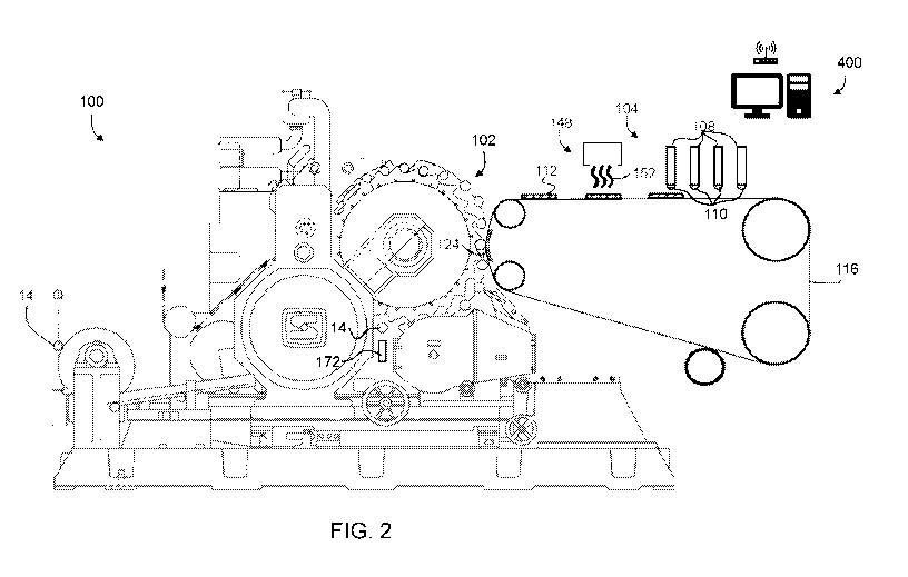
[0026] FIG. 2 is a side view of a decorating apparatus;
[0027] FIG. 3 is a close up view of a printing site of a decorating
apparatus;
[0028] FIG. 4 is a view of a substrate having a flush cycle ink pattern
deposited on a
surface thereof;
[0029] FIG. 5 is a top view of a transfer medium with a flush cycle ink
pattern deposited
within gaps on an upper surface thereof;
[0030] FIG. 6 is a side view of a sacrificial container component with a
flush cycle ink
pattern deposited on a side wall thereof;
[0031] FIG. 7 is perspective of an inspection station; and
[0032] FIG. 8 is an ejection module showing an ejection chute and a
sacrificial container
component processing therethrough.
DETAILED DESCRIPTION
[0033] While this invention is susceptible of embodiments in many different
forms, there
is shown in the drawings and will herein be described in detail preferred
embodiments of the
invention with the understanding that the present disclosure is to be
considered as an
exemplification of the principles of the invention and is not intended to
limit the broad aspect
of the invention to the embodiments illustrated.
[0034] A feature of this disclosure intentionally sacrifices one or more
container bodies
periodically at predetermined or random intervals to fully "flush" inkjet
printhead nozzles.
This feature includes the capability of automatically removing sacrificed
container
components from a production queue of container components. A benefit of the
ability to
eject these sacrificed container components from the process line is that
production does not
need to be stopped to maintain printhead nozzle stability.
CA 03136317 2021-10-06
WO 2020/210302 PCT/US2020/027193
7
[0035] This technology yields additional benefits. For example, the
interval of sacrificed
container components can be adjusted by a user as needed to maintain print
quality.
Alternatively, the interval can be adjusted programmatically via algorithm
based on ambient
temperature/humidity conditions, or programmatically based on the ink coverage
of the
customer print (if the ink coverage is low, sacrificial container bodies would
be needed more
often).
[0036] Embodiments of the present disclosure may be distinguished by a
flushing
interval. A flushing interval is a period between flushing cycles where a
flushing ink pattern
is deposited on a sacrificial container component. The period can be defined
manually by
operator intervention of automatically by time duration, a quantity or number
of decorated or
processed container components, ambient conditions, inkjet printhead use or a
combination
of these variables. The interval can be fixed in software routine. The
interval can be variable
and/or dependent upon one more operating conditions, such as ambient
temperature/humidity
(hotter/drier conditions require more flushing). The flushing interval may be
adjusted
(perhaps programmatically) based on the ink coverage of the customer job
(lower ink output
requires more flushing). Flushing may also be triggered on-demand by a vision-
inspection
camera system downstream in the manufacturing process from the decorator.
[0037] A procedure may be performed without operator involvement. In
conjunction
with an inspection system, for example, as described in PCT/US2017/033527,
which is
hereby incorporated by reference in its entirety as if fully set forth herein
and particularly for
the broad aspect of a decorator inspection system incorporated into the
container body
manufacturing process, the system as defined herein and the visual decoration
inspection
system are in communication via transmitted signals, wherein the vision system
can
communicate to a printer/decorator to command the printer/decorator to print
one or more
sacrificial container components once print quality is detected to be in a
degraded state or out
of manufacturing tolerance.
[0038] An advantage of the present disclosure is improved efficiency by
decreasing
downtime, in a decorating system as described, a printhead cleaning must be
performed every
60-90 minutes. Six printhead cleanings per 8-hour shift (6 x 15 minutes) could
be 90 minutes
of downtime, or the potential loss of (90 x 140 CPM) 12,600 container
components. Even if
a container component is sacrificed every single minute of an 8 hour
production cycle (a rate
which should not be required with UV Inks, but could be required with water-
based inks),
only 480 container components per 8-hour shift would be sacrificed.
CA 03136317 2021-10-06
WO 2020/210302 PCT/US2020/027193
8
[0039] Referring to FIG. 1, a container decorating system may be a
subsystem within a
container component manufacturing process 10. A schematic of a typical process
10 for
producing container bodies 14 is illustrated. However, the systems and
subsystems described
herein can be readily applied to the production of other container components,
such as lids,
tabs, etc.
A Decorating Station
[0040] Referring to FIGS. 2 and 3, a decorating station preferably
comprises a decorating
apparatus 100 which delivers one or more art graphics to a plurality of
container components
14 in a manufacturing queue 22. The decorating apparatus 100 has a container
component
handling module 102 which delivers container components 14 to a printing site
124, a supply
of ink in an inker unit 104 comprising one or more colored inks, and one or
more inkjet
printheads 108 which have one or more nozzles through which the one or more
colored inks
are delivered. A flush cycle controller which may be housed on a computer 400
activates a
flush cycle of the one or more nozzles to deposit a flush cycle ink pattern
109 on a substrate
25 to restore a meniscus 110 of the one or more nozzles. The flush cycle
controller can be
included in the decorating station or part of a computer network as described
below. Thus,
the flush cycle controller maybe external or internal to the decorator, for
example within a
hardware of the decorator itself without any need for an external controller.
In other words,
as used herein, flush cycle controller is not necessarily an external element
and should not be
considered as such unless specifically so descriptively modified.
[0041] The container component handling module 102 features an indexer
which
transports container components 14 one-by-one to the printing site 124 where
ink is
transferred from an image transfer medium, such as a continuous belt 116 as
illustrated in
FIG. 2, a segmented transfer blanket as illustrated in FIG. 5, or any of the
more traditional
offset type transfer systems known in the art which generally employ a
plurality of transfer
blankets attached to a rotation transfer drum. In any case, the decorating
apparatus 100
comprises an inkjet printhead 108.
[0042] The decorating apparatus 100 has an inker unit 104 comprising a
plurality of
printheads 108. The inkjet printheads 108 deliver a volume of ink 112 via the
nozzles in a
desired pattern to the image transfer belt 116. Each printhead 108 delivers a
quantity of ink
112 to the transfer medium to produce a desired pattern of ink 112 in a
desired color,
preferably multiple colors.
CA 03136317 2021-10-06
WO 2020/210302 PCT/US2020/027193
9
[0043] The image transfer medium transports a pattern of ink 112 received
from the
inkjet printheads 108 to a printing site 124 where engagement (i.e. contact)
between the
container component 14 and the image transfer medium transfers the ink 112 to
impart the art
graphic directly on the container component 14.
[0044] The ink 112 pattern is transferred to the container component 14 by
compressive
force on the beverage container component and the image transfer belt 116.
More
specifically, a printing surface 132 carrying the desired pattern of ink 112
is forced against
one of the plurality of container components 14 supported by an impression
member as the
container component 14 rotates about a center axis of the impression member.
[0045] The decorating apparatus 100 may be outfitted with an ink curing
station 148.
This ink curing station 148 may comprise a source of heat 152. The heat 152
pre-cures the
ink 112 on the image transfer medium to minimize wet on container component 14
issues.
This creates a more stable ink 112 as an ink image or pattern prior to
transferring the ink 112
to the container component 14. Due to printing to the transfer medium and pre-
curing,
multiple color dots can be combined to generate a larger color pantone options
with base
colors.
[0046] The decorating apparatus 100 allows a one-touch application of an
entire art
graphic. Continuous application of ink 112 onto the transfer medium allows for
the limiting
speed factor of the printhead 108 to be maximized. Printhead 108 jetting onto
a receptive
transfer medium in a repeatable position/condition medium as opposed to a
moving round
container component with a variable surface leads to consistency and speed.
[0047] It is further contemplated that the decorating apparatus 100 can be
configured to
directly deposit an art graphic on a container component 14 without first
depositing the ink
112 on a transfer medium.
[0048] The decorating apparatus 100 may deposit a flush cycle ink patter
109 into the
manufacturing run during a print run of consecutively decorated container
components 14.
One purpose of the flush cycle ink pattern 109 is to jet a substantial volume
of ink 112
(compared to the ink jetted during a typical print). By jetting a
predetermined volume of ink
112 in a short time interval, each inkjet printhead 108 nozzle becomes
sufficiently "flushed"
and an ink meniscus is reformed. This meniscus 110 is critical to the
performance of inkjet
printheads 108.
[0049] As an example, the flush cycle may deposit a flush cycle ink pattern
109 where
0.5 inches of ink 112 of each color is jetted at 100% density. For example,
referring to FIG.
4, the 0.5 inches is an indication of a width w of the rectangle or bar of the
flush cycle ink
CA 03136317 2021-10-06
WO 2020/210302 PCT/US2020/027193
pattern 109 on a given substrate. This measurement also refers to a time
variable, i.e. a cycle.
Functionally, the flush cycle relates to an amount of ink 0.5 inches of
printing, in a typical
case might be 2mL per color. One hundred percent density jetting refers to the
printhead
jetting the largest drops it can (varies by printhead model) over whatever
time duration or
interval an operator or designer asks/requests/demands/pre-programs.
Basically, in the
illustrated embodiments, solid rectangles/bars are printed with using as much
ink as the
apparatus, including, primarily, the printheads, is capable of depositing on a
substrate (i.e. a
transfer medium, a target to be printed, can component, etc.). "Each color" as
used herein
refers to the exact color of ink contained within each printhead 108. This is
typically cyan,
magenta, yellow, and key (typically black) ("CMYK"); however, "each color" may
also
include other colors, such as orange and green, for extended gamut printing,
or even a
specific spot color.
[0050] This flush cycle is necessary because under typical use, an inkjet-
type decorating
apparatus 100 may not utilize all the nozzles of each color. For example, if
an upper half of a
finished container art graphic does not employ black ink, then the black
printhead nozzles in
that area would not jet any ink. Given that one aspect of digital decoration
is to print variable
data (i.e. different art graphics in a single manufacturing run), if a
container component 14 art
graphic comes along later in the manufacturing queue 22 or print run which
requires black
ink in that area, the black inkjet nozzles might have a dried or broken
meniscus 110 by the
time a container component 14 requiring the design arrives at a printing site.
Thus, when that
container component 14 arrives at the printing site 124, and it is finally
time to print, the print
quality would not be acceptable or out of the customer's specification or the
manufacturing
tolerance.
[0051] Thus, the number of nozzles employed during any one manufacturing
run or print
run can vary, depending on the art graphics delivered during the run. In some
manufacturing
runs, one or more of the nozzles may be used less than the others or not at
all. To retain their
ability to function, these nozzles must jet ink at some minimum interval to
maintain meniscus
110 stability. In most applications, this is done by printing a flush cycle
ink pattern 109,
typically solid bar(s) 500 of ink at some point. This flush cycle ink pattern
109 printing
cannot be done within an indexed container printer without impacting an art
graphic
deposited on the container component 14.
[0052] Accordingly, a feature of the present disclosure periodically
(predetermined,
randomly, and/or upon receipt of an alert) and intentionally sacrifices one or
more container
components 14, as needed, to "flush" the printhead nozzles fully. This feature
may include
CA 03136317 2021-10-06
WO 2020/210302 PCT/US2020/027193
11
removing or ejecting sacrificial container components 26 from the
manufacturing queue 22.
Thus, production and decoration of container components 14 does not need to be
stopped in
order to maintain printhead nozzle stability.
[0053] Many approaches can be taken to controlling flush cycle intervals
(i.e. a time
period between flush cycles). The flush cycle interval can be adjusted or
controlled manually
by an operator intervention as needed to maintain print quality, adjusted
programmatically,
e.g. by software subroutine, based on inspection evaluation an of art graphics
produced
during the manufacturing run, based measurements of atmospheric or ambient
conditions,
such as temperature, humidity, dew point, pressure, etc., and/or predetermined
based on the
ink coverage of the customer's desired art graphic print. If the ink coverage
needed to create
the art graphic is low, sacrificial container components 26 would be needed
more often.
Generally, flush cycle intervals vary by printhead and ink type.
[0054] In one embodiment, a flush cycle, wherein a volume of ink 112 must
be jetted
from a given printhead 108 every 30 seconds to avoid a meniscus break. A
meniscus 110 can
usually be recovered within as few as three jetting operations in a fraction
of a second.
[0055] Where several minutes, e.g. greater than 10, elapse without a
printhead 108 jetting
a volume of ink 112, a printhead nozzle meniscus 110 can break and also dry
while open.
This may require physical cleaning before the printhead 108 will jet again.
Addressing this
case by avoiding its occurrence is just one object of this disclosure.
[0056] By way of illustrative example, if a print or decorating run,
requires printing solid
red container components for a substantial period of time, e.g. an hour, it is
unlikely that
printheads 108 delivering black or cyan ink would be used much, if at all.
Those printheads
108 are likely to be completely dried out and require hand-cleaning before a
decorating run
requiring the decorating apparatus to print blue container components may
begin. This
disclosure addresses that situation by requiring a flush cycle and the
production of a
sacrificial container component 26.
[0057] Particular to the present disclosure, the decorating system utilizes
one or more
substrates 25, e.g. sacrificial container components 26, in order to print a
flush cycle ink
pattern 109 by one or more of the printheads 108. The flush cycle ink pattern
109 is designed
to be dynamically recognized by an ink detection sensor 172 which collects or
recognizes ink
data associated with the one or more colored inks delivered by the one or more
nozzles. This
can be accomplished by the ink detection sensor 172 being configured to
recognize a
dark/light/dark/light/dark/light/dark flush cycle ink pattern 109 as
illustrated in the figures.
The ink detection sensor 172 can be an element of the decorating station (as
shown in FIG. 2)
CA 03136317 2021-10-06
WO 2020/210302 PCT/US2020/027193
12
or in a separate inspection station as described below. It is further
contemplated that the eject
function can be electronically integrated such that a controller and/or
computer 400 can
directly signal the ejection of the sacrificial container 26 without detection
of the flush cycle
ink pattern 109 by tracking the sacrificial container 26 in the process.
[0058] The system is responsive to the ink data collected or recognized by
the ink
detection sensor 172. In the case where the ink detection sensor 172 detects a
flushing cycle
ink pattern 109, the substrate 25, in this case typically a sacrificial
container component 26,
can be ejected from the manufacturing queue 22. In this manner, the intended
design of the
normally printed container components 14 does not need to take into account
the needs of
printhead meniscus 110 stability in that design. In one embodiment, ejection
of one or more
sacrificial container components takes place on a track work.
[0059] The decorating station may have an ejection system as shown in FIG.
8. A
container component ejection sensor ensures that a container component having
a flush cycle
ink pattern 109 is ejected. An air knife may be provided to blow the container
component 26
into an eject chute 252. A control system flags a sacrificial container
component 26 as it
passes by the ink detection sensor 172. The sacrificial container component 26
is tracked
until it reaches the ejection chute 252 at an ejection position 216. When it
senses that the
sacrificial container component 26 is passing the eject chute, the air knife
248 blows the
sacrificial container component 26 into the eject chute 252.
[0060] It is contemplated that the ink 112 of the flushing cycle ink may be
deposited on a
substrate 25 other than a sacrificial container component 26. For example,
referring to FIGS.
1, 2, and 5, a decorating apparatus 100 may be outfitted with a transfer belt
116, such as a
non-segmented or segmented transfer belt 116 as illustrated. These belts 116
are fully
described in PCT/US2018/051717 and PCT/US2018/051719, which are hereby
incorporated
by reference as if fully set forth herein and for the particular purpose of
describing the
particular transfer belts 116 described therein.
[0061] Referring specifically to FIG. 5. a segmented image transfer blanket
116 has a
plurality of adjacent blanket segments 118 separated by gaps 121a-d. The gaps
121a-d may
be a recessed surface of the segmented image transfer blanket 116, at least
relative to printing
surfaces on the blanket segments 118. Each blanket segment 118 has a printing
surface
configured to accept the volume of ink 112 from the ink-jet printing heads 108
and transfer
the ink 112 to the container components. Thus, a segmented image transfer
blanket 116 may
have a gap 121a-d between adjacent blanket segments 118 which has a surface
height that is
recessed in relation to the printing surfaces of the adjacent blanket segments
118.
CA 03136317 2021-10-06
WO 2020/210302 PCT/US2020/027193
13
[0062] In the case of such a segmented belt 116, the ink 112 of the flush
cycle ink pattern
109 can be deposited between the blanket segments 118 within one or more of
the gaps 121a-
d.
[0063] Alternatively, a very thin plate can be configured to swing or be
transferred into a
position beneath the inkjet print heads 108 to deflect or "catch" ink droplets
or the flush cycle
ink pattern as they/it are/is jetted onto the plate. Another alternative
employs a fluid pressure.
Here, a source of a fluid pressure blows a gas, for example air, physically
blows the ink
droplets or ink for a flushing pattern delivered by the inkjet printheads 108
to the side via an
air knife wherein the ink is not deposited onto a container component. While
these
alternatives have advantages, neither of these alternatives enjoys, at least,
the cost and
logistical advantages of printing a sacrificial container component with the
flush cycle in
pattern.
An Inspection Station
[0064] The present system may incorporate an inspection station 200 such as
those
described in PCT/US2017/033527, which is hereby incorporated by reference as
if fully set
forth herein. Particular to the present disclosure, the inspection station 200
can be used to
control, determine, activate, etc. the flushing cycle and or flushing cycle
interval, the
sacrificial container component(s) 26 and the flushing cycle ink pattern 109.
[0065] The inspection station 200 is generally downstream in a container
component
manufacturing process 10 from the decorating station 100. In terms of process
steps, the
inspection station 200 is located after the decorating station 100 and
optionally post-
decoration oven station. Thus, in one example, the container component 14 may
be a
container body which has a cylindrical sidewall separating an open end from an
integral
closed end wherein a portion of the sidewall immediately adjacent the open end
has a
circumference that is substantially equal to the circumference of a portion of
the sidewall
adjacent the integral bottom portion.
[0066] It is contemplated that the inspection station 200 will be installed
as close to the
end of the decorating station 100 as possible, to minimize bad (i.e.
defective, sub-standard,
non-conforming) beverage container component production. By locating the
inspection
closer to the decorator, fewer "bad components" are produced prior to
discovering and
resolving the cause of the defects. This station 200 is primarily looking for
decoration
defects.
[0067] The inspection station 200 includes an ink detection sensor 204. The
ink detection
sensor can be an optical sensor, e.g. a camera or any other known and unknown
techniques,
CA 03136317 2021-10-06
WO 2020/210302 PCT/US2020/027193
14
including but not limited to UV and/or infrared inspection as well as other
non-optical related
measurements such as surface energy.
[0068] For the present disclosure, the purpose of the inspection station
200 is to identify
when a flushing cycle of the printhead nozzles is necessary. This can be
accomplished by
identifying characteristics of ink deposited on one or more container
components that are
associated with meniscus instability. There are two main categories of
meniscus failure.
[0069] A first is jetout. This occurs when printhead nozzle is not jetting
ink at all due to
a completely broken meniscus. This commonly presents itself as a very narrow
stripe of
missing color in the finished design, i.e. a decorated container component.
[0070] A second category is deviation. Deviation occurs when a printhead
nozzle is
jetting ink, but not directly downward. Here, the ink drops typically jet at
an angle and may
contain less or more ink than they should. This is typically caused by a
partially formed
meniscus or partially blocked nozzle. Deviation is the more difficult of the
two categories to
detect, it generally presents itself as a dark stripe on the finished design.
[0071] Both these situations are best addressed by flooding a nozzle with
ink during a
flush cycle with the intent of clearing any blockage and reforming the
meniscus. The sooner
this operation can be done after the failure is identified, the better. This
is a primary driver
behind the present disclosure, i.e. providing a capability to perform one or
more flushing
cycles without stopping the manufacturing process or waiting for a maintenance
window (an
open time period in which maintenance can be performed on the
manufacturing/decorating
apparatus).
[0072] In one embodiment, ejection of one or more sacrificial container
components
takes place on a track work. A container component ejection sensor 250 ensures
that a
container component 14 having a flush cycle ink pattern 109 is ejected. An air
knife 248 may
be provided to blow the container component 26 into a eject chute 252. A
control system
flags a sacrificial container component 26 as it passes by the ink detection
sensor 204. The
sacrificial container component 26 is tracked until it reaches the ejection
chute 252 at an
ejection position 216. When it senses that the sacrificial container component
26 is passing
the eject chute 252, the air knife 248 blows the sacrificial container
component 14 into the
eject chute 252. (See FIG. 8).
[0073] It should be understood that the inspection station 200 is fully
programmable.
Furthermore, a controller is capable of synchronizing the movement of an
inspection station
container component handling module with the overall manufacturing process. It
generally
follows that a programmable controller which may be housed on a computer 400
and can be
CA 03136317 2021-10-06
WO 2020/210302 PCT/US2020/027193
used to control the timing of the inspection station 200. The computer 400 may
have a
software routine store on a memory wherein the software routine controls
movement of the
inspection station and the decorating station. The computer 400 can also be
used to
determine the attributes of the flush cycle, including flush cycle interval,
extent and identity
of the nozzles flushed, volume of ink flushed, the shape, size, location, etc.
flush cycle ink
pattern.
[0074] It should be clearly understood that the colors or the printhead
nozzles to flush can
be individually chosen programmatically. While there is no true detriment to
extra flushing,
such extraneous flushing unnecessarily expends ink with each flush. By way of
an
illustrative example, if magenta is the only misbehaving or malfunctioning
color, one would
only want to flush magenta in order to not waste the other inks. This behavior
would be
configurable via a software routine stored on the computer 400.
[0075] As shown, the inspection station 200 may be outfitted with an
ejection system.
The ejection system includes an ejector positioned between an index path and
the
manufacturing queue 22 for culling the sacrificial container component 26 from
the
manufacturing stream of sequentially processed container components prior to
transferring
the container component to a subsequent process. The ejector may be a
mechanical spring-
loaded kick-out, a mechanical arm, pendulum, plunger, piston, plate, or
grasping apparatus,
or other mechanical system, but is preferably a blow-off nozzle, such as an
air knife 248,
including a source of fluid pressure in which activation of same is either
manually controlled
or, more preferably controlled by a signal originating from a software routine
stored in the
memory on a computer 400 which compares the results of an evaluation
corresponding to the
ink data collected by the ink detection sensor to a quality standard preset by
the manufacturer.
If, upon comparison of the inspected container component 14 to the quality
standard, the
container component 14 is deemed to fail the quality standard, the fluid
pressure is activated
and delivered through the blow-off nozzle to the container component which
thrusts the
container component from the indexer to a reject chute and into a waste area,
such as waste
bin. This same evaluation can be used to initiate one or more flush cycles at
the decorating
station.
[0076] The ejector is located between an index path of the inspection
station 200 and the
manufacturing queue 22. That is, the ejector is capable of removing a
defective container
component or sacrificial container component 26 prior to subsequent steps in
the
manufacturing process 100.
CA 03136317 2021-10-06
WO 2020/210302 PCT/US2020/027193
16
A Computer
[0077] A computer or computers 400 may be included in the system. For
purposes of this
description, one or more computers are referred to in the singular, but it
should be understood
that the decorating station and the inspection station 200 may have computers
devoted solely
to the individual process, and these computers can function as single network
wherein signals
generated and received by and between the processes can be used to effect
changes in the
processes or to trigger certain processes or subroutines. In one particular
example, the
computer can be used to control a flushing cycle of one or more inkjet
printheads 108 on the
decorating apparatus 100. Thus, it follows that a computer 400 has a software
stored in a
memory.
[0078] One computer 400 has a software associated with the inspection
station 200. The
software controls the evaluation of the quality of the art graphics and flush
cycle ink pattern
109 by comparing ink data of an actual pattern of ink against a quality
standard, such as a
customer specification or manufacturing tolerance. For the purposes of this
disclosure, the
software compares colors and printed patterns to determine when a flushing
cycle is
necessary and which printhead nozzles must be flushed and to what extent. When
an ink-
related anomaly is detected, either a signal is sent directly to, or generated
within, the
decorating station to cause one or more flush cycles using a software or a
signal is sent to an
operator to manually cause the necessary flush cycle(s).
[0079] In an embodiment, a software on the computer 400 may be used to
detect color
hue on the container components 14, for example wavelength, saturation also
called
"chroma", and brightness also called "luminance" or "value," which is the
shade (darkness)
or tint (lightness) of a color. This software can also close the loop and be
used to
automatically adjust the decorating station to obtain the correct hue. The
software would
inspect the container components after decoration via optical scanner and look
for
representative signs of meniscus instability. If such instability is found,
the software would
be able to trigger the flushing process for the affected color plane(s)
Illustrative Examples
[0080] Methods of the present disclosure trade a small amount of input
material
(container components) to maintain the health of the most critical asset to a
digital decoration
system, the decorating apparatus. The number of sacrificed container
components is
customizable by an operator, but a reasonable expected trade-off is
sacrificing 1 container
component every ¨5 minutes in order to extend the printhead cleaning interval
by 2-8 hours.
This takes an offline cleaning procedure, with an estimated time of 10-30
minutes, and
CA 03136317 2021-10-06
WO 2020/210302 PCT/US2020/027193
17
replaces it with an online flushing procedure which sacrifices a single
container component
every 5 minutes.
[0081] In one embodiment, container component inspection is performed
manually by an
operator visually in-hand, this allows the inspection to be performed under a
minimal time
duration which prevents container components being produced with art graphics
that are
outside the manufacturing tolerance for same. In an embodiment where
inspection is
performed automatically by an ink detection sensor 172,204, the method removes
the
sacrificial container component 26 from the manufacturing queue 22 before
additional
manufacturing processes are wastefully performed on the sacrificial container
component 26.
[0082] In one embodiment, an ink detection sensor 172,204 can be used and
directed at a
specific portion of the container component 14 to detect print and/or color
quality. An ink
detection sensor 172 can be included on the decorating station 100. An ink
detection sensor
172,204 can send a signal to the computer 400 where an evaluation of the
collected ink data
is performed to determine whether a flushing cycle is necessary.
[0083] In one embodiment, a sacrificial container component 26 is removed
from the
manufacturing queue 22 immediately, or substantially immediately, after the
decorating of
the container component with a flush cycle ink pattern 109.
[0084] In one embodiment, a printed flush cycle ink pattern 109 is adapted,
as in shaped
and located, to be recognized by an ink detection sensor 172,204, such as an
optical sensor.
[0085] In one embodiment, any or all of the sensors 172,204,250 are optical
sensors.
[0086] In one embodiment, any or all of the sensors 172,204,250 are light
sensors.
[0087] In one embodiment, any or all of the sensors 172,204,250 are energy
sensors.
[0088] In one embodiment, a sacrificial container component 14 is
recognized by the ink
detection sensor 172,204 and removed from the manufacturing queue 22
automatically.
[0089] In one embodiment, the decorating station 100 is in communication
with a
downstream device which ejects a sacrificial container component 26 from the
manufacturing
queue 22. It is important for the sacrificial container component 26 to be
removed from
manufacturing queue 26. Otherwise, the sacrificial container component 26
could be finally
palletized with a customer's container component order.
[0090] In one embodiment, an inspection station 200 performs an evaluation
of all of the
colors on a decorated beverage container component 14 and a software on the
computer 400
quantitatively and/or qualitatively analyzes the colors on the container
components 14 and
automatically adjusts the decorating station to order a flush cycle. For
example, a camera and
CA 03136317 2021-10-06
WO 2020/210302 PCT/US2020/027193
18
software may determine that the color red is light 3%, and automatically
adjust the decorating
station.
[0091] In one embodiment, the flushing interval is determined as a function
of results
from a visual or optical inspection. For example, an inspection result
indicates that nozzle
flushing is necessary. The flush cycle interval can be varied such that
several consecutive
container components in a manufacturing queue 22 become sacrificial container
components
26 by receiving one or more flush cycle ink patterns 109.
[0092] While the specific embodiments have been illustrated and described,
numerous
modifications come to mind without significantly departing from the spirit of
the invention,
and the scope of protection is only limited by the scope of the accompanying
Claims.