Note: Descriptions are shown in the official language in which they were submitted.
Ref. No. 68839-CA
SYSTEMS AND METHODS TO MITIGATE FUSION BETWEEN A WIRE
ELECTRODE AND A WELDING TORCH
CROSS-REFERENCE TO RELATED APPLICATIONS
[0001] This application hereby claims priority to and the benefit of U.S.
Provisional
Application Ser. No. 63/109,617, entitled "Systems and Methods to Mitigate
Fusion Between a
Wire Electrode and a Welding Torch," filed November 4, 2020, and U.S. Non-
Provisional Utility
Application Ser. No. 17/506,818 filed October 21, 2021, and entitled the same.
BACKGROUND
[0001] One of the first steps of a welding process is establishing an
electrical arc between a
welding torch and a workpiece. Some arc welding systems use wire electrodes
fed to the welding
torch to establish the electrical arc. Establishing and maintaining the
electrical arc with the wire
electrode is easier if the wire electrode is free of welding residue or
unwanted contact with the
welding torch during performance of the weld. For example, during some welding
processes, the
wire electrode may "stick" or fuse to a contact tip, creating issues during
performance of the weld.
[0002] Limitations and disadvantages of conventional and traditional
approaches will become
apparent to one of skill in the art, through comparison of such systems with
the present disclosure
as set forth in the remainder of the present application with reference to the
drawings.
BRIEF SUMMARY
[0003] The present disclosure is directed to systems and methods for
mitigating the negative
effects of a wire fusing to a contact tip during a welding process,
substantially as illustrated by
and/or described in connection with at least one of the figures, and as set
forth more completely in
the claims.
[0003a] In a broad aspect, provided is a welding system that includes a
welding power supply
to provide power to a welding torch for establishing an electrical arc between
a metal cored
welding wire and a workpiece to perform a weld, and control circuitry
configured to control the
1
Date recue/date received 2021-10-28
Ref. No. 68839-CA
power supply to output a waveform having a peak phase and a background phase.
The control
circuitry is configure to command the power supply to output a first pulse at
a first current level
above a threshold current level required to transfer a ball of molten welding
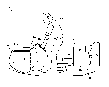
wire in the peak phase,
and command the power supply to output a second pulse at a second current
level below the
threshold current level in the background phase. The second current level is
sufficient to dislodge
a spot weld between the welding wire and the welding torch and not sufficient
to transfer a ball of
molten welding wire.
10003b] In another aspect, provided is a welding system that includes a
welding power supply
to provide power to a welding torch for establishing an electrical arc between
the welding wire
and a workpiece to perform a weld, and control circuitry configured to control
the power supply
to output a waveform having a peak phase and a background phase. The waveform
has a series of
pulses alternating between a first pulse at a first current level during the
peak phase, and a second
pulse at a second current level during the background phase. The control
circuitry is configured
to command the power supply to output a first pulse at a first current level
above a threshold current
level required to transfer a ball of molten welding wire in the peak phase,
command the power
supply to output a background current at a background current level following
the first pulse, and
command the power supply to output a second pulse at a second current level
greater than the
background current level and below the threshold current level during the
background phase. The
second current level is sufficient to dislodge a spot weld between the welding
wire and the welding
torch and not sufficient to transfer a ball of molten welding wire.
[0003c] In a further aspect, provided is a welding system that includes a
welding power supply
to provide power to a welding torch for establishing an electrical arc between
the welding wire
and a workpiece to perform a weld, and control circuitry configured to control
the power supply
to output a waveform having a peak phase and a background phase. The waveform
has a series of
pulses alternating between a first pulse at a first current level during the
peak phase, and a second
pulse at a second current level during the background phase. The control
circuitry is configured
to command the power supply to output a first pulse at a first current level
above a threshold current
level required to transfer a ball of molten welding wire in the peak phase,
command the power
supply to output a background current at a background current level following
the first pulse,
2
Date recue/date received 2021-10-28
Ref. No. 68839-CA
monitor one or more welding parameters, detect a fusion event based on the one
or more welding
parameters, and command the power supply to output a second pulse at a second
current level
greater than the background current level and below the threshold current
level during the
background phase in response to detection of the fusion event. The second
current level is
sufficient to dislodge a spot weld created by the fusion event between the
welding wire and the
welding torch and not sufficient to transfer a ball of molten welding wire.
[0004] These and other advantages, aspects and novel features of the
present disclosure, as
well as details of an illustrated example thereof, will be more fully
understood from the following
description and drawings.
BRIEF DESCRIPTION OF THE DRAWINGS
[0005] FIG. 1 is a perspective view of an operator using an example welding
system, in
accordance with aspects of this disclosure.
[0006] FIG. 2 is a block diagram illustrating components of the example
welding system of
FIG. 1, in accordance with aspects of this disclosure.
[0007] FIGS. 3A and 3B are graphs illustrating an example welding program,
in accordance
with aspects of this disclosure.
[0008] FIG. 4 is a graph illustrating an example welding program,
accordance with aspects of
this disclosure.
[0009] FIGS. 5A and 5B are graphs illustrating a detailed view of the graph
of FIG. 4, in
accordance with aspects of this disclosure.
[0010] FIG. 6 is a diagrammatic illustration of an example welding process
aligned with an
example graphical representation of waveforms, in accordance with aspects of
this disclosure.
[0011] FIGS. 7A and 7B are flowcharts illustrating example welding
programs, in accordance
with aspects of this disclosure.
[0012] The figures are not necessarily to scale. Where appropriate, the
same or similar
reference numerals are used in the figures to refer to similar or identical
elements.
3
Date recue/date received 2021-10-28
Ref. No. 68839-CA
DETAILED DESCRIPTION
[0013] Systems and methods for mitigating the negative effects of a wire
fusing to a contact
tip during a welding process are disclosed. In particular, the disclosed
systems and methods
address issues associated with welding with cored wires, although the
principles may be applicable
for a variety of wire types or welding processes where wire "sticking" issues
exist (e.g., wire
materials with a low melting point and high surface resistance; metal cored
wires; stainless steel
wires, etc.). For example, in certain processes, a welding wire may "stick" or
fuse to a contact tip,
creating issues with the advancing welding wire and subsequent transfer of a
molten metal droplet.
To mitigate the negative effects of a wire fusing to a contact tip during a
welding process, the
system is configured to command a pulse with a relatively low amount of
current to dislodge the
fused welding wire from the contact tip.
[0014] The disclosed systems and methods are configured to generate
waveforms with a series
of pulses to reduce the occurrence of a spot weld or fusion event between the
welding wire and a
welding torch (e.g., a contact tip), in particular, following a peak pulse of
current forcing a ball of
molten wire toward a workpiece. In some examples, the duration, severity,
size, and thereby
impact on the welding process, can be reduced or eliminated by adding another,
relatively small
pulse of current to break fused portion of the wire loose from the contact
tip.
[0015] Cored wire, also referred to as metal-cored wire, employs an
external sheath to encase
powdered metals. The sheath makes electrical contact with a contact tip of a
welding torch,
through which a substantial amount of current flows from the contact tip to a
workpiece to form a
weld. For instance, welding currents can range from below 350 to over 550
Amps. Although the
contact tip has a relatively large surface area, the point of contact with the
wire is relatively small
(e.g., with an area of 0.2 mm2 or less). The transfer of high current and
energy tends to generate a
hot spot on the wire in a type of fusion event. For example, the hot spot can,
and often does, freeze
and/or solidify (e.g., fuse) as the melting metallic interface between a
welding wire and a contact
tip cools and creates a bond, creating a spot weld inside the contact tip and
causing the wire to
temporarily stop feeding.
4
Date recue/date received 2021-10-28
Ref. No. 68839-CA
[0016] The wire may eventually break free from the contact tip (e.g., in
response to a force
from a wire feeder to drive the wire). For instance, the feeder may be
continuously feeding the
wire until the push force is able to break the fusion point between the wire
and the contact tip.
However, by the time the spot weld breaks freeing up the wire, a large spring
force has been built-
up in the wire, which may cause the wire to rapidly advance from the contact
tip at a wire feed rate
several times greater than a commanded wire feed rate. As a result, the wire
is thrust into the weld
puddle causing a hard short. Further, in order to clear the hard short created
at the weld puddle,
additional current must be added, creating another hot spot, which further
exacerbates the situation.
[0017] The disclosed systems and methods provide significant improvements
in welding of
cored wires, although the techniques disclosed herein may be applicable for
any wire and/or
welding process where spot welds or fusion events occur. By mitigation of the
effects of such spot
welds or fusion events (e.g., at an interface between the welding wire and an
internal surface of
the contact tip), a more consistent, stable and higher quality molten metal
droplet transfer is
achieved.
[0018] In some example systems, wire sticking to the contact tip is
mitigated by slowing down
the ramp rate from the peak current level to the background current level.
This technique provides
positive outcomes for relatively faster wire feed speeds. However, this
technique may result in
degraded performance at lower wire feed speed.
[0019] In some example systems, a narrow peak current pulse with a
relatively steep up-and-
down ramp rate provides better outcomes in terms of molten metal transfer when
using relatively
low wire feed speeds.
[0020] In some example systems, low amounts of energy added during low peak
pulses (while
welding with a low wire feed speed), and a corresponding slow transition from
peak current to
background current (e.g., with a long up-and-down ramp rate) would cause one
or more of: too
much energy being added to the weld; a reduction in the pinch current applied
to the ball of molten
welding wire on the end of the wire; an unnecessary high arc voltage and/or a
spike in arc voltage;
and/or the arc length to be too long.
Date recue/date received 2021-10-28
Ref. No. 68839-CA
[0021] At higher wire feed speeds, the amount of time needed to return to a
background current
level to prevent the wire from fusing with the contact tip increases. The
reason being that a high
amount of peak energy allows for manipulation of the waveform (e.g., ramp
rates, peak or
background current levels, etc.), while maintaining a good transfer of the
molten ball of wire to
the puddle.
[0022] At lower wire feed speeds fusion events such as spot welds are more
challenging to
mitigate. In order to reduce the amount of time the conditions exist to create
a spot weld or fusion
event between the welding wire and the contact tip, a partial second peak is
provided to reheat the
location of the fusion event (e.g., a spot weld of the welding wire to contact
tip) and break it free,
without adding energy at a level sufficient to create a second spot weld
(and/or generate a ball of
molten welding wire).
[0023] As a result, minimizing the effects on the welding process from spot
welds and/or
fusion events could be achieved. Thus, providing a relatively small amount of
energy (e.g., a small
partial peak) to heat the spot weld forces the fused material to dislodge, the
welding wire thereby
breaking free of the contact tip before much of a spring force has built up in
the wire (due to the
force provided from a wire feeder). By implementing these techniques, hard
shorts caused by
sudden spikes in wire feed speed advancing the welding wire into the puddle
were avoided.
[0024] In additional or alternative examples, a harmonic or oscillator
could be imposed over
the waveform during the welding operation to constantly or periodically add
small bursts of energy
to clear any fusion point between the wire and the contact tip. The
oscillation could be any suitable
waveform, which may be synchronized or non-synchronized with the pulse
waveform. The small
bursts of energy would be provided with a current level below threshold
current level required to
transfer a ball of molten welding wire.
[0025] Advantageously, application of the disclosed systems and methods
reduces sticking
effects of cored wire and improves the core wire droplet transfer.
Advantageously, application of
the disclosed double pulse waveform allows for the background current to be
reduced to a minimal
amount (e.g., between 20-30 amperes) without extinguishing the arc. Then the
peak current can be
used more effectively to melt the wire and transfer the ball or droplet of
molten welding wire.
6
Date recue/date received 2021-10-28
Ref. No. 68839-CA
[0026] In disclosed examples, a welding system, includes a welding power
supply to provide
power to a welding torch for establishing an electrical arc between a metal
cored welding wire and
a workpiece to perform a weld. Control circuitry is configured to control the
power supply to
output current as a waveform having a peak phase and a background phase. For
example, the
control circuitry commands the power supply to output a first pulse at a first
current level above a
threshold current level required to transfer a ball of molten welding wire in
the peak phase, and
commands the power supply to output a second pulse at a second current level
below the threshold
current level in the background phase, wherein the second current level is
sufficient to dislodge a
spot weld between the welding wire and the welding torch and not sufficient to
transfer a ball of
molten welding wire.
[0027] In some examples, the ball of molten welding wire is deposited onto
a workpiece during
the background phase. In examples, the second current level is greater than a
background current
level. In some examples, the peak phase and the background phase are applied
in a cyclic pattern
during performance of the weld.
[0028] In some examples, the control circuitry is further configured to
command the second
pulse at an approximate mid-point between two pulses output at the first
current level. In
examples, the control circuitry is further configured to command the second
pulse between 0.3 and
2.0 ms after the first pulse.
[0029] In some examples, the welding wire is commanded to advance at a
speed between 100
and 400 inches per minute. In examples, the threshold current level is between
100-300 amperes.
In examples, the second current level is equal to or less than half of the
first current level.
[0030] In some examples, the waveform further comprises one or more
intermediate phases
between the first pulse and the second pulse or between the second pulse and
another pulse having
the first current level. In some examples, the one or more intermediate phases
comprises one or
more knee phases, the control circuity further configured to control the power
supply to command
a current output at a level greater than the background current and below the
second current level
during the one or more knee phases.
7
Date recue/date received 2021-10-28
Ref. No. 68839-CA
[0031] In disclosed examples, a welding system, includes a welding power
supply to provide
power to a welding torch for establishing an electrical arc between the
welding wire and a
workpiece to perform a weld. Control circuitry is configured to control the
power supply to output
current as a waveform having a peak phase and a background phase, the waveform
having a series
of pulses alternating between a first pulse at a first current level during
the peak phase, and a
second pulse at a second current level during the background phase. The
control circuitry is
configured to command the power supply to output a first pulse at a first
current level above a
threshold current level required to transfer a ball of molten welding wire in
the peak phase,
command the power supply to output a background current at a background
current level following
the first pulse, and command the power supply to output a second pulse at a
second current level
greater than the background current level and below the threshold current
level during the
background phase, wherein the second current level is sufficient to dislodge a
spot weld between
the welding wire and the welding torch and not sufficient to transfer a ball
of molten welding wire.
[0032] In examples, the welding wire is a solid wire. In some examples, the
welding wire is
aluminum, steel, or an alloy. In examples, the first pulse forces transfer of
the ball of the welding
wire onto the workpiece.
[0033] In some examples, the control circuitry is further configured to
command the power
supply to transition from the background phase to the peak phase by commanding
another pulse
at the first current level after the second pulse.
[0034] In some examples, one or more sensors to measure one or more welding
parameters
including voltage, wire feed speed, or temperature. In some examples, the
control circuitry is
further configured to monitor the welding parameters to determine frequency or
severity of the
spot weld, and adjust one of duration or current level of the second or the
first pulse in response.
[0035] In examples, the welding process is current controlled.
[0036] In some examples, the further comprising a wire feeder configured to
advance the
welding wire to the workpiece at one or more wire feed speeds. In examples,
the welding wire is
commanded to advance at a speed between 100 and 500 inches per minute. In
examples, the
8
Date recue/date received 2021-10-28
Ref. No. 68839-CA
control circuitry is further configured to command the wire feeder to advance
the welding wire at
a constant wire feed speed during the arc phase and the background phase.
[0037] In examples, the first and second pulses are commanded with a common
ramp rate. In
some examples, the first and second pulses are commanded with different ramp
rates. In some
examples, the control circuitry is further configured to control the power
supply to output the first
pulse to achieve a first peak current at a first current ramp rate based on a
first wire feed speed. In
some examples, the control circuitry is further configured to control the
power supply to output
the first pulse to achieve a first peak current at a second current ramp rate
based on a second wire
feed speed.
[0038] In disclosed examples, a welding system includes a welding power
supply to provide
power to a welding torch for establishing an electrical arc between the
welding wire and a
workpiece to perform a weld. Control circuitry is configured to control the
power supply to output
a waveform having a peak phase and a background phase, the waveform having a
series of pulses
alternating between a first pulse at a first current level during the peak
phase, and a second pulse
at a second current level during the background phase. The control circuitry
is configured to
command the power supply to output a first pulse at a first current level
above a threshold current
level required to transfer a ball of molten welding wire in the peak phase,
command the power
supply to output a background current at a background current level following
the first pulse,
monitor one or more welding parameters, detect a fusion event based on the one
or more welding
parameters, and command the power supply to output a second pulse at a second
current level
greater than the background current level and below the threshold current
level during the
background phase in response to detection of the fusion event, wherein the
second current level is
sufficient to dislodge a spot weld created by the fusion event between the
welding wire and the
welding torch and not sufficient to transfer a ball of molten welding wire.
[0039] As used herein, the terms "first" and "second" may be used to
enumerate different
components or elements of the same type, and do not necessarily imply any
particular order.
[0040] The term "welding-type system," as used herein, includes any device
capable of
supplying power suitable for welding, plasma cutting, induction heating,
Carbon Arc Cutting-Air
9
Date recue/date received 2021-10-28
Ref. No. 68839-CA
(e.g., CAC-A), and/or hot wire welding/preheating (including laser welding and
laser cladding),
including inverters, converters, choppers, resonant power supplies, quasi-
resonant power supplies,
etc., as well as control circuitry and other ancillary circuitry associated
therewith.
[0041] As used herein, the term "welding power" or "welding-type power"
refers to power
suitable for welding, plasma cutting, induction heating, CAC-A and/or hot wire
welding/preheating (including laser welding and laser cladding). As used
herein, the term
"welding-type power supply" and/or "power supply" refers to any device capable
of, when power
is applied thereto, supplying welding, plasma cutting, induction heating, CAC-
A and/or hot wire
welding/preheating (including laser welding and laser cladding) power,
including but not limited
to inverters, converters, resonant power supplies, quasi-resonant power
supplies, and the like, as
well as control circuitry and other ancillary circuitry associated therewith.
[0042] As used herein, the term "torch," "welding torch," "welding tool" or
"welding-type
tool" refers to a device configured to be manipulated to perform a welding-
related task, and can
include a hand-held welding torch, robotic welding torch, gun, gouging tool,
cutting tool, or other
device used to create the welding arc.
[0043] As used herein, the term "welding mode," "welding process," "welding-
type process"
or "welding operation" refers to the type of process or output used, such as
current-controlled
(CC), voltage-controlled (CV), pulsed, gas metal arc welding (GMAW), flux-
cored arc welding
(FCAW), gas tungsten arc welding (GTAW, e.g., TIG), shielded metal arc welding
(SMAW),
spray, short circuit, CAC-A, gouging process, cutting process, and/or any
other type of welding
process.
[0044] As used herein, the term "welding program" or "weld program"
includes at least a set
of welding parameters for controlling a weld, which may include a weld
schedule, operational
settings, or others. A welding program may further include other software,
algorithms, processes,
or other logic to control one or more welding-type devices to perform a weld.
[0045] As used herein, "power conversion circuitry" and/or "power
conversion circuits" refer
to circuitry and/or electrical components that convert electrical power from
one or more first forms
(e.g., power output by a generator) to one or more second forms having any
combination of
Date recue/date received 2021-10-28
Ref. No. 68839-CA
voltage, current, frequency, and/or response characteristics. The power
conversion circuitry may
include safety circuitry, output selection circuitry, measurement and/or
control circuitry, and/or
any other circuits to provide appropriate features.
[0046] As used herein, the terms "coupled," "coupled to," and "coupled
with," each mean a
structural and/or electrical connection, whether attached, affixed, connected,
joined, fastened,
linked, and/or otherwise secured. As used herein, the term "attach" means to
affix, couple, connect,
join, fasten, link, and/or otherwise secure. As used herein, the term
"connect" means to attach,
affix, couple, join, fasten, link, and/or otherwise secure.
[0047] As used herein the terms "circuits" and "circuitry" refer to any
analog and/or digital
components, power and/or control elements, such as a microprocessor, digital
signal processor
(DSP), software, and the like, discrete and/or integrated components, or
portions and/or
combinations thereof, including physical electronic components (i.e.,
hardware) and any software
and/or firmware ("code") which may configure the hardware, be executed by the
hardware, and or
otherwise be associated with the hardware. As used herein, for example, a
particular processor and
memory may comprise a first "circuit" when executing a first one or more lines
of code and may
comprise a second "circuit" when executing a second one or more lines of code.
As utilized herein,
circuitry is "operable" and/or "configured" to perform a function whenever the
circuitry comprises
the necessary hardware and/or code (if any is necessary) to perform the
function, regardless of
whether performance of the function is disabled or enabled (e.g., by a user-
configurable setting,
factory trim, etc.).
[0048] The terms "control circuit," "control circuitry," and/or
"controller," as used herein, may
include digital and/or analog circuitry, discrete and/or integrated circuitry,
microprocessors, digital
signal processors (DSPs), and/or other logic circuitry, and/or associated
software, hardware, and/or
firmware. Control circuits or control circuitry may be located on one or more
circuit boards that
form part or all of a controller, and are used to control a welding process, a
device such as a power
source or wire feeder, and/or any other type of welding-related system.
[0049] As used herein, the term "processor" means processing devices,
apparatus, programs,
circuits, components, systems, and subsystems, whether implemented in
hardware, tangibly
11
Date recue/date received 2021-10-28
Ref. No. 68839-CA
embodied software, or both, and whether or not it is programmable. The term
"processor" as used
herein includes, but is not limited to, one or more computing devices,
hardwired circuits, signal-
modifying devices and systems, devices and machines for controlling systems,
central processing
units, programmable devices and systems, field-programmable gate arrays,
application-specific
integrated circuits, systems on a chip, systems comprising discrete elements
and/or circuits, state
machines, virtual machines, data processors, processing facilities, and
combinations of any of the
foregoing. The processor may be, for example, any type of general purpose
microprocessor or
microcontroller, a digital signal processing (DSP) processor, an application-
specific integrated
circuit (ASIC), a graphic processing unit (GPU), a reduced instruction set
computer (RISC)
processor with an advanced RISC machine (ARM) core, etc. The processor may be
coupled to,
and/or integrated with a memory device.
[0050] As used, herein, the term "memory" and/or "memory device" means
computer
hardware or circuitry to store information for use by a processor and/or other
digital device. The
memory and/or memory device can be any suitable type of computer memory or any
other type of
electronic storage medium, such as, for example, read-only memory (ROM),
random access
memory (RAM), cache memory, compact disc read-only memory (CDROM), electro-
optical
memory, magneto-optical memory, programmable read-only memory (PROM), erasable
programmable read-only memory (EPROM), electrically-erasable programmable read-
only
memory (EEPROM), a computer-readable medium, or the like. Memory can include,
for example,
a non-transitory memory, a non-transitory processor readable medium, a non-
transitory computer
readable medium, non-volatile memory, dynamic RAM (DRAM), volatile memory,
ferroelectric
RAM (FRAM), first-in-first-out (FIFO) memory, last-in-first-out (LIFO) memory,
stack memory,
non-volatile RAM (NVRAM), static RAM (SRAM), a cache, a buffer, a
semiconductor memory,
a magnetic memory, an optical memory, a flash memory, a flash card, a compact
flash card,
memory cards, secure digital memory cards, a microcard, a minicard, an
expansion card, a smart
card, a memory stick, a multimedia card, a picture card, flash storage, a
subscriber identity module
(SIM) card, a hard drive (HDD), a solid state drive (SSD), etc. The memory can
be configured to
store code, instructions, applications, software, firmware and/or data, and
may be external,
internal, or both with respect to the processor 130.
12
Date recue/date received 2021-10-28
Ref. No. 68839-CA
[0051] The term "power" is used throughout this specification for
convenience, but also
includes related measures such as energy, current, voltage, resistance,
conductance, and enthalpy.
For example, controlling "power" may involve controlling voltage, current,
energy, resistance,
conductance, and/or enthalpy, and/or controlling based on "power" may involve
controlling based
on voltage, current, energy, resistance, conductance, and/or enthalpy.
[0052] As used herein, a welding power supply, a welding-type power supply
and/or power
source refers to any device capable of, when power is applied thereto,
supplying welding, cladding,
brazing, plasma cutting, induction heating, laser (including laser welding,
laser hybrid, and laser
cladding), carbon arc cutting or gouging, and/or resistive preheating,
including but not limited to
transformer-rectifiers, inverters, converters, resonant power supplies, quasi-
resonant power
supplies, switch-mode power supplies, etc., as well as control circuitry and
other ancillary circuitry
associated therewith.
[0053] Turning now to the figures, FIGS. 1 and 2 show an example
perspective and block
diagram view, respectively, of a welding system 100. In the example of FIG. 1,
the welding system
100 includes a welding torch 118 and work clamp 117 coupled to a welding power
supply 108
within a welding cell 102. In the example of FIG. 1, the welding torch 118 is
coupled to the
welding power supply 108 via a welding cable 126, while the clamp 117 is
coupled to the welding
power supply 108 via a clamp cable 115. In the example of FIG. 1, an operator
116 is handling the
welding torch 118 near a welding bench 112 that supports a workpiece 110
coupled to the work
clamp 117. While only one workpiece 110 is shown in the examples of FIGS. 1
and 2, in some
examples there may be several workpieces 110. While a human operator 116 is
shown in FIG. 1,
in some examples, the operator 116 may be a robot and/or automated welding
machine.
[0054] In the example of FIG. 1, the welding torch 118 is a welding gun
configured for gas
metal arc welding (GMAW). In some examples, the welding torch 118 may comprise
a gun
configured for flux-cored arc welding (FCAW). In the examples of FIGS. 1 and
2, the welding
torch 118 includes a trigger 119. In some examples, the trigger 119 may be
activated by the
operator 116 to trigger a welding operation (e.g., an arc welding process). In
some examples, such
13
Date recue/date received 2021-10-28
Ref. No. 68839-CA
as a robotic and/or automated welding process, a welding schedule or welding
process may be
accessed from a memory (e.g., memory 224 of FIG. 2) to automatically initiate
one or more welds.
[0055] In the example of FIGS. 1 and 2, the welding power supply 108
includes (and/or is
coupled to) a wire feeder 140. In the example of FIG. 2, the wire feeder 140
houses a wire spool
214 that is used to provide the welding torch 118 with a wire electrode 250
(e.g., solid wire, cored
wire, coated wire, etc.). In the example of FIG. 2, the wire feeder 140
further includes rollers 218
configured to feed the wire electrode 250 to the torch 118 (e.g., from the
spool 214) and/or retract
the wire electrode 250 from the torch 118 (e.g., back to the spool 214). As
shown, the wire feeder
140 further includes a motor 219 (e.g., drive mechanism or similar) configured
to turn one or more
of the rollers 218, so as to feed (and/or retract) the wire electrode 250. In
some examples, the
welding system 100 may be a push/pull system, and the welding torch 118 may
also include one
or more rollers 218 and/or motors 219 configured to feed and/or retract the
wire electrode 250. A
wire feed speed sensor 249 is configured to measure the actual speed of the
wire electrode 250 as
it advances from the wire feeder, and may be arranged on the wire feeder 140
or at additional or
alternative locations of the welding system 100 (e.g., at the power supply
108, welding torch 118,
etc.). While, in the example of FIG. 2, the wire electrode 250 is depicted as
being fed from the
wire feeder 140 to the welding torch 118 in isolation, in some examples the
wire electrode 250
may be routed through the welding cable 126 shown in FIG. 1 with other
components of the
welding system 100 (e.g., gas, power, etc.). In some examples, the welding
torch 118 includes a
separate wire feeder unit 120 configured to advance and/or retract the wire
electrode 250
independently of or in concert with wire feeder 140. Thus, reference to a wire
feeder and/or wire
feed system (and/or associated motors, drive rolls and/or drive mechanisms)
may include one or
both of the wire feeder 140 and wire feeder unit 120. In some examples, a
buffer 121 may be
included to allow for retraction of the wire electrode 250 (e.g., via wire
feeder unit 120) at the
welding torch 118 without conflicting with a force on the wire electrode 250
from the wire feeder
unit 140.
[0056] In the example of FIGS. 1 and 2, the welding power supply 108 also
includes (and/or
is coupled to) a gas supply 142. In the example of FIG. 2, the gas supply 142
is connected to the
welding torch 118 through line 212. In some examples, the gas supply 142
supplies a shielding
14
Date recue/date received 2021-10-28
Ref. No. 68839-CA
gas and/or shielding gas mixtures to the welding torch 118 (e.g., via line
212). A shielding gas, as
used herein, may refer to any gas (e.g., CO2, argon) or mixture of gases that
may be provided to
the arc and/or weld pool in order to provide a particular local atmosphere
(e.g., shield the arc,
improve arc stability, limit the formation of metal oxides, improve wetting of
the metal surfaces,
alter the chemistry of the weld deposit, and so forth). While depicted as its
own line 212 in the
example of FIG. 2, in some examples the line 212 may be incorporated into the
welding cable 126
shown in FIG. 1.
[0057] In the example of FIGS. 1 and 2, the welding power supply 108 also
includes an
operator interface 144. In the example of FIG. 1, the operator interface 144
comprises one or more
adjustable inputs (e.g., knobs, buttons, switches, keys, etc.) and/or outputs
(e.g., display screens,
lights, speakers, etc.) on the welding power supply 108. In some examples, the
operator interface
144 may comprise a remote control and/or pendant. In some examples, the
operator 116 may use
the operator interface 144 to enter and/or select one or more weld parameters
(e.g., voltage, current,
gas type, wire feed speed, workpiece material type, filler type, etc.) and/or
weld operations for the
welding power supply 108. In some examples, the weld parameters and/or weld
operations may
be stored in a memory 224 of the welding power supply 108 and/or in some
external memory. The
welding power supply 108 may then control (e.g., via control circuitry 134)
its operation according
to the weld parameters and/or weld operations.
[0058] In some examples (e.g., where the operator is a robot and/or
automated welding
machine), the operator interface 144 may be used to start and/or stop a
welding process (e.g., stored
in memory 224 and executed via control circuitry 134). In some examples, the
operator interface
144 may further include one or more receptacles configured for connection to
(and/or reception
of) one or more external memory devices (e.g., floppy disks, compact discs,
digital video disc,
flash drive, etc.). In the example of FIG. 2, the operator interface 144 is
communicatively coupled
to control circuitry 134 of the welding power supply 108, and may communicate
with the control
circuitry 134 via this coupling.
[0059] In the example of FIGS. 1 and 2, the welding power supply 108 is
configured to receive
input power (e.g., from AC mains power, an engine/generator, a solar
generator, batteries, fuel
Date recue/date received 2021-10-28
Ref. No. 68839-CA
cells, etc.), and convert the input power to DC (and/or AC) output power
(e.g., welding output
power). In the example of FIG. 2, the input power is indicated by arrow 202.
In the example of
FIG. 1, the output power may be provided to the welding torch 118 via welding
cable 126. In the
example of FIG. 2, the output power may be provided to the welding torch 118
via line 208. While
depicted as its own line 208 in the example of FIG. 2 for ease of explanation,
in some examples
the line 208 may be part the welding cable 126 shown in FIG. 1. In the example
of FIGS. 1 and 2,
the output power may be provided to the clamp 117 (and/or workpiece(s) 110)
via clamp cable
115.
[0060] In the example of FIGS. 1 and 2, the welding power supply 108
includes power
conversion circuitry 132 configured to convert the input power to output power
(e.g., welding
output power and/or other power). In some examples, the power conversion
circuitry 132 may
include circuit elements (e.g., transformers, rectifiers, capacitors,
inductors, diodes, transistors,
switches, and so forth) capable of converting the input power to output power.
In the example of
FIG. 2, the power conversion circuitry 132 includes one or more controllable
circuit elements 204.
In some examples, the controllable circuit elements 204 may comprise circuitry
configured to
change states (e.g., fire, turn on/off, close/open, etc.) based on one or more
control signals. In
some examples, the state(s) of the controllable circuit elements 204 may
impact the operation of
the power conversion circuitry 132, and/or impact characteristics (e.g.,
current/voltage magnitude,
frequency, waveform, etc.) of the output power provided by the power
conversion circuitry 132.
In some examples, the controllable circuit elements 204 may comprise, for
example, switches,
relays, transistors, etc. In examples where the controllable circuit elements
204 comprise
transistors, the transistors may comprise any suitable transistors, such as,
for example MOSFETs,
JFETs, IGBTs, BJTs, etc.
[0061] In some examples, the controllable circuit elements 204 of the power
conversion
circuitry 132 may be controlled by (and/or receive control signals from)
control circuitry 134 of
the welding power supply 108. In the examples of FIG. 2, the welding power
supply 108 includes
control circuitry 134 electrically coupled to the power conversion circuitry
132. In some examples,
the control circuitry 134 operates to control the power conversion circuitry
132, so as to ensure the
16
Date recue/date received 2021-10-28
Ref. No. 68839-CA
power conversion circuitry 132 generates the appropriate welding power for
carrying out the
desired welding operation.
[0062] In the example of FIG. 2, the control circuitry 134 includes a weld
controller 220 and
a converter controller 222. As shown the weld controller 220 and converter
controller 222 are
electrically connected. In some examples, the converter controller 222
controls the power
conversion circuitry 132 (e.g., via the controllable circuit elements 204),
while the weld controller
220 controls the converter controller 222 (e.g., via one or more control
signals). In some examples,
the weld controller 220 may control the converter controller 222 based on weld
parameters and/or
weld operations input by the operator (e.g., via the operator interface 144)
and/or input
programmatically. For example, an operator may input one or more target weld
operations and/or
weld parameters through the operator interface 144, and the weld controller
220 may control the
converter controller 222 based on the target weld operations and/or weld
parameters. The converter
controller 222 may in turn control the power conversion circuitry 132 (e.g.,
via the controllable
circuit elements 204) to produce output power in line with the weld operations
and/or weld
parameters. In some examples, the converter controller 222 may only send
control signals to the
power conversion circuitry 132 if an enable signal is provided by the weld
controller 220 (and/or
if the enable signal is set to true, on, high, 1, etc.).
[0063] In the example of FIG. 2, the weld controller 220 includes memory
224 and one or
more processors 226. In some examples, the one or more processors 226 may use
data stored in
the memory 224 to execute certain control algorithms. The data stored in the
memory 224 may be
received via the operator interface 144, one or more input/output ports, a
network connection,
and/or be preloaded prior to assembly of the control circuitry 134. In the
example of FIG. 2, the
memory 224 further comprises a weld program 300, further discussed below. In
some examples,
the weld program 300 may make use of the processors 226 and/or memory 224.
Though not
depicted, in some examples the converter controller 222 may also include
memory and/or one or
more processors.
[0064] In the example of FIG. 2, the control circuitry 134 is in electrical
communication with
one or more sensors 236 via line 210. While shown as a separate line for ease
of explanation in
17
Date recue/date received 2021-10-28
Ref. No. 68839-CA
the example of FIG. 2, in some examples, line 210 may be integrated into the
weld cable 126 of
FIG. 1. In some examples, the control circuitry 134 may use the one or more
sensors 236 to
monitor the current and/or voltage of the output power and/or welding arc 150.
In some examples
the one or more sensors 236 may be positioned on, within, along, and/or
proximate to the wire
feeder 140, weld cable 126, power supply 108, and/or torch 118. In some
examples, the one or
more sensors 236 may comprise, for example, current sensors, voltage sensors,
impedance sensors,
temperature sensors, acoustic sensors, trigger sensors, position sensors,
angle sensors, and/or other
appropriate sensors. In some examples, the control circuitry 134 may determine
and/or control the
power conversion circuitry 132 to produce an appropriate output power, arc
length, and/or
extension of wire electrode 250 based at least in part on feedback from the
sensors 236.
[0065] In the example of FIG. 2, the control circuitry 134 is also in
electrical communication
with the wire feeder 140 and gas supply 142. In some examples, the control
circuitry 134 may
control the wire feeder 140 to output wire electrode 250 at a target speed
and/or direction. For
example, the control circuitry 134 may control the motor 219 of the wire
feeder 140 to feed the
wire electrode 250 to (and/or retract the wire electrode 250 from) the torch
118 at a target speed.
In some examples, the control circuitry 134 may also control one or more
motors and/or rollers of
the wire feeder 120 within the welding torch 118 to feed and/or retract the
wire electrode 250. In
some examples, the welding power supply 108 may control the gas supply 142 to
output a target
type and/or amount gas. For example, the control circuitry 134 may control a
valve in
communication with the gas supply 142 to regulate the gas delivered to the
welding torch 118.
[0066] In some examples, a welding process may be initiated when the
operator 116 activates
the trigger 119 of the welding torch 118 (and/or otherwise activates the
welding torch 118). During
the welding process, the welding power provided by the welding power supply
108 may be applied
to the wire electrode 250 fed through the welding torch 118 in order to
produce a welding arc 150
between the wire electrode 250 and the one or more workpieces 110. The arc 150
may complete a
circuit formed through electrical coupling of both the welding torch 118 and
workpiece 110 to the
welding power supply 108. The heat of the arc 150 may melt portions of the
wire electrode 250
and/or workpiece 110, thereby creating a molten weld pool. Movement of the
welding torch 118
(e.g., by the operator) may move the weld pool, creating one or more welds
111.
18
Date recue/date received 2021-10-28
Ref. No. 68839-CA
[0067] In some examples, the welding process may be initiated automatically
and executed via
control circuitry 134 in accordance with instructions stored in memory 224,
such as program 300.
[0068] When the welding process is finished, the operator 116 may release
the trigger 119
(and/or otherwise deactivate the welding torch 118). In some examples, the
control circuitry 134
(e.g., the weld controller 220) may detect that the welding process has
finished. For example, the
control circuitry 134 may detect a trigger release signal via sensor 236. As
another example, the
control circuitry 134 may receive a torch deactivation command via the
operator interface 144
(e.g., where the torch 118 is maneuvered by a robot and/or automated welding
machine). In some
examples, the current being applied to the welding torch 118 is monitored, as
a change in the
amount of current may indicate the end of the weld.
[0069] FIGS. 3A and 3B are graphs illustrating an example welding program.
For instance,
FIG. 3A provides three graphs, each illustrating one of a wire feed speed 242,
a current waveform
240, and a voltage waveform 238 with respect to advancing time. FIG. 3B
provides a single graph
with each of the wire feed speed 242, the current waveform 240, and the
voltage waveform 238.
[0070] In the illustrated example, the welding process is current
controlled, with current output
represented by waveform 240 (although in some examples the welding process may
be voltage
controlled, and/or controlled by one or more other welding process
characteristic). Variations in
voltage waveform 238 closely follows peak pulses 256. However, a graph
depicting wire feed
speed 242 (e.g., a measured speed of the wire as it moves through the welding
torch 118 or contact
tip 250) varies significantly and at random. In particular, the commanded wire
feed speed is
constant, yet the measured wire feed speed shown from graph 242 shows multiple
peaks 244-248
with varying levels of speed. Often, these spikes follow a sharp reduction in
wire feed speed 243
(to include no advancing speed at all). The reduction in wire feed speed is a
result of a spot weld
(e.g., fusion event), causing the welding wire to stick to the contact tip and
arrest movement of the
wire. Once enough force has built up behind the wire (due to the wire feeder
continuing to drive
the wire), the wire advances rapidly, causing the spike in wire feed speed,
resulting in a hard short
into the weld puddle. In some examples, the wire feed speed is commanded at
about 400 inches
19
Date recue/date received 2021-10-28
Ref. No. 68839-CA
per minute (IPM), yet the actual wire feeding speed at the contact tip can
vary from about 0 IPM
to about 2000 IPM. Thus, the weld is inconsistent, and the weld quality
suffers.
[0071] As provided in disclosed examples, an example current waveform 252
may be
implemented, controlling the welding process and avoiding the issues
associated with problematic
fusion events. As shown in FIG. 4, current waveform 252 takes the shape of a
"double pulse"
waveform, with a first pulse at a first current level (e.g., a peak current
level 256) and a second
pulse at a second current level 258 below the first level. The first pulse is
applied at or above a
threshold current level sufficient to generate a ball of molten welding wire,
and allow the ball to
be deposited onto a workpiece. The second pulse is applied below the threshold
current level
sufficient to generate a ball of molten welding wire. Rather, the second
current level is optimized
to provide power sufficient to break a spot weld from a fusion event, but at
an energy level below
that required to generate a ball of molten wire.
[0072] As shown in FIG. 4, the waveform 252 is applied cyclically, with a
peak current 256
being applied to successive pulses at a regular interval. As shown, the first
pulse achieves the peak
that is followed by a drop to a background current level. The second peak then
adds a little energy
to break free a spot welds in the contact tip, before too much spring force is
built up (e.g., as the
wire feeder continues to advance the welding wire). Further, the second pulse
is applied
substantially between peak current pulses. The amount of time between a peak
current pulse and
initiation of a second pulse allows for a cooling of the welding wire.
Although illustrated as at a
substantial mid-point between two peak current pulses, the timing of the
second pulse is optimized
to ensure proper cooling, such that the second pulse will effectively dislodge
any spot weld within
the contact tip. Provided the spot weld is effectively dislodged, a subsequent
peak pulse may be
applied more rapidly following a second peak (e.g., to initiate another
transfer of welding wire
material).
[0073] FIGS. 5A and 5B are graphs illustrating a detailed view of the graph
of FIG. 4. For
instance, FIG. 5A provides three graphs, each illustrating one of the wire
feed speed 242, the
current waveform 252, and the voltage waveform 254 with respect to advancing
time. FIG. 5B
Date recue/date received 2021-10-28
Ref. No. 68839-CA
provides a single graph with each of the wire feed speed 242, the current
waveform 252, and the
voltage waveform 254.
[0074] As shown, the double pulse current waveform 252 is applied, and as a
result the wire
feed speed variations are significantly reduced, as shown in the wire feed
speed graphic 242. In
some examples, the application of the second pulse 258 may be applied in
response to a timer
and/or in response to data from one or more sensors (e.g., measuring one or
more welding
parameter including voltage, wire feed speed, temperature, etc.).
[0075] FIG. 6 is a diagrammatic illustration of an example welding process
259 performed by
a contact tip 245 of welding torch 118 aligned with an example graphical
representation of
waveforms 252 and 254. As shown in FIG. 6, the welding wire 250 is advancing
in direction 264
toward a workpiece 110 (e.g., driven by wire feeder 140 at a constant and/or
variable wire feed
speed). In some examples, an arc 262 may be present between the welding wire
250 and the
workpiece 110 through the duration of the welding process 259. In some
examples, an arc may be
extinguished at one or more stages and/or timeframes during the welding
process 259.
[0076] At Stage 1, the arc 262 is present at a background current level 270
during a first and/or
peak phase (PHASE 1). As shown in Stage 2, the welding wire 250 continues to
advance. The
current supplied to the weld increases at a ramp rate 272 to a peak current
level 256, causing a ball
of molten welding wire 266 to form at the end of the welding wire 250.
However, an unwanted
spot weld 268 (fusion event) has occurred within the contact tip 245 between a
portion of the
welding wire and an internal surface of the contact tip 245.
[0077] At Stage 3, the ball 266 is transferred from the welding wire 250 to
the weld puddle
260 as the current level drops to the background current level 270 and the
welding process 259
advances to a background phase (PHASE 2). In some examples, the ball 266 is
transferred at the
point of transition between peak and background phases (e.g., as the current
drops from peak
current 256 to background current 270). In some examples, the ball 266 is
transferred after the
waveform has reached the background current 270 (e.g., at a relatively low
current level). The
spot weld 268 remains, as the current level returns to the background 270. At
Stage 4, a second
pulse is applied with a ramp rate 274 to achieve a commanded current level 258
sufficient to
21
Date recue/date received 2021-10-28
Ref. No. 68839-CA
dislodge the spot weld 268, but below a current level 257 sufficient to
transfer a ball of molten
welding wire to the weld puddle 260. Accordingly, the spot weld 268 is
dislodged and the welding
wire 250 advances, without formation of another ball of molten welding wire,
as shown in Stage
4. Stage 5 illustrates the advancing welding wire 250 drawing the spot weld
268 from the contact
tip 268 as the welding process 259 prepares for a subsequent peak phase.
[0078] Although aspects, stages, and/or phases have been illustrated
relative to other aspects,
stages, and/or phases, the arrangements and representations are exemplary, and
alternative and/or
additional arrangements and representations are considered within the scope of
this disclosure.
[0079] FIG. 7A is a flowchart representative of the program 300. At block
302, the program
300 performs a welding operation in accordance with a stored welding program,
user input, etc.
At block 304, the program 300 controls (e.g., via one or more signals) the
power supply 108 to
command a first pulse at a first current level above a threshold current level
required to transfer a
ball of molten welding wire in the peak phase.
[0080] As the ball of molten welding wire is transferred to the workpiece
(e.g., in the
background phase), the program 300 determines if one or more conditions exist
(e.g., expiration
of a timer) to command a second pulse, at block 306. If the condition does
exist (e.g., expiration
of the timer) the program 300 controls (e.g., via one or more signals) the
power supply 108 to
command a second pulse at a second current level below the threshold current
level in the
background phase, at block 308. The second current level is sufficient to
dislodge a spot weld
fusion event) between the welding wire and the welding torch and not
sufficient to transfer a ball
of molten welding wire (e.g., based on a timer, in response to a monitored
welding parameter,
etc.). For instance, this second pulse ensures that any spot weld between the
wire electrode 250
and the contact tip 115 is dislodged to prevent or mitigate the opportunity
for fusion.
[0081] In some examples, the second pulse the timer and/or associated
timing parameters may
be stored in memory 224 (e.g., as a welding process) and/or set by an operator
(e.g., via the operator
interface 144). The timing may be adjusted to correspond to one or more
welding parameters or
characteristics, such as wire feed speed, wire type, welding process, torch
type, as a list of non-
limiting examples.
22
Date recue/date received 2021-10-28
Ref. No. 68839-CA
[0082] In an additional or optional welding program 320 shown in FIG. 7B, a
welding process
is performed in block 309. For example, the program 320 may be performed
before, after, or
instead of program 300. In block 310, the program 320 monitors one or more
welding parameters
(e.g., of the power supply, wire feeder, and/or welding program, etc.) and/or
characteristics of the
wire electrode, the workpiece, and/or the welding system. At block 312, the
program 309 may
optionally determine whether a spot weld has occurred between the wire
electrode 250 and the
contact tip, or if a spot weld (e.g., a fusion event) has been avoided and/or
removed.
[0083] In some examples, the program 320 may determine occurrence of a spot
weld (e.g.,
fusion event) via detection by the control circuitry 134 (e.g., the weld
controller 220). For
example, a signal (and/or change in voltage and/or current) may be detected by
the control circuitry
134, such as when the wire feed speed monitor 249 measures a drop in wire feed
speed and/or
when the motor driving the wire shows an increase in current needed to advance
the welding wire.
[0084] In some examples, the program 320 may determine there is a spot weld
(e.g., fusion
event) based on one or more monitored parameters of the welding process (e.g.,
if sensor 236
detects a current outside a predetermined range of current values, a voltage
outside a predetermined
range of voltage values, a wire feed speed outside a predetermined range of
wire feed speed values,
etc.). In some examples, the program 320 may determine that there is no fusion-
event (e.g., if
sensor 236 detects an acceptable current, wire feed speed, and no rise in
voltage). In some
examples, the program may determine whether there is contact through some
other means (e.g.,
via a camera, thermal imaging device, spectrometer, spectrophotometer, etc.).
[0085] If contact is still detected at block 312, the program 320 goes to
block 314 to address
the fusion by commanding another pulse of current at the second current level
(e.g., current level
258) or another current level below the threshold current level. In some
examples, one or more
characteristics of the pulse may be adjusted based on detection or
determination of contact (e.g., a
spot weld, based on timing, current level, duration, etc.). If the program 320
determines that no
spot weld (e.g., fusion event) has occurred or remains, the program 320
returns to block 309 to
continue the welding process.
23
Date recue/date received 2021-10-28
Ref. No. 68839-CA
[0086] The present method and/or system may be realized in hardware,
software, or a
combination of hardware and software. The present methods and/or systems may
be realized in a
centralized fashion in at least one computing system, or in a distributed
fashion where different
elements are spread across several interconnected computing or cloud systems.
Any kind of
computing system or other apparatus adapted for carrying out the methods
described herein is
suited. A typical combination of hardware and software may be a general-
purpose computing
system with a program or other code that, when being loaded and executed,
controls the computing
system such that it carries out the methods described herein. Another typical
implementation may
comprise an application specific integrated circuit or chip. Some
implementations may comprise
a non-transitory machine-readable (e.g., computer readable) medium (e.g.,
FLASH drive, optical
disk, magnetic storage disk, or the like) having stored thereon one or more
lines of code executable
by a machine, thereby causing the machine to perform processes as described
herein.
[0087] While the present method and/or system has been described with
reference to certain
implementations, it will be understood by those skilled in the art that
various changes may be made
and equivalents may be substituted without departing from the scope of the
present method and/or
system. In addition, many modifications may be made to adapt a particular
situation or material
to the teachings of the present disclosure without departing from its scope.
Therefore, it is intended
that the present method and/or system not be limited to the particular
implementations disclosed,
but that the present method and/or system will include all implementations
falling within the scope
of the appended claims.
[0088] As used herein, "and/or" means any one or more of the items in the
list joined by
"and/or". As an example, "x and/or y" means any element of the three-element
set {(x), (y), (x,
y)}. In other words, "x and/or y" means "one or both of x and y". As another
example, "x, y, and/or
z" means any element of the seven-element set {(x), (y), (z), (x, y), (x, z),
(y, z), (x, y, z)}. In other
words, "x, y and/or z" means "one or more of x, y and z".
[0089] As utilized herein, the terms "e.g.," and "for example" set off
lists of one or more non-
limiting examples, instances, or illustrations.
24
Date recue/date received 2021-10-28
Ref. No. 68839-CA
[0090] Disabling of circuitry, actuators, and/or other hardware may be done
via hardware,
software (including firmware), or a combination of hardware and software, and
may include
physical disconnection, de-energization, and/or a software control that
restricts commands from
being implemented to activate the circuitry, actuators, and/or other hardware.
Similarly, enabling
of circuitry, actuators, and/or other hardware may be done via hardware,
software (including
firmware), or a combination of hardware and software, using the same
mechanisms used for
disabling.
Date recue/date received 2021-10-28