Note: Descriptions are shown in the official language in which they were submitted.
CA 03137299 2021-10-18
WO 2020/243107
PCT/US2020/034576
DESIGN OF AEROSOL SYSTEM AND INTERFACE TO DELIVER
CLINICALLY AND ECONOMICALLY FEASIBLE INHALED DOSE
WITH NEONATAL CPAP DEVICE
CROSS REFERENCE TO RELATED APPLICATIONS
[0001] This application claims priority to U.S. Provisional Application No.
62/852,862,
filed on May 24, 2019, entitled Design Of Aerosol System And Interface To
Deliver
Clinically And Economically Feasible Inhaled Dose With Neonatal CPAP Device
and
U.S. Provisional Application No. 62/852,867, filed on May 24, 2019, entitled
Design Of
Aerosol Chamber And Interface To Optimize Inhaled Dose With Neonatal CPAP
Device,
the entire contents of which are hereby incorporated by reference.
[0002] This application is related to U.S. Application No. 15/933,205, filed
on March
22, 2018, entitled Aerosol Delivery Device, U.S. Application No. 15/933,217,
filed on
March 22, 2018, entitled Retrofit Aerosol Delivery System and Method, U.S.
Application
No. 15/933,219, filed on March 22, 2018, entitled Aerosol Delivery System and
Method,
U.S. Application No. 62/475,618, filed March 23, 2017, entitled Retrofit
Aerosol
Delivery System and Method, U.S. Application No. 62/475,635, filed March 23,
2017,
entitled Aerosol Delivery Device, and U.S. Application No. 62/475,603, filed
March 23,
2017, entitled Aerosol Delivery System and Method, the entire contents of
which are
incorporated by reference herein.
BACKGROUND
[0003] Surfactant delivery to infants, especially preterm infants, can be
invasive and is
often associated with acute side effects. As a result, it is desirable to
provide non-
invasive delivery of surfactants. However, it is difficult to effectively and
efficiently
deliver surfactant using conventional non-invasive techniques. For example,
conventional techniques often rely on constant delivery of aerosolized
medicament,
which is very inefficient as medicament is aerosolized even between breaths of
a patient.
Additionally, conventional techniques typically involve aerosolized particles
that are
larger (typically about 4-7 um mass median aerodynamic diameter (MMAD)) than
desirable for pulmonary delivery, as it is difficult to produce small
aerosolized particles
1
CA 03137299 2021-10-18
WO 2020/243107
PCT/US2020/034576
of surfactant at a sufficiently high output rate to make pulmonary delivery
feasible.
Embodiments of the present invention solve these and other problems.
SUMMARY
[0004] Embodiments of the invention provide aerosolization systems and methods
for
delivering medicament to infants, and in particular, preterm infants.
Embodiments
provide techniques to effectively and efficiently deliver medicament to an
infant's nares.
Embodiments also provide sufficiently fine aerosol droplets of medicament to
penetrate
into the lungs. Embodiments provide significantly higher medicament delivery
efficiencies than conventional non-invasive techniques.
[0005] In one embodiment, a method of delivering aerosolized medicament to an
infant
is provided. The method may include interfacing an aerosolization device with
an airway
of an infant and aerosolizing, using the aerosolization device, a volume of
medicament
into particles having a mass mean aerodynamic diameter (MMAD) of less than
about 3
um at a rate of at least 0.1 ml/min. The medicament may be aerosolized within
about 2
to 8 cm from a patient interface. The method may also include delivering the
aerosolized
medicament to the infant's airway.
[0006] In another embodiment, an aerosolization system is provided. The
aerosolization system may include an aerosolization device having an aerosol
generator
positioned at a first end of an aerosol chamber. The aerosol generator may
include a
reservoir that is configured to receive a volume of liquid surfactant for
aerosolization by
the aerosol generator. The aerosol generator may be configured to aerosolize
the volume
of medicament into particles having a mass mean aerodynamic diameter (MMAD) of
less
than about 3 um at a rate of at least 0.1 ml/min. The aerosolization device
may include a
patient interface that is positioned within about 2 cm and 8 cm from the
aerosol generator
and a respiratory adaptor that is configured to couple the aerosolization
system with a
respiratory system that may have an inspiratory limb and an expiratory limb.
The
respiratory adaptor may include at least one baffle that may define at least
one airway
that is in fluid communication with the aerosol chamber. The at least one
baffle may be
configured to divert a first portion of airflow from the inspiratory limb to
the expiratory
limb and to divert a second portion of airflow into the aerosol chamber via
the at least
2
CA 03137299 2021-10-18
WO 2020/243107
PCT/US2020/034576
one airway. The second portion of airflow may be respiratory flow and may be
smaller
than the first portion. The aerosol chamber may be configured to mix the
respiratory
flow with aerosolized medicament from the aerosolization device. In some
embodiments, the aerosolization system may also include at least one breath
sensor that is
configured to detect an inhalation of the infant and a controller that is
configured to
synchronize the aerosolization of the volume of surfactant with the detected
inhalation.
[0007] In one embodiment, an aerosolization system is provided. The system may
include a respiration system comprising an inspiratory limb and an expiratory
limb. The
system may also include an aerosolization device that includes an aerosol
chamber
having a first end and a second end and an aerosol generator positioned at the
first end of
the aerosol chamber. The aerosol generator may include a reservoir that is
configured to
receive a volume of liquid medicament for aerosolization by the aerosol
generator. The
aerosol generator may be configured to aerosolize the volume of medicament
into
particles having a mass mean aerodynamic diameter (MMAD) of less than about 3
um at
a rate of at least 0.1 ml/min. The aerosolization device may include a patient
interface
that is positioned proximate the second end of the aerosol chamber and a
respiratory
adaptor that is configured to couple the aerosolization system with the
respiration system.
The system may also include at least one breath sensor that is configured to
detect an
inhalation of a patient and a controller that is configured to actuate the
aerosol generator
to aerosolize the volume of medicament in synchronization with the detected
inhalation.
[0008] In some embodiments, the patient interface may be positioned between
about 1
cm and 8 cm from the aerosol generator. In some embodiments, the respiratory
adaptor
may include a diversion mechanism that is configured to divert a portion of
airflow from
the respiration system into the aerosol chamber via at least one airway. The
aerosol
chamber may be configured to mix the portion of the airflow with aerosolized
medicament from the aerosol generator. In some embodiments, the portion of
airflow
may be respiratory flow and is less than an amount of air that continues to an
expiratory
limb of the respiration system. In some embodiments, the diversion mechanism
may
include at least one baffle that defines the at least one airway. The at least
one baffle may
be configured to divert the portion of airflow into the aerosol chamber via
the at least one
airway and to divert an additional portion of airflow from the inspiratory
limb to the
3
CA 03137299 2021-10-18
WO 2020/243107
PCT/US2020/034576
expiratory limb. In some embodiments, the at least one baffle comprises a
first baffle
that defines a first airway and a second baffle that defines a second airway.
In some
embodiments, the first airway may be provided at a lateral end of the first
baffle, the
second airway is provided beyond a distal edge of the second baffle, and the
lateral end
and the distal edge may extend in different directions such that the
respiratory flow
moves in multiple directions to pass the first baffle and the second baffle.
[0009] In some embodiments, the system may further include a conduit that is
configured to deliver the volume of liquid medicament from the reservoir to
the aerosol
generator. In some embodiments, a distalmost tip of the conduit has a diameter
and the
distalmost tip of the conduit is positioned at a distance from the mesh that
is less than or
equal to the diameter. In some embodiments, synchronization of the
aerosolization of the
volume of medicament may include aerosolizing a portion of the volume of
medicament
within at least a portion of a first 50%-80% of each of a successive number of
inhalations
such that chase air is provided within at least a portion of a final 20% of
each of the
successive number of inhalations. In some embodiments, the at least breath
sensor may
include a respiration sensor capsule interfaced with the patient's abdomen. In
some
embodiments, the controller is removable from the aerosolization device. In
some
embodiments, the aerosolization device may be configured to aerosolize and
deliver
aerosolized particles of the medicament while the patient interface is
oriented in each of a
downward position, a side-facing position, and an upward position. In some
embodiments, the system further includes a feed line that is configured to
supply the
volume of the medicament from a source to the reservoir. In some embodiments,
the
patient interface comprises nasal prongs or a nasal mask. In some embodiments,
the
medicament comprises a surfactant.
[0010] In another embodiment, a method of delivering aerosolized medicament to
an
infant is provided. The method may include detecting an inhalation of an
infant using
one or more breath sensors and aerosolizing, using an aerosolization device, a
volume of
medicament into particles having a mass mean aerodynamic diameter (MMAD) of
less
than about 3 p.m at a rate of at least 0.1 ml/min based on the detected
inhalation. The
medicament may be aerosolized within about 1 to 8 cm from a patient interface.
4
CA 03137299 2021-10-18
WO 2020/243107
PCT/US2020/034576
[0011] In some embodiments, aerosolizing the volume of the medicament may
include
delivering the volume of the medicament from a reservoir to a mesh of the
aerosolization
device and vibrating the mesh to aerosolize the volume of the medicament. In
some
embodiments, the volume of the medicament may be delivered from the reservoir
to the
mesh via a conduit having a distalmost tip with a diameter. The distalmost tip
of the
conduit may be positioned at a distance from the mesh is less than or equal to
the
diameter. In some embodiments, aerosolizing the volume of the medicament may
include aerosolizing a portion of the volume of medicaments within at least a
portion of a
first 80% of each of a successive number of inhalations such that chase air is
provided
within at least a portion of a final 20% of each of the successive number of
inhalations.
In some embodiments, the one or more breath sensors may include a respiration
sensor
capsule interfaced with the patient's abdomen. In some embodiments, the method
further
includes delivering the aerosolized medicament to the infant's airway via a
patient
interface. In some embodiments, the patient interface includes nasal prongs or
a nasal
mask.
[0012] In some embodiments, the method may also include coupling the
aerosolization
device with a respiration system and diverting a portion of airflow from the
respiration
system into a chamber of the aerosolization device via at least one airway.
The chamber
may be configured to mix the portion of the airflow with aerosolized
medicament. In
some embodiments, the portion of airflow may be respiratory flow and is less
than an
amount of air that continues to an expiratory limb of the respiration system.
In some
embodiments, the portion of airflow may be diverted using at least one baffle
that defines
the at least one airway. The at least one baffle may be configured to divert
the portion of
airflow into the aerosol chamber via the at least one airway and to divert an
additional
portion of airflow from an inspiratory limb to an expiratory limb. In some
embodiments,
the at least one baffle may include a first baffle that defines a first airway
and a second
baffle that defines a second airway. In some embodiments, the first airway is
provided at
a lateral end of the first baffle, the second airway is provided beyond a
distal edge of the
second baffle, and the lateral end and the distal edge extend in different
directions such
that the airflow moves in multiple directions to pass the first baffle and the
second baffle.
CA 03137299 2021-10-18
WO 2020/243107
PCT/US2020/034576
[0013] In another embodiment, a method of initializing an aerosolization
system is
provided. The method may include connecting an aerosolization device with a
controller,
a respiration sensor, a medication source, and a respiration system, inputting
a user's
access credentials into the controller, and inputting information associated
with a patient
and dose information into the controller. The method may also include coupling
the
respiration sensor with a patient, priming the aerosolization device, and
interfacing a
patient interface with the patient's airways.
[0014] In some embodiments, the method may further include performing a start-
up
sequence that cycles through a plurality of audio alarms, visual alarms, or
both audio and
video alarms. In some embodiments, the access credentials include one or more
of a user
identifier, a password, a possession-based credential, and a biometric
credential. In some
embodiments, the respiration sensor may be adhered to the patient's abdomen.
In some
embodiments, the method also includes confirming a detection of breath after
coupling
the respiration sensor with the patient. In some embodiments, the medication
source
includes a vented vial access device (VVAD) that is coupled with a fluid
supply line. In
some embodiments, connecting the aerosolization device with the controller,
the
respiration sensor, the medication source, and the respiration system includes
coupling a
fluid supply line between the medication source and the aerosolization device.
In some
embodiments, priming the aerosolization device may include aerosolizing a
portion of
medicament prior to interfacing the patient interface with the patient's
airways. In some
embodiments, the method may further include coupling the patient interface to
the
aerosolization device. In some embodiments, the patient interface is secured
to patient
via one or both of at least one strap and a foam pad that is configured to
rest against the
patient's head. In some embodiments, the method may include delivering a dose
of
aerosolized medicament to the patient via the patient interface. In some
embodiments,
the method may also include confirming that a timing of the delivered dose is
in sync
with a detected inhalation.
BRIEF DESCRIPTION OF THE DRAWINGS
[0015] FIG. 1 is an isometric view of an aerosolization device according to
embodiments.
6
CA 03137299 2021-10-18
WO 2020/243107
PCT/US2020/034576
[0016] FIG. 1A is a cross-sectional view of the aerosolization device of FIG.
1.
[0017] FIG. 2 illustrates flow patterns through the aerosolization device of
FIG. 1.
[0018] FIG. 3 is an isometric view of an aerosolization device according to
embodiments.
[0019] FIG. 3A is a cross-sectional view of the aerosolization device of FIG.
3.
[0020] FIG. 4A illustrates flow patterns through the aerosolization device of
FIG. 3.
[0021] FIG. 4B illustrates flow patterns through the aerosolization device of
FIG. 3.
[0022] FIG. 5A illustrates flow patterns from a low flow respiration system
through the
aerosolization device of FIG 3.
[0023] FIG. 5B illustrates flow patterns from a low flow respiration system
through the
aerosolization device of FIG 3.
[0024] FIG. 6 illustrates an isometric view of an aerosolization device
according to
embodiments.
[0025] FIG. 6A is a cross-sectional view of the aerosolization device of FIG.
6.
[0026] FIG. 6B is a cross-sectional view of the aerosolization device of FIG.
6.
[0027] FIG. 6C is a cross-sectional view of the aerosolization device of FIG.
6.
[0028] FIG. 6D illustrates flow patterns through the aerosolization device of
FIG. 6.
[0021] FIG. 7 illustrates the aerosolization device of FIG. 6 connected with a
fluid
supply line and a respiration system.
[0021] FIG. 8 illustrates an aerosolization device connected with a medication
source.
[0021] FIG. 9 illustrates the aerosolization device of FIG. 8 connected with
the
medication source and a controller.
[0021] FIG. 10 illustrates the controller of FIG. 9.
[0021] FIG. 11 illustrates a vial holder of the controller of FIG. 9.
[0021] FIG. 12 illustrates the medication source of FIG. 9.
[0021] FIG. 13 illustrates functionality of the controller of FIG. 9.
7
CA 03137299 2021-10-18
WO 2020/243107
PCT/US2020/034576
[0029] FIGs. 14A-14I illustrate a process for using the aerosolization system
of FIGs.
9-13.
[0030] FIG. 15 illustrates an aerosolization device interfaced with an infant
according
to embodiments.
[0031] FIG. 16 illustrates a respiration sensor capsule interfaced with an
infant's
abdomen.
[0032] FIG. 17 an aerosolization system for delivering surfactants to an
infant
according to embodiments.
[0021] FIG. 18 is a flowchart of a process of delivering aerosolized
medicament to a
patient.
[0021] FIG. 19 is a flowchart of a process of initializing an aerosolization
system.
[0033] FIG. 20 is a bar graph illustrating emitted dose rates using an
aerosolization
system according to embodiments.
[0034] FIG. 21 is a bar graph illustrating emitted dose rates as a function of
breathing
rate and flow rate using an aerosolization system according to embodiments.
[0035] FIG. 22 is a graph illustrating deposition rates vs. particle size.
[0036] FIG. 23 is a graph illustrating deposition rates vs. particle size.
[0037] FIG. 24 is a graph illustrating the effectiveness of inhalation
detection using
flow sensors and respiration sensor capsules.
[0038] FIG. 25 is a graph showing survival rates without instilled surfactant
according
to a study.
[0039] FIG. 26 is a graph showing impactor particle size distributions
according to a
study.
[0040] FIG. 27 is a graph showing impactor particle size distributions
according to a
study.
[0041] FIG. 28 is a graph showing impactor particle size distributions
according to a
study.
8
CA 03137299 2021-10-18
WO 2020/243107
PCT/US2020/034576
[0042] FIG. 29 is a graph showing powder mass distribution across different
CPAP
settings according to a study.
[0043] FIG. 30 is a graph showing powder mass distribution across different
CPAP
settings according to a study.
[0044] FIG. 31 is a graph showing powder mass distribution across different
CPAP
settings according to a study.
DETAILED DESCRIPTION
[0045] The ensuing description provides embodiment(s) only, and is not
intended to
limit the scope, applicability or configuration of the disclosure. Rather, the
ensuing
description of the embodiment(s) will provide those skilled in the art with an
enabling
description for implementing an embodiment. It is understood that various
changes may
be made in the function and arrangement of elements without departing from the
spirit
and scope of this disclosure.
[0046] Embodiments of the invention provide aerosolization systems and methods
in
which aerosolized medicament and respiratory gases are mixed within an
aerosolization
chamber that is isolated from a direct flow of respiration system such that a
small portion
of the respiratory gases enter the aerosolization chamber while most of the
respiratory
flow bypasses the chamber and passes through an expiratory limb of a
respiration system.
Such design considerations ensure that drug delivery rates are consistent,
regardless of
flow rates from a respiration system. Additionally, embodiments of the
invention provide
retrofit aerosolization solutions that can be coupled with existing
respiration systems to
adapt the existing system to be able to deliver a reliable dose of aerosolized
medicament
to a patient's airways. Additionally, the aerosolization systems provided
herein may
include one or more breath sensors, such as one or more flow sensors, (e.g.,
electrical
flow sensors), radar sensors (e.g., ultra-wideband (UWB) radar sensors for
measuring
chest displacement), CO2 sensors, high-speed temperature sensors, acoustic
sensors,
impedance plethysmography sensors, respiratory inductance plethysmography
sensors,
pressure sensors, and the like that enable a controller to predict a patient's
inhalations,
allowing for the aerosolization of medicament during, or immediately prior to,
the
patient's inhalations.
9
CA 03137299 2021-10-18
WO 2020/243107
PCT/US2020/034576
[0047] Embodiments of the invention provide aerosolization systems that
isolate
aerosolized medicament from a primary respiratory gas flow to avoid disruption
and
dilution of aerosol produced during inspiratory phase. Such isolation may be
achieved
using baffles and/or other barriers that are designed to redirect primary flow
from inlet to
outlet without flushing gas through the patient interface.
[0048] Embodiments of the invention also generate and deliver surfactant
aerosol only
during the inspiratory cycle (inhalation). Commonly used devices administer
aerosol
continuously. However, the infant can only inhale aerosol during inspiration,
so during
exhalation (up to two thirds of the breathing cycle) aerosol bypasses the
airway and is
lost and wasted. By limiting aerosol generation to occur only during
inhalation and
delivering the aerosol proximal to the nares, it can be assured that the
highest percentage
of surfactant is available for deposition in the lungs.
[0049] Embodiments of the invention also produce the aerosol proximate to a
patient
interface to help increase the amount of aerosol that is delivered to the
patient.
Conventional nebulizers are placed somewhere in the inspiratory tubing of the
ventilator
or nCPAP circuit, where aerosol is generated within a continuous flow of gas.
This
greatly dilutes the aerosol being delivered and much is lost in the continuous
gas flow,
which generally exceeds subjects inspiratory flow. In contrast, aerosolization
devices of
the present invention generate aerosol directly at the patient interface (such
as nasal
prongs) and diverts substantive gas flow from the nCPAP circuit away from the
aerosol
plume to markedly reduce aerosol loss in the continuous gas flow of the
circuit.
Embodiments also use an aerosol generator that emits aerosol surfactant at
rates of 0.3
mL/min or greater with undiluted surfactant, which is faster than previously
reported with
other mesh nebulizers and reduces the time of administration. While discussed
primarily
in relation to the delivery of surfactant, it will be appreciated that other
forms of
medicament may be utilized with the aerosolization systems of the present
invention to
deliver aerosolized medicament to the lungs of a patient.
[0050] In some embodiments, the aerosolization systems described herein may
include
a reusable device controller and disposable single-patient single-use
aerosolization device
that includes a drug delivery circuit and/or breath sensor. Such
aerosolization devices
CA 03137299 2021-10-18
WO 2020/243107
PCT/US2020/034576
serve as stand-alone drug delivery devices that integrate with a variety of
ventilation
devices (such as CPAP devices), and in some embodiments is not designed to be
connected to the hospital network or the Internet. For example, the controller
may be a
multi-patient, reusable component with flat panel touch-screen display,
electronics, and
software. The controller may have three core functions: to detect inspiration
via a breath
sensor (which may be designed for single patient use) that may be attached to
a patient's
abdomen, to advance suspension to the aerosolization device via an integrated
feed
mechanism, and to generate aerosol during inspiration at the nCPAP interface.
These
functions may occur in synchrony with the infant's inspiratory cycle. The flat
panel
touch-screen utilizes a graphical user interface (GUI) to allow the user to
set and monitor
delivery parameters, alarms, and system diagnostics. Visual and audible alarms
may be
integrated into the controller. A pod may be used to communicate the signal
from the
breath sensor to the controller, and communicate a signal to synchronize
aerosol
generation with the detected breaths. A reservoir from which the drug product
is
dispensed may be a drug vial in which medicament is provided.
[0051] In some embodiments, the disposable single-patient single-use
aerosolization
device includes a Vented Vial Access Device (VVAD) that facilitates access to
the drug
reservoir and is provided to the user in an individual package and a drug feed
tubing that
includes a luer connector (to VVAD) and tubing conveying drug suspension from
the luer
to the aerosol generator of the aerosolization device. The aerosolization
device may also
include an aerosol generator that may use a custom photo defined aperture
plate (PDAP)
vibrating mesh, which is unique in its ability to provide small droplet sizes
and higher
output rates. This is due to the PDAP mesh's innovative architecture, which
provides up
to 20-fold more apertures with smaller diameters than found in conventional
meshes.
The aerosol generator is designed to dispense aerosol proximal to the infant's
airway and
connect to conventional nCPAP systems.
[0052] The reusable controller is equipped with a built-in touch screen with
processors
that monitors delivery parameters, alarms (visual and audible) and system
diagnostics.
The controller and Pod work in concert to detect inspiration via a breath
sensor attached
on one end to the infant's abdomen and on the other end plugged into the pod.
The
11
CA 03137299 2021-10-18
WO 2020/243107
PCT/US2020/034576
controller activates the drug feed mechanism, which drives drug delivery to
the nebulizer
to breath-synchronize the aerosol generation to the infant's inspiratory
cycle.
[0053] Lyophilized surfactant is reconstituted in its original glass vial to
produce a
saline/surfactant suspension. The vial is connected to the drug delivery
circuit that
includes drug feed tubing through a vented vial access device that punctures
the vial
septum allowing air to vent into the vial allowing suspension to empty in a
consistent
manner. The integral volumetric drug feed mechanism advances the surfactant
suspension through the drug feed tubing and delivers it to the nebulizer
(proprietary
vibrating mesh) which is integrated into the drug delivery circuit interface.
The interface
uses nasal prongs. The interface is attached to the infant's clinical nCPAP
circuit, and
placed on the infant, replacing prior interface. Aerosol is then delivered in
synchrony
with the infant's inspiration triggered by the breath sensor.
[0054] While discussed largely in the context of surfactant, it will be
appreciated that
the methods and devices of the present disclosure may be used with any liquid
medicament. For example, medicaments such as, but not limited to,
bronchodilators,
anti-infectives, anti-virals, anti-inflammatories mucokinetics, siRNAs, PFOB,
and the
like may be utilized in accordance with the present disclosure.
[0055] Turning to FIG. 1, one embodiment of an aerosolization system is
provided.
Here, an aerosolization device 100 is positioned on a first side of an aerosol
chamber 102
with a patient interface 104 being positioned on an opposite, second side of
the
aerosolization chamber 102. The aerosolization device 100 may be a nebulizer
or any
other device that is configured to aerosolize a dose of liquid medicament.
Such devices
are described in U.S. Patent No. 5,758,637, U.S. Patent No. 6,235,177, U.S.
Patent
Publication No. 2015/0336115, and U.S. Patent Publication No. 2016/0130715,
the entire
contents of which are incorporated by reference herein. The aerosolization
device 100
may include a reservoir that is configured to receive and/or house a quantity
of liquid
medicament to be aerosolized. In some embodiments, the reservoir may be a
"virtual
reservoir" in the form of a conduit that couples and extends between a fluid
feed line and
a mesh of the aerosolization device 100. For example, the conduit may be sized
to only
12
CA 03137299 2021-10-18
WO 2020/243107
PCT/US2020/034576
house between about 10-15 mcl that may collect within the conduit between
aerosolizations. A primary reservoir may be in the form of a vial containing
the
medicament, which, via a feed mechanism and feedline, may provide the
medicament to
the mesh on a breath to breath basis via the conduit or virtual reservoir. In
some
embodiments, the patient interface may include nasal prongs, endotracheal
tubes, nasal
cannula/masks, tracheostomy tubes, and the like.
[0056] The system includes a respiratory adaptor 106 that is configured to
interface
with an artificial respiration system, such as a ventilator, humidifier,
continuous positive
airway pressure (CPAP) machine, nCPAP system, and/or combinations thereof. For
example, the respiratory adaptor 106 may include an inlet 108, such as an
inlet baffle,
that is configured to couple with an inspiratory limb of a respiration system.
For
example, the inlet 108 may be an inlet baffle that is configured to couple
with a
FlexitrunkTM Midline Interface produced by Fisher & Paykel Healthcare and to
direct
respiratory flow into the aerosolization chamber 102. The inlet 108 may be
coupled with
the aerosol chamber 102, such as via a fluid pathway 110. In some embodiments,
the
inlet 108 is designed to redirect gas from the respiration system to the
aerosolization
chamber, without increasing resistance or work of breathing for the patient.
This may be
done by providing a fluid pathway 110 having a cross-sectional area that is
about 80% or
greater relative to an internal cross-sectional diameter of the patient
interface 104.
[0057] FIG. 1A shows a cross-sectional view of the aerosolization system of
FIG. 1.
Here, an aerosol generator 112 of the aerosolization device 100 is shown
positioned at the
first end of the aerosol chamber 102 such that any medicament that is
aerosolized by the
an aerosol generator 112 is introduced into the aerosolization chamber 102.
The aerosol
generator 112 may include a mesh that is configured to generate aerosol
particles.
Conventional aerosol devices typically produce aerosol with mean droplet
diameters in
the 4 to 5 micron range. However, the aerosol droplet size requirement to
deliver drug
through the small airways of a premature infant's respiratory tract starting
at the nares is
generally less 3 microns in diameter. Aerosol droplets larger than this size
are
susceptible to either deposition in the nares and delivery tubing. If the
droplets are much
smaller than 1 micron the droplets may not deposit in the lungs and could be
exhalated.
This reduces the dose delivery efficiency to the lungs. Embodiments of the
present
13
CA 03137299 2021-10-18
WO 2020/243107
PCT/US2020/034576
invention utilize a mesh hole size that is designed to produce droplets with
median
diameters of between 2 and 3 microns. For example, in some embodiments, the
aerosol
generator 112 may include a Photo-defined aperture plate (PDAP) mesh that is
configured to generate small aerosol particle sizes, such as below 3 p.m. Such
meshes are
disclosed in U.S. Patent Publication No. 2016/0130715 which was previously
incorporated by reference. Placement of the aerosol generator 112 proximal to
the patient
interface 104 allows aerosolized medicament emitted during inspiratory cycle
to
preferentially be inhaled with minimal disruption of continuous or bias flow
passing
through the respiration system circuit. Here, aerosol chamber 102 is shown
with the first
end being smaller than the second end. The inlet 108 is formed of a baffle
that is
designed to draw a portion of the respiratory flow from an inspiratory limb of
a
respiration system into the aerosol chamber 102 at a position near the first
end via fluid
pathway 110. The fluid pathway 110 is fluidly coupled with the inspiratory
limb such
that the fluid pathway 110 has an angle of no more than 90 degrees relative to
the
respiratory flow through the limb and/or an upstream side of the inspiratory
limb at the
junction between the limb and the inlet 108. Such positioning helps to isolate
the
aerosolization chamber from direct respiratory flow. For example, respiratory
flow is
introduced into the aerosol chamber 102 intermittently, occurring only during
inhalations
of the patient.
[0058] Flow patterns through the aerosolization system are illustrated in FIG.
2, which
shows an inspiratory limb 200 of a respiration system supplying respiratory
airflow. A
portion of this respiratory airflow may be drawn into the inlet 108 and
introduced into the
aerosol chamber 102 and patient interface 104 via the fluid pathway 110. For
example,
as the patient inhales, the inhalation creates a vacuum within the
aerosolization chamber
which draws in a volume of respiratory airflow through the fluid pathway 110.
Excess
respiratory airflow and/or exhaled gases may be expelled through an expiratory
limb 202
of the respiration system.
[0059] The aerosolization system of FIGs. 1, 1A, and 2 provides higher and
more
consistent inhaled dose across a range of gas flows used with various nCPAP
systems
than conventional aerosolization systems. For example, the aerosolization
systems
described herein increase the inhaled dose with higher flow nCPAP systems (>6
L/min)
14
CA 03137299 2021-10-18
WO 2020/243107
PCT/US2020/034576
from about 6% (as exhibited in conventional systems) to between about 40-50%,
and
reduced variability from low flow systems (0.5 L/min) which also deliver
inhaled doses
of between about 40-50%.
[0060] FIG. 3 depicts another embodiment of an aerosolization device for
providing
consistent doses of aerosolized medicament to patients. The aerosolization
device may
include an aerosol generator 300 positioned at a first end of an aerosol
chamber 302, with
a patient interface 304 positioned at an opposite, second end of the aerosol
chamber 302.
The aerosol generator 300 may be a nebulizer having a vibratable mesh that is
selectively
vibratable using a piezoelectric actuator. In some embodiments, the aerosol
generator
300 may include a reservoir that is configured to receive and/or house a
volume of liquid
medicament to be aerosolized. The aerosol generator 300 may be coupled to a
medicament feed line 306 that is configured to deliver a volume of liquid
medicament to
the reservoir, such as via a pump (not shown). The aerosolization device may
also
include a cable 308 that is connected to a power source, although in some
embodiments
the aerosolization device may be battery powered.
[0061] In some embodiments, the aerosolization device may include an inlet 310
and
an outlet 312 that may be respectively coupled to an inspiratory limb and an
expiratory
limb of an artificial respiration system. Potential artificial respiration
systems include,
but are not limited to, ventilators, humidifiers, CPAP machines, and/or
combinations
thereof. In some embodiments, the inlet 310 and outlet 312 may be a single
unit forming
a flow path for respiratory gases, while in other embodiments the inlet 310
and outlet 312
may be separate components that are coupled together. The inlet 310 and/or
outlet 312
may be configured to receive ends of gas conduits of the respiration system.
For
example, inlet and/or outlet airflow baffles may support the one-way circuit
of standard
nCPAP circuits. This enables the baffles to minimize disruption of airflow
from inlet to
outlet resulting in less disturbance of the aerosol chamber 302.
[0062] As seen in FIG. 3A, the aerosolization device also includes a fluid
flow path
314 that connects the aerosol chamber 302 with the inlet 310 and/or the outlet
312. As
shown here, fluid flow path 314 may deliver respiratory gases to a top portion
of the
aerosol chamber 302 proximate the aerosol generator 300, although in some
CA 03137299 2021-10-18
WO 2020/243107
PCT/US2020/034576
embodiments other locations, such as medial portions of the aerosol chamber
302 and/or
portions proximate the patient interface 304 may be contemplated. Fluid flow
path 314
may intersect with the inlet 310 and/or outlet 312 in such a manner that the
fluid flow
path 314 forms no greater than a 90 degree angle with an upstream side of the
inlet 310
and/or outlet 312 and/or a flow path formed within the inlet 310 and/or outlet
312, such
that the gas flow path 314 is orthogonal to the inlet 310 and/or outlet 312 or
extends in a
direction that at least partially opposing the flow of air though the inlet 31
and/or outlet
312. Such positioning of the fluid flow path 314 helps to isolate the aerosol
chamber 302
from the continuous flow of the respiratory gases flowing from the inlet 310
(inspiratory
limb) to the outlet 312 (expiratory limb). This provides several benefits.
First, the
isolation of the aerosol chamber 302 from the continuous flow prevents
aerosolized
medicament from being "whipped away" or diluted by the gas flow. Secondly, the
isolation allows for the pre-loading of the aerosol chamber 302 with
aerosolized
medicament immediately prior to a breath event, while also enabling any
medicament left
over from a previous breath to be preserved.
[0063] In some embodiments, a portion of the respiratory gases may be drawn
through
the fluid flow path 314 and into the aerosol chamber 302 for mixing with
aerosolized
medicament. The portion of the respiratory gases that are drawn into the
aerosol chamber
302 may be drawn in via the vacuum created by the patient inhaling at the
patient
interface 304.
[0064] Aerosol chamber 302 has an inner geometry that is optimized to direct
plume
towards the patient interface 304 with minimal impact action. Specifically,
the aerosol
chamber 302 is designed such the aerosol generator 300 is positioned opposite
the patient
interface 304. Additionally, the aerosol chamber 302 is designed with a
generally funnel-
shaped profile, which helps to reduce impaction when aerosol exits the aerosol
generator
300 by providing a wider portion that tapers (linearly or nonlinearly) to a
narrow portion
proximate the patient interface 304. Such a design also helps to minimize the
size of the
aerosol chamber 302.
[0065] FIGs. 4A and 4B depict flow paths of respiratory flow from a high flow
respiration system through the aerosolization device of FIGs. 3 and 3A.
Inspiratory flow
16
CA 03137299 2021-10-18
WO 2020/243107
PCT/US2020/034576
is flowing through the inlet 310 at a rate of 8 L/min while the patient
inhales at a rate of 1
L/min. Pressure at the expiratory limb coupled with the outlet 312 is 5 cm
H20. A
portion of the respiratory gases are drawn through fluid flow path 314 and
into the
aerosol chamber 302 as the patient inhales through the patient interface 304.
[0066] FIGs. 5A and 5B depict flow paths of respiratory flow from a low flow
respiration system through the aerosolization device of FIGs. 3 and 3A.
Inspiratory flow
is flowing through the inlet 310 at a rate of 2 L/min while the patient
inhales at a rate of 1
L/min. Pressure at the expiratory limb coupled with the outlet 312 is 5 cm
H20. Similar
to the high flow embodiment, a portion of the respiratory gases are drawn
through fluid
flow path 314 and into the aerosol chamber 302 as the patient inhales through
the patient
interface 304. As seen in FIG. 5B, the portion of respiratory flow that is
drawn into the
aerosol chamber 302 is introduced to the patient's airway via patient
interface 304.
[0067] FIGs. 6-6D illustrate another embodiment of an aerosolization device
600.
Here, an aerosol generator 612 (shown in FIGs. 6A-6D) , similar to those
described
above, is positioned on a first side of an aerosol chamber 602 with a patient
interface 604
being positioned on an opposite, second side of the aerosol chamber 602. The
aerosol
generator 612 may include a reservoir that is configured to receive and/or
house a
quantity of liquid medicament to be aerosolized. For example, in some
embodiments, the
aerosolization device 600 may include at least one medication supply port 614
that is
configured to be coupled with a medication supply line (not shown) that is
used to deliver
liquid medicament to the aerosol generator 612 (such as to the reservoir, if
present). In
some embodiments, the reservoir may be in the form of an elongate conduit that
extends
between the medication supply port 614 and the aerosol generator 612. In some
embodiments, the patient interface 604 may include nasal prongs, endotracheal
tubes,
nasal cannula/masks, tracheostomy tubes, and the like. The aerosolization
device 600
may also include at least one power connection 640. As illustrated, power
connection
640 is a port that allows a power cable to be connected to the aerosolization
device 600 to
supply power and/or control commands to the aerosol generator 612.
[0068] The device includes a respiratory adaptor 606 that is configured to
interface
with an artificial respiration system, such as a ventilator, humidifier,
continuous positive
17
CA 03137299 2021-10-18
WO 2020/243107
PCT/US2020/034576
airway pressure (CPAP) machine, nCPAP system, and/or combinations thereof. For
example, the respiratory adaptor 606 may include an inlet 608, such as an
inlet baffle,
that is configured to couple with an inspiratory limb 650 of a respiration
system. The
respiratory adaptor 606 may also include an outlet 616, such as an outlet
baffle, that is
configured to interface with an expiratory limb 652 of a respiration system.
For example,
as illustrated the inlet 608 and/or outlet 616 may be configured to be
inserted and retained
(such as using a friction fit and/or other securement mechanism) within a
conduit of the
inspiratory limb 650 and expiratory limb 652, respectively. In other
embodiments, the
inlet 608 and/or outlet 616 may be configured to be larger than the conduits
of the
respirations system such that conduits of the inspiratory limb 650 and/or
expiratory limb
652 may be inserted and retained (such as using a friction fit and/or other
securement
mechanism) within the inlet 608 and outlet 616, respectively. It will be
appreciated that
other techniques for interfacing the inlet 608 and/or outlet 616 with a
respiration system
may be utilized and that the inlet 608 and outlet 616 need not be interfaced
using the
same techniques.
[0069] FIG. 6A shows a cross-sectional view of the aerosolization system of
FIG. 6.
Here, the aerosol generator 612 of the aerosolization device 600 is shown
positioned at a
first end 618 of the aerosolization chamber 602 such that any medicament that
is
aerosolized by the aerosol generator 612 is introduced into the aerosol
chamber 602. For
example, the medicament may be delivered to the aerosol generator 612 via the
medication supply port 614, which is in communication with a reservoir. In
some
embodiments, the reservoir may be a "virtual reservoir" in the form of a
conduit 632 that
delivers the medicament to a surface of the aerosol generator 612. The virtual
reservoir,
conduit 632, may be coupled with a medicament source, such as a vial, via a
fluid line
that is coupled with the medication supply port 614. A distalmost tip 634 of
the conduit
632 may have a diameter that is less than or equal to the distance between the
tip 634 and
a proximal surface of a mesh of the aerosol generator 612. Such dimensioning
ensures
that drops of liquid medicament ejected from the tip 634 are sufficiently
large to contact
and transfer to the mesh of the aerosol generator 612. Surface tension ensures
that the
liquid stays on and spreads out along a surface of the mesh such that all or
substantially
all of the liquid is aerosolized. This allows the aerosolization device 600 to
be operated
18
CA 03137299 2021-10-18
WO 2020/243107
PCT/US2020/034576
in any orientation, allowing the patient (such as an infant) to be treated
while on their
side, back, or stomach. For example, in some embodiments, a tip of the
medication
supply port 614 may be positioned between about 5-40 microns from a surface of
the
aerosol generator 612, while the tip 364 has a diameter that is less than or
equal to this
distance. As illustrated, the aerosol generator 612 is placed proximate to the
patient
interface 604, as the only component separating the aerosol generator 612 from
the
patient interface 604 is the aerosol chamber 602. Such placement of the
aerosol
generator 612 proximate to the patient interface 604 allows aerosolized
medicament
emitted during inspiratory cycle to preferentially be inhaled with minimal
disruption of
continuous or bias flow passing through the respiration system circuit. Here,
aerosol
chamber 602 is shown with the first end 618 being smaller than a second end
620, which
helps to reduce impaction when aerosol exits the aerosolization device 600.
[0070] The inlet 608 may be formed of a baffle that is designed to draw a
portion of the
respiratory flow from the inspiratory limb 650 of the respiration system into
the aerosol
chamber 602 at a position near the first end via a fluid pathway that will be
described in
greater detail in relation to FIGs. 6B and 6C. In some embodiments, the inlet
608 may be
designed to redirect gas from the respiration system to the aerosol chamber
602, without
substantially increasing resistance or work (e.g. inspiratory pressure) of
breathing for the
patient, or at least to any significant degree. This may be done by providing
a fluid
pathway in the respiratory adaptor 606 that includes a number of baffles that
direct a
portion air from the inspiratory limb (only enough for inspiration) into the
aerosol
chamber 602 in a manner that significantly reduces turbulence in the airflow
that is drawn
into the aerosolization device 600, thereby creating a more laminar flow
within the
aerosol chamber 602.
[0071] FIGs. 6B and 6C illustrate two halves of aerosolization device 600.
While
illustrated as being two separable components, it will be appreciated that
aerosolization
device 600 may include any number of components that may be coupled together
(such
as using connecting/mating features) and/or may be formed from a single
component,
which may be formed from known molding, 3D printing, and/or other
manufacturing
techniques, both known and unknown. As shown in FIG. 6B, a portion of the
aerosolization device 600 that includes the fluid flow path including a number
of baffles.
19
CA 03137299 2021-10-18
WO 2020/243107
PCT/US2020/034576
In the illustrated embodiment, aerosolization device 600 includes a first
baffle 622 that
directs a significant amount of the flow from the inspiratory limb 650 to the
expiratory
limb 652, while allowing a portion of the flow from the inspiratory limb 650
to enter the
aerosol chamber 602. For example, the baffle 622 may be generally U-shaped,
with one
or both ends being open to form airways 624 between the baffle 622 and the
sidewalls of
a housing of the aerosolization device 600 that allow a small amount of air to
flow past
the ends of the baffle 622, while a body of the baffle 622 prevents the
remaining air from
getting past the baffle 622 and instead directs the air into the expiratory
limb 652. It will
be appreciated that while a U-shaped baffle 622 is used in the present
embodiment, other
shapes may be used to meet the needs of a particular application.
[0072] The aerosolization device 602 may include a second baffle 626 that is
positioned proximate the baffle 622. As illustrated, the second baffle 626 is
in the form
of a generally U-shaped barrier that is oriented in an opposite direction as
baffle 622
(although other shapes and orientations of second baffle 626 are possible,
such as a
second baffle 626 that extends across a width of the interior of the
aerosolization device
600 in a generally linear fashion and/or a second baffle that curves or is
otherwise
oriented in a same direction as baffle 622). In some embodiments, the first
baffle 622
and the second baffle 626 may be a single component, such as by sharing a
medial
portion, while other embodiments utilize baffles that are separate components.
As
shown, second baffle 626, extends all the way to the sidewalls of the housing,
but leaves
a gap between a distal edge of the second baffle 626 and a top portion of the
housing of
the aerosolization device 602 that provides a pathway for air to enter the
aerosolization
chamber 602. Thus, as illustrated, as a patient inhales at the patient
interface 604, a
portion of the gases supplied by the inspiratory limb 650 are drawn through
the airways
624 on one or more ends of the baffle 622, where the air is forced upward over
the
second baffle 624 and forms a generally laminar flow within the aerosol
chamber 602. It
will be appreciated, however, that in some embodiments rather than directing
the airflow
toward a top of the housing, the second baffle 626 may direct air to a bottom
of the
housing and/or to a central opening formed between a top and bottom baffle.
Any
number of designs of baffles and/or other diversion mechanisms (including
valves) may
be used to help isolate the aerosol chamber 602 from the direct flow of
respiratory gases
CA 03137299 2021-10-18
WO 2020/243107
PCT/US2020/034576
of the respiration system, while providing some flow of respiratory gases
during
inhalation of the patient.
[0073] FIG. 6C illustrates another portion of the aerosolization device 600
that
interfaces with the first portion. This portion of the aerosolization device
600 defines a
seat 628 for receiving the aerosol generator 612, medicament supply port 614,
and/or
other related components. A mating feature 630 may also be provided that
receives and
secures the baffle 622 in place. For example, the mating feature 630 may
define a groove
or channel that is sized and shaped to receive a top edge of the baffle 622.
This
connection ensures that the baffle 622 may extend all the way from a bottom
surface of
the housing of the aerosolization device 600 to a top surface of the housing,
which
ensures that only airflow through airways 624 on either end of the baffle 622
is permitted
to pass beyond the baffle 622 while directed a substantial portion of the
airflow to the
outlet 616.
[0074] FIG. 6D illustrates a flow pattern for airflow that is drawn into the
aerosolization device 600 via inlet 608 from the inspiratory limb 650. For
example, air
from the inspiratory limb 650 (which may pass through a humidifier), may pass
through
the respiratory adaptor 606, where the baffle 622 redirects a significant
portion of the air
into the expiratory limb 652 via the outlet 616. As described above, the
baffle 622
provides one or more airways 624 that allow a portion of the airflow from the
inspiratory
limb 650 to be drawn inward on each inhalation of the patient. This portion of
the air is
drawn in through the airways where it encounters the second baffle 626. The
second
baffle 626 forces air that is drawn past the ends of the baffle 622 upward,
where the air
flows over the second baffle 626 and into the aerosolization chamber 602. As
illustrated
here, the air is introduced into the aerosol chamber 602 at a position near
the first end 618
proximate the aerosol generator 612. In other embodiments, the airflow may be
introduced into the aerosol chamber 602 at other locations. As just one
example, the air
may be introduced near sidewalls of the aerosol chamber 602 using a baffle
similar to
baffle 622. As illustrated here, the air is introduced into the aerosolization
chamber 602
as a position near the first end 618 proximate the aerosol generator 612. In
other
embodiments, the airflow may be introduced into the aerosolization chamber 602
at other
locations. As just one example, the air may be introduced near sidewalls of
the
21
CA 03137299 2021-10-18
WO 2020/243107
PCT/US2020/034576
aerosolization chamber 602 using a baffle similar to baffle 622. It will be
appreciated
that other designs and/or locations of baffles may be utilized to introduce
air to the
aerosolization chamber 602 while isolating the aerosolization chamber 602 from
direct
flow within the respiration system. Additionally, some embodiments may utilize
other
mechanisms to divert some air from the respiration system into the
aerosolization
chamber 602 during each inspiration of the patient. For example, some
embodiments
may incorporate one or more one-way valves that are disposed between the
aerosolization
chamber 602 and the inspiratory limb 650 and/or expiratory limb 652. The one
or more
valves seal off and/or otherwise isolate the aerosolization chamber 602 from
the
respiration system until the patient breathes in, at which time the one or
more valves open
and allow a small volume of respiratory flow into the aerosolization chamber
602.
[0075] By using a series of baffles that direct small amounts of air from the
inspiratory
limb 650 into the aerosol chamber 602, embodiments of the present invention
ensure the
air drawn into the aerosol chamber 602 may be less turbulent and more laminar,
which
provides better deposition of medicament within the lungs. The baffles may be
designed
so that the gas/air that is drawn past the baffles is at or near the
inspiratory flow of infants
(which is much lower than gas passing through the inspiratory limb 650. It
will be
appreciated that while two baffles are used in the illustrated embodiments,
other numbers
and arrangements of baffles may be utilized to reduce the turbulence within
the airflow
from the inspiratory limb 650 prior to introducing the airflow into the
aerosol chamber
602 without providing a significant increase to the amount of inhalation force
needed to
draw air into the patient's airways. Additionally, while shown with U-shaped
baffles it
will be appreciated that other baffle designs may be used that both limit the
amount of
airflow that is drawn into the aerosol chamber 602 during each inhalation and
reduce the
amount of turbulence within such airflow. This also helps reduce the dilution
of the
aerosolized medicament in the air supplied by the inspiratory limb 650.
[0076] FIG. 7 illustrates the aerosolization device 600 of FIGs. 6-6D in a
connected
state with both a fluid supply line 700 and a respiration system 702. As
illustrated, a first
end of the fluid supply line 700 is coupled with the medication supply port
614. For
example, in some embodiments, the medication supply port 614 includes a tip
that
protrudes outward from a body of the aerosolization device 600. An opening of
the fluid
22
CA 03137299 2021-10-18
WO 2020/243107
PCT/US2020/034576
supply line 700 may be fitted over the tip, thereby allowing fluids from the
fluid supply
line 700 to pass through the medication supply port 614 and into the reservoir
and/or
conduit 634 for subsequent delivery to the aerosol generator 602. A second end
(not
shown) of the fluid supply line 700 may be coupled with a fluid source, such
as a vial (or
other type of container) of liquid medicament.
[0077] The respiratory adaptor 606 may be coupled with the respiration system
702.
As illustrated here, the inlet 608 is coupled with an inspiratory limb 650 of
the respiration
system 702, while the outlet 616 and expiratory limb 652 are obscured. Air
and/or other
respiratory gases may pass from the inspiratory limb 650 into the respiratory
adaptor 606,
where one or more diversion mechanisms, such as valves, baffles, and the like,
may
divert a portion of the airflow into the aerosol chamber 602 via a fluid path,
while a
remaining larger portion of the airflow of the respiration system 702 is
directed through
the expiratory limb 652 by the respiratory adaptor 606.
[0078] A nebulizer cable 704 is connected with power connection 640. Nebulizer
cable
704 is configured to deliver power to the aerosol generator 602, as well as
provide
operation commands (such as commands that control when and how long the
aerosol
generator 602 is actuated. For example, a controller (not shown) may be
coupled with
the aerosolization device 600 via the nebulizer cable. The controller may
monitor a
respiratory cycle of the patient using one or more breath sensors. Based on
this
information, the controller may send signals using the nebulizer cable 704 (or
other
communications link) that activate a pump to deliver liquid to the aerosol
generator 612
and that activate the aerosol generator 612 to aerosolize the medicament.
[0079] FIG. 8 illustrates another embodiment of an aerosolization device 800.
Aerosolization device 800 may be similar to aerosolization device 600
described above.
As illustrated, aerosolization device 800 is coupled with a medication source
802.
Medication source 802 may be any container that holds a volume of medicament.
As
illustrated, medication source 802 is a vial that is coupled to a medication
port of the
aerosolization device via a Luer connection 804 and length of a fluid supply
line 806.
Also coupled with the aerosolization device 800 is a nebulizer cable 808 that
is
connectable with a controller (not shown). The nebulizer cable 808 terminates
in a pod
23
CA 03137299 2021-10-18
WO 2020/243107
PCT/US2020/034576
810 that is usable to couple the aerosolization device 800 and/or a
respiration sensor with
the controller.
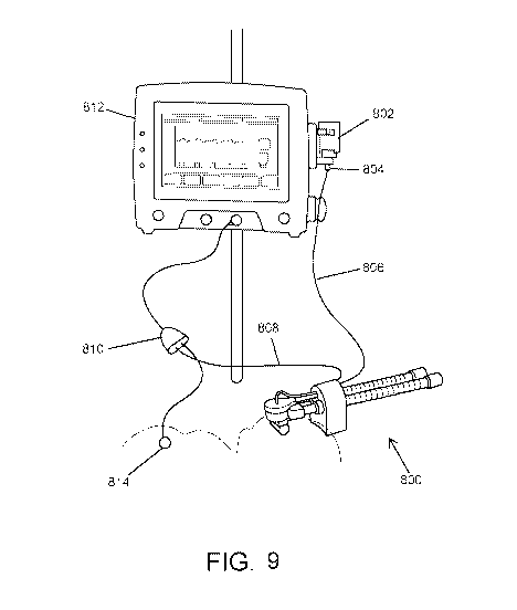
[0080] FIG. 9 illustrates the aerosolization device 800 connected to
medication source
802 and a controller 812. The controller may be configured to cause the liquid
medicament to be delivered to the aerosolization device 800 via the fluid
supply line 806
and to actuate the aerosolization device 800. In some embodiments, the
controller 812
may actuate the aerosolization device 800 based on a detected inhalation of a
patient. For
example, the controller 812 may be coupled with a respiration sensor 814,
which may
detect the start, duration, and/or end of an inhalation of the patient. In
some
embodiments, the respiration sensor 814 may be a sensor similar to a Graseby
sensor,
which may be positioned against a torso (abdomen and/or chest) of the patient
to detect a
respiratory cycle of the patient. As such one example, the controller 812 may
receive a
signal from the respiration sensor 814 that indicates that the patient is
starting to inhale.
The controller 812 may then send commands that cause a volume of liquid
medicament
to be supplied to the aerosol generator of the aerosolization device 800 and
that cause the
aerosol generator to activate to aerosolize the liquid medicament during the
inhalation.
[0081] In some embodiments, the respiration sensor 814 and/or aerosolization
device
800 may be coupled directly to the controller 812. In other embodiments, a pod
810
and/or other adaptor may be used to connect the respiration sensor 814 and/or
aerosolization device 800 with the controller 812. For example, in some
embodiments
connecting the respiration sensor to the pod includes inserting a connection,
such as a slip
Luer, into a port of the pod 810. In the present embodiment, the respiration
sensor 814
may be adhered and/or otherwise affixed to the patient's abdomen to begin
sensing
inspiration cycles
[0082] FIG. 10 illustrates the controller 812. Controller 812 includes a user
interface
818, such as a display screen. In some embodiments, the user interface 818 may
be a
touchscreen. The controller 812 may include one or more input devices, such as
buttons,
dials, keypads, touchscreens, and the like that allow a user to interact with
the controller
812 to adjust settings, such as dose level, etc. The controller 812 may also
include a
number of ports 820 that may be used to connect the controller 812 to
peripheral units,
24
CA 03137299 2021-10-18
WO 2020/243107
PCT/US2020/034576
such as the aerosolization device 800 and/or respiration sensor 814. In some
embodiments, the controller 812 may include one or more indicators 824, such
as LEDs,
that are configured to alert users of the status of various features. For
example, the
indicators 824 may inform users about whether the aerosolization device 800
and/or
respiration sensor 814 are properly connected, whether a power source 832 of
the
controller 812 is active (i.e. plugged in and/or whether a battery (if
present) is charging or
charged), whether any faults in the system have been detected, etc. In some
embodiments, the indicators 824 may be integrated into the user interface 818.
A
housing 822 of the controller 812 may include a holder 826 that is configured
to securely
receive the medication source 802, as best illustrated in FIG. 11. In this
embodiment, the
medication source 802 is a vial that is secured in an upside down orientation
within the
holder 826, allowing the entire contents of the medication source 802 to be
drained,
pumped, and/or otherwise delivered from the medication source 802 to the
aerosolization
device 802.
[0083] FIG. 12 illustrates medication source 802. Here, medication source 802
is in the
form of a vial that is affixed with a vented vial access device (VVAD) 828.
The VVAD
828 may include a removable cap 830 that seals an opening of the VVAD 828 when
affixed to the VVAD 828. The VVAD 828 may also include a filter 832 that helps
minimize aerosols within the vial and fluid supply line 806, minimize surface
contamination, and neutralize vial pressure. In use, the cap 830 may be
removed and a
port (not shown) may be affixed to a Luer connector to couple the medication
source 802
to the fluid supply line 806.
[0084] In some embodiments, the aerosolization devices described herein
include an
aerosol generator capable of coupling to a variety of artificial respiration
systems. The
aerosol generator may receive liquid medicament from a fluid source through a
fluid
delivery conduit. In operation, fluid from the fluid source is pumped with a
pump through
the fluid delivery conduit to the aerosol generator where the fluid is
aerosolized before
and/or while the patient inhales. In some embodiments, the fluid delivery
conduit may be
primed with fluid before treatment to ensure rapid delivery (e.g., preloading
fluid in
aerosol generator). The pump may controlled with a controller, which times
delivery and
dosage of the fluid.
CA 03137299 2021-10-18
WO 2020/243107
PCT/US2020/034576
[0085] The controller includes one or more processors that execute
instructions stored
on one or more memory to drive operation of the pump and the aerosol
generator. For
example, the memory may include instructions that indicate the amount of fluid
to be
pumped to the aerosol generator in each dose for each actuation of the aerosol
generator,
how much fluid is to be pumped over a specific period of time or times, etc.
The stored
instructions may be based on a size of the patient, age of the patient, sex of
the patient,
type of medicament, fluid additives, desired amount of aerosol, etc. The
memory also
includes instructions for activating the aerosol generator. As illustrated,
the controller
connects to the aerosol generator with a cable (i.e., electric cable),
although in some
embodiments the controller may be wirelessly connected to the aerosol
generator. The
cable carries a signal that activates a piezoelectric (or other) actuator
inside the aerosol
generator. As the piezoelectric actuator operates, it vibrates a vibratable
member that
then aerosolizes the fluid for delivery to the patient (i.e., through
inhalation). The
memory may therefore include instructions for controlling when the
piezoelectric
actuator starts, stops, vibration frequency or frequencies, etc.
[0086] The aerosolization systems described herein may increase treatment
effectiveness by timing the creation of the aerosol. For example, the aerosol
delivery
system may begin aerosolizing the medicament before the patient inhales. In
this way,
the aerosol delivery system takes advantage of the increased airflow at the
start of
inhalation. This increases the medicament delivery to the patient as the
inhaled air
carries the medicament farther into the patient's lungs. The aerosol delivery
system may
also aerosolize medicament as soon as inhalation is detected (e.g., for
spontaneous
breathing).
[0087] The aerosol delivery system coordinates delivery of the medicament
using one
or more breath sensors to determine when a patient inhales and for how long.
These
breath sensors may communicate with the controller through wired connections
and/or
wireless connections. In some embodiments, the aerosol delivery system may use
a
combination of breath sensors to provide redundancy and/or more accurate
monitoring of
the patient's breathing cycle. As just one example, the aerosol delivery
system may use a
flow sensor in combination with a radar sensor to monitor both airflow and
chest
movement. As another example, the aerosol delivery system may use a flow
sensor, a
26
CA 03137299 2021-10-18
WO 2020/243107
PCT/US2020/034576
radar sensor, and plethysmography sensor to monitor the breathing cycle. It
will be
appreciated that any number and/or any combination of breath sensors may be
utilized in
a given application to monitor the patient's breathing cycle.
[0088] In some embodiments, the flow sensor couples to a gas delivery conduit
to
sense changes in airflow during inhalation (e.g., mandatory, assisted, or
spontaneous
breathing). In some embodiments, the flow sensor may also couple to a gas
return
conduit to detect the start and end of exhalation. And in still other
embodiments, the
aerosol delivery system may include flow sensors that couple to the gas
delivery conduit
and the gas return conduit. As the controller receives data from the flow
sensor(s), the
controller may monitor breathing patterns to predict when the patient is going
to breath.
The ability to predict when inhalation begins enables the aerosol delivery
system to
prepare aerosolized medicament for immediate inhalation. More specifically,
the aerosol
delivery system is able to preload fluid on a vibratable member in the aerosol
generator
so that the fluid can be aerosolized before inhalation. Because flow detection
is not a
lagging indicator, the flow sensor can rapidly detect unusual or spontaneous
inhalation
for aerosol delivery (e.g., less than 10 milliseconds from the start of
inhalation).
[0089] Predicting the patient's inhalation may begin by using one or more
breath
and/or flow sensors to tracking the patient's breathing pattern and/or a
ventilation cycle
(if a patient is mandatorily ventilated). The controller then uses the tracked
data to
predict when subsequent inhalations will begin. This allows the controller to
direct the
pump to deliver fluid from the fluid source to the aerosol generator 16 prior
to an
inhalation. The controller may also signal the aerosol generator to begin
aerosolizing the
fluid at a proper time, such as within a predetermined time period (e.g., +/-
0.5 seconds)
before and/or during the predicted inhalation. In this way, aerosol is ready
for the patient
at the start of inhalation. While the aerosol delivery system is able to
predict the breath
cycle to produce aerosol for the patient, the aerosol delivery system is also
able to
recognize spontaneous/irregular breathing not part of the normal pattern using
the breath
sensors. Once a spontaneous breath is recognized, the aerosol delivery system
may
immediately pump fluid to the aerosol generator for delivery to the patient.
27
CA 03137299 2021-10-18
WO 2020/243107
PCT/US2020/034576
[0090] FIG. 13 illustrates one example of the functionality of the controller
812. As
shown in plot A, the controller 812 receives a signal from the respiration
sensor 814 that
indicates that the patient has begun an inhalation. The controller 812 then
sends
commands that initiate the delivery of a volume of medicament to the aerosol
generator,
which activates to aerosolize the liquid medicament as illustrated in plots B-
D. In some
embodiments, the controller 812 may be programmed to cause the aerosolization
of
medicament only for a first portion of an inhalation, allowing for a final
portion of the
inhalation to drawn in chase air to help deliver the aerosolized medicament
into the deep
lungs. For example, as shown in the various plots, the controller 812 causes
the
aerosolization of medicament only within the first 80% of each inhalation,
allowing the
final 20% of each inhalation to draw chase air into the patient's airways. It
will be
appreciated that other aerosolization patterns may be used. For example, the
aerosolization of medicament may be done within the first 50%-90% (more
commonly
between 60%-80% and even more commonly between 70% and 80%) of each
inhalation.
Times greater than 80% are associated with more aerosol in the upper airway
that is
exhaled prior to reaching the lower airways. This allows the final 10%-50%
(more
commonly between about 20%-40% and even more commonly between 20% and 30%)
of the inhalation to be used to draw chase air into the patient's airways.
[0091] A set up process for using the aerosolization system of FIGs. 8-13 is
illustrated
in FIGs. 14A-14K. To start, the controller 812 may be powered on (such as by
turning on
a switch), allowing the controller 812 to begin a start-up sequence. In some
embodiments, the start-up sequence may include a power-on self-test of the
range of any
audible alarms and/or the alarm display at the top of the controller cycling
through the
range of visual alarms. A backup alarm for the system may also be sounded as a
test. As
shown in FIG. 14A, a user (such as medical personnel) may need to log into the
controller 812 using user interface 818. For example, the user may need to
enter
credentials, such as a user name, password, possession-based credential (such
as a
magnetic stripe card and/or a digital key or credential provided using a radio
frequency
communications protocol), biometric credential (fingerprint scan, facial scan,
retinal
scan, voice scan, and the like), etc. to begin using the aerosolization
system. Once logged
in, the user may need to provide patient information, which may be pertinent
to the
28
CA 03137299 2021-10-18
WO 2020/243107
PCT/US2020/034576
timing, volume, and/or other factors associated with treatment of the patient.
For
example, as illustrated in FIG. 14B, a user must enter a patient identifier
(such as a name,
identification number, etc.), a weight of the patient, a dosage type
(high/low, etc.) and/or
amount, and/or other details associated with the patient. After entering all
necessary
patient information, the user may be presented with a confirmation screen that
allows the
user to review and confirm the accuracy of the patient and dosing information
prior to
proceeding. If the patient and dosing information are correct, the user may
confirm and
continue with the set up process. If any of the patient or dosing information
is incorrect,
the user may re-input the incorrect information prior to proceeding.
[0092] The user may then be presented with instructions on using the
aerosolization
system as shown in FIG. 14C. Here, the user interface 818 instructs the user
to connect
pod 810 to the controller 812 of the aerosolization system. For example, the
user may
insert a connector of the pod 810 into one of the ports 820 of the controller
812. In some
embodiments, the user interface 818 may display a notification when the pod
810 is
properly connected to the controller 812. In some embodiments, the controller
812
and/or a stand (not shown) on which the controller 812 may be affixed and/or
otherwise
supported may include a basket and/or other support structure that may be used
to hold
any excess cable from the pod 810. Other instructions may be presented that
help a user
set up the aerosolization system for use. As another example, in FIG. 14D the
user
interface 818 may instruct the user to connect respiration sensor 814 (such as
a
respiration sensor capsule) to both the pod 810 and to the patient and then
confirm an
inhalation of the patient. As illustrated, in some embodiments connecting the
breath
sensor to the pod includes inserting a connection, such as a slip luer, into a
port of the pod
810. In the present embodiment, the respiration sensor 814 may be adhered
and/or
otherwise affixed to the patient's abdomen to begin sensing inspiration
cycles. For
example, the skin of the patient may be prepared using an adhesive barrier
wipe and
allowed to dry. The respiration sensor 814 may then be placed on the lateral
and/or lower
abdomen and taped in place, with tubing of the respiration sensor 814 being
free of tape.
The user interface 818 may prompt the user to confirm that a breath signal was
received
by the controller 812 and properly displayed on the user interface 818.
29
CA 03137299 2021-10-18
WO 2020/243107
PCT/US2020/034576
[0093] As shown in FIG. 14E, the user may be presented with instructions on
how to
set up the aerosolization system's drug feed line 806 and nebulizer cable 808.
For
example, the user may attach VVAD 828 to a vial of medicament (medication
source
802), with filter 832 aligned with a viewing window on a label of the vial.
This may be
done by holding the vial upright and placing a piercer (not shown) of the VVAD
828
through a septum (not shown) of the vial until the VVAD 828 clicks and locks
into place.
A feed mechanism (such as a pump, not shown) may be opened, such as on a side
of the
housing of the controller 812, and fluid supply line 806 is inserted into the
feed
mechanism, which is then closed. The vial may be placed into a horizontal
orientation
and coupled with the fluid supply line 806. A luer end of the VVAD 828 may be
placed
into a luer holder portion of the holder 826 and pivoted up into a metal clip
with a
viewing window facing outwards. Nebulizer cable 808 may then be coupled with
pod
810. The aerosolization device 800 may also be coupled with a respiration
system, such
as a ventilator. Once the various components are connected, the aerosolization
device
800 may be primed.
[0094] FIG. 14F demonstrates priming the pump. This may be done by selecting a
prime function using the user interface 818 of the controller 812. Once
primed, an
aerosol check may be performed, as shown in FIG. 14G. The user may then
interact with
the user interface 818 to start the aerosol generation. The user may then
observe for
aerosol being produced and emitted from the patient interface (if affixed) or
from an
opening in the aerosolization device 800 to ensure that the aerosolization
system is
functioning properly. If aerosol is observed, the user may proceed with the
set up. If
aerosol is not observed, the user may repeat the priming and aerosol check
steps. Before
or after the aerosol check is completed, the user interface 818 may prompt the
user to
couple a patient interface (such as nasal prongs) with the aerosolization
device 800. The
user may select the proper size of patient interface and press the patient
interface onto the
aerosolization device 800. In some embodiments, the connection between the
patient
interface and the aerosolization device 800 may be trapezoidal. This shape may
help the
user properly align the patient interface in a correct orientation, although
other shapes
may be used. As shown in FIG. 14H, the aerosolization device 800 may be
connected to
an infant. For example, the nasal prongs (or other patient interface) may be
interfaced
CA 03137299 2021-10-18
WO 2020/243107
PCT/US2020/034576
with the infant's airways. In some embodiments, one or more straps and/or
other
restraints may be used to secure the aerosolization device 800 to the infant's
airways and
head to ensure that the aerosolization device stays in place if the infant
moves. In some
embodiments, the aerosolization device 800 may be secured to the infant's head
using
one or more straps that may be secured to a bonnet worn by the infant.
Additionally, a
foam pad may be affixed to the aerosolization device 800 that may extend
between the
aerosolization device 800 (spaced laterally apart from a portion of the
aerosolization
device 800 having the aerosol generator) and the infant's head. The foam pad
may
include multiple layers of peel able foam, allowing the layers to be peeled
off and/or
otherwise removed to adjust a distance between the aerosolization device 800
and the
infant's head. Oftentimes, the foam pad may include a curved surface that is
designed to
match or substantially match a contour of the infant's head. Once in position,
the foam
pad (along with any straps) helps maintain the aerosolization device 800 at a
proper
position and orientation with the infant, regardless of the movement or
orientation (back,
side, stomach) of the infant. Once the aerosolization system is connected to
the infant,
the user may interact with the user interface 818 to begin dosing of the
infant as shown in
FIG. 141. For example, the user may confirm the patient data and total dose,
as well as
verify that a number of vials of medication matches a Pharmacy Calculation and
Dispensing Form from a pharmacist. Once the data is confirmed, the user may
interact
with the controller 812 to begin a dosing procedure. Once the dosing procedure
is
initiated, data such as breath cycles, dose indications, nebulization rate,
remaining
medication volume in the medication source 802, etc. The user interface 818
may also
prompt the user to confirm that the aerosol is in sync with the infant's
breathing pattern.
[0095] In some embodiments, when the vial is empty, the controller 812 halts
the
dosing. Oftentimes, when a threshold volume of medicament (such as less than
5%,
10%, 15%, 20%, etc.) remains in the vial, a low priority alarm may activate.
After a set
period of time, if the low priority alarm is not acknowledged by the user, a
medium
priority alarm will activate and "Vial Alert" may be displayed on user
interface 818
and/or produced at one of the indicators 820. In some embodiments, when the
vial is
empty, the controller 812 auto pauses, and a medium alarm is activated. If
after a
predetermined time, the user has not acknowledged the alarm, a high priority
alarm is
31
CA 03137299 2021-10-18
WO 2020/243107
PCT/US2020/034576
activated. The user may be prompted to "Replace vial, restart dose from drug
delivery
screen". A new vial of medicament may be swapped in for the empty vial and
dosing
may continue. Once the dosing is complete, the user may confirm the end of
dosing and
interact with the controller 812 to return to a normal CPAP or other
respiration circuit.
[0096] In some embodiments, low priority alarms are visual only and annunciate
only
with text on user interface 818. In some embodiments, medium priority alarms
have
visual and audio components, incorporating an associated colored alarm display
(such as
yellow) with associated audio and text. In some embodiments, high priority
alarms have
visual and audio components, incorporating an associated colored display box
(such as
red) on the user interface 818 with text on the user interface 818. In some
embodiments,
alarms may be provided for one or more of the following non-limiting events:
if
respiration is not detected, if a valid breath sequence has not been detected
(which may
occur if a valid breath sequence has not been detected where a valid breath
sequence
consists of three consecutive valid breaths in which a valid breath is
determined as an
Inhalation period >100mSec duration, an invalid breath sequence consists of at
least one
invalid breath, and an invalid breath is determined as an Inhalation period
<100mSec
duration), if the nebulizer cable is disconnected from the Pod during dosing,
if no wet/dry
events are detected (such as due to a kink in tubing that prevents the drug
from getting to
the aerosol generator, not nebulizing and all of the drug is coming out a vent
hole,
nebulizing with no drug coming out of the vent hole, nebulizing and also drug
coming out
of the vent hole), if a remaining volume in the vial is at or less than a
threshold amount
(including empty), if the pod cable is disconnected from the Pod during
dosing, if the pod
cable is disconnected from the pod when not dosing, if communication failure
is detected
with the pod, if a pod internal failure is detected, if a system error is
detected, if the drug
feed mechanism fails, if the mains is disconnected and is being operated in
battery mode,
if a battery is at or below a threshold level of charge (including empty),
and/or if the
power on a self-test fails.
[0097] FIG. 15 illustrates an aerosolization device 1500 interfaced with an
infant.
Here, the aerosolization device 1500 may be similar to those described herein
and places
an aerosol generator proximal to the infant's airway and includes baffling
that minimizes
flow through the immediate patient aerosol generator/interface area during
periods of
32
CA 03137299 2021-10-18
WO 2020/243107
PCT/US2020/034576
aerosol generation. The aerosolization device 1500 may also include a PDAP
mesh or
similar mesh that enables aerosolization of particles having an IVINIAD of
less than about
3 p.m (more preferably less than about 2 p.m) to be generated at high flow
rates (between
about 0.1 ml/min and 1.5 ml/min). The aerosolization device 1500 may also
include a
power/control port that allows one or more controllers (similar to controller
812) to be
connected to supply power and/or operational commands to the aerosol
generator.
[0098] The aerosolization device 1500 may also include one or more straps or
other
restraints 1502 that enable the aerosolization device 1500 to be secured with
the infant's
head and airways. Additionally, the aerosolization device 1500 may include a
foam pad
1504 that is designed to help maintain the aerosolization device 1500 at a
proper position
and orientation with the infant, regardless of the movement or orientation
(back, side,
stomach) of the infant The foam pad 1504 may include multiple layers of peel
able foam,
allowing the layers to be peeled off and/or otherwise removed to adjust a
distance
between the aerosolization device 1500 and the infant's head. Oftentimes, the
foam pad
1504 may include a curved surface that is designed to match or substantially
match a
contour of the infant's head. The aerosolization device 1500 may be
constructed of
sufficiently light materials (such as medical-grade plastic foam) that allow
the infant to
move around without causing the aerosolization device 1500 to shift out of
proper
position.
[0099] FIG. 16 illustrates a respiration sensor capsule 1600 (similar to
respiration
sensor 814) interfaced with an infant's abdomen. As shown, the respiration
sensor
capsule 1600 is taped and/or otherwise adhered to the infant's abdomen and is
then used
to detect the beginning and/or end of the infant's inspiration cycles. This is
done using
changes in the volume of the sensor capsule 1600 in response to movement of
the
abdomen that is associated with breathing. Using data from one or more
inspiration
cycles, a controller (not shown) may monitor flows entering and leaving the
capsule
associated with volume changes in the abdominal sensor and synchronize
delivery of
aerosolized surfactant with the infant's inhalation to help maximize delivery
efficiency of
the surfactant.
33
CA 03137299 2021-10-18
WO 2020/243107
PCT/US2020/034576
[0100] FIG. 17 illustrates another embodiment of an aerosolization system 1700
for
delivering surfactants to an infant in an effective and efficient manner. As
illustrated, a
controller 1702 (which may be similar to controller 812) is used to provide
power and
control to an aerosolization device 1704. The controller 1702 may also be
configured to
control a delivery mode of the aerosolization device 1704. For example, the
controller
1702 may be configured to alternate between a timed mode in which a treatment
is given
over a set period of time, or a continuous mode in mode the delivery of
aerosolized
surfactant is done indefinitely based on the infant's inhalation patterns.
System 1700
may also include an additional controller 1706 that allows medical personal to
set aerosol
delivery criteria. For example, the additional controller 1706 may enable a
flow rate that
triggers delivery of aerosol, an inspiratory time for delivery of aerosol,
and/or other
criteria that control the timing, dosage, and/or duration of the aerosolized
dosage. While
described with controller 1702 and additional controller 1206 being different
components, it will be appreciated that in some embodiments a single
controller (or more
controllers) may be used to control the operation of system 1700.
[0101] System 1700 may also include one or more flow sensors and/or other
breath
sensors 1708. As illustrated, flow sensor 1708 may be coupled with an
inspiratory limb
1710 of a respiration system 1712, such as before and/or after an optional
humidifier
1714. The breath sensor 1708 may be sued to detect an inhalation of the
infant. In other
embodiments, the breath sensor 1708 may be a respiration sensor capsule that
is
interfaced with the infant's abdomen. The breath sensor 1708 may be
electronically
coupled with one or both of the controllers 1702 or 1706 such that the
inhalation data
may be used to trigger activation of the aerosolization device 1704 (which may
be similar
to any of the aerosolization devices described herein). The controllers 1702
and 1706
may be electronically coupled with the aerosolization device 1704 to provide
both power
and operating commands to the aerosolization device 1704. In some embodiments,
the
aerosolization device 1704 may include a PDAP mesh 1716 that produces
aerosolized
surfactant having a IVINIAD of less than about 3 p.m (preferably less than
about 2 p.m) at a
rate of at least 0.1 ml/min. Such aerosolization devices 1704, when used in
conjunction
with controllers 1702, 1706 and breath sensors 1708, allow for 1) the
generation and
delivery sufficiently small aerosol particles, 2) breath synchronized aerosol
delivery, and
34
CA 03137299 2021-10-18
WO 2020/243107
PCT/US2020/034576
3) placement of the aerosol generator proximal to the infant's airway with
baffling of
continuous gas flow to minimize flow through the immediate patient aerosol
generator/interface area during periods of aerosol generation (as best
illustrated in FIGs.
6-6D), thereby enabling vastly improved delivery efficiency rates to the lungs
of between
about 25%-60%, and more commonly between about 40%-60%.
[0102] FIG. 18 is a flowchart of a process 1800 for delivering aerosolized
surfactant to
an infant. Process 1800 may be performed using any of the aerosolization
devices,
processors, and/or respiration sensors described herein. Process 1800 may
begin at block
1802 by detecting an inhalation of an infant using one or more breath sensors.
For
example, a breath sensor may be affixed to the abdomen of the infant. The
breath sensor
may detect the expansion of the infant's abdomen that is associated with an
inhalation.
Based on this detected inhalation, a controller may cause an aerosolization
device to
aerosolize a volume of surfactant into particles having a mass mean
aerodynamic
diameter (MMAD) of less than about 3 um at a rate of at least 0.1 ml/min at
block 1804.
The surfactant may be aerosolized within about 1 to 8 cm from a patient
interface. In
some embodiments, aerosolizing the volume of the surfactant may include
delivering the
volume of the surfactant from a reservoir to a mesh of the aerosol device and
vibrating
the mesh to aerosolize the volume of the surfactant. In some embodiments, the
volume
of the surfactant is delivered from the reservoir to the mesh via a conduit
having a
distalmost tip with a diameter. The distalmost tip of the conduit may be
positioned at a
distance from a mesh of the aerosol generator that is less than or equal to
the diameter.
This ensures that any medicament ejected from the tip contacts and wicks along
a surface
of the mesh, enabling the aerosolization device to effectively operate at any
orientation.
In some embodiments, aerosolizing the volume of the surfactant involves
aerosolizing a
portion of the volume of surfactant within at least a portion of a first 80%
of each of a
successive number of inhalations such that chase air is provided within at
least a portion
of a final 20% of each of the successive number of inhalations. At block 1806,
the
aerosolized surfactant may be delivered to the infant's airway via a patient
interface, such
as nasal prongs.
[0103] In some embodiments, the process 1800 may also include coupling the
aerosolization device with a respiration system and diverting a portion of
airflow from
CA 03137299 2021-10-18
WO 2020/243107
PCT/US2020/034576
the respiration system into a chamber of the aerosolization device via at
least one airway.
The chamber is configured to mix the portion of the airflow with aerosolized
surfactant.
In some embodiments, the portion of airflow is respiratory flow and is less
than an
amount of air that continues to an expiratory limb of the respiration system.
In some
embodiments, the portion of airflow is diverted using at least one baffle that
defines the at
least one airway. The at least one baffle may be configured to divert the
portion of
airflow into the aerosol chamber via the at least one airway and to divert an
additional
portion of airflow from the inspiratory limb to the expiratory limb. In some
embodiments, two baffles are used. A first baffle may define a first airway
and a second
baffle may defines a second airway. The first airway is provided at a lateral
end of the
first baffle and the second airway is provided beyond a distal edge of the
second baffle,
with the lateral end and the distal edge extending in different directions
such that the
respiratory flow moves in multiple directions to pass the first baffle and the
second
baffle.
[0104] FIG. 19 is a flowchart of a process 1900 for initializing an
aerosolization
system. Process 1900 may be performed using any of the aerosolization devices,
processors, and/or respiration sensors described herein. Process 1900 may
begin at block
1902 by connecting an aerosolization device with a controller, a respiration
sensor, a
medication source, and a respiration system. This may involve coupling a
nebulizer
cable between the aerosolization device and the controller (possibly via a pod
or other
adaptor), coupling an inspiratory limb of the respiration system with an inlet
of the
aerosolization device, coupling an expiratory limb of the respiration system
with an outlet
of the aerosolization device, coupling a cable of the respiration sensor with
the controller
(possibly via a pod or other adaptor), and/or coupling the aerosolization
device with the
medication source. In some embodiments, coupling the aerosolization device
with the
medication source may include coupling a fluid supply line between the
medication
source and the aerosolization device. In some embodiments, the medication
source is a
vented vial access device (VVAD) that is coupled with the fluid supply line.
[0105] At block 1904, a user's access credentials are input into the
controller, ensuring
that only authorized users have access to the aerosolization system and the
ability to
administer medicament. The access credential may include one or more of a user
36
CA 03137299 2021-10-18
WO 2020/243107
PCT/US2020/034576
identifier, a password, a possession-based credential, and a biometric
credential.
Information associated with a patient and dose information may be input into
the
controller at block 1906. This may include information such as a patient
identifier, a
weight of the patient, a dosage level, and the like. At block 1908, the
respiration sensor
may be coupled with a patient. This may involve adhering the sensor to the
patient's
abdomen. In some embodiments, a detection of breath may be configured after
coupling
the respiration sensor with the patient. At block 1910, the aerosolization
device may be
primed. This may include aerosolizing a portion of medicament prior to
interfacing the
patient interface with the patient's airways to ensure the device is
functioning properly.
At block 1912, the aerosolization device may be interfaced with the patient's
airways.
For example, nasal prongs may be inserted into the nostrils of the infant. In
some
embodiments, the patient interface may need to be secured to the
aerosolization device
prior to interfacing the device with the patient. In some embodiments, one or
more straps
and/or foam pads may be positioned and/or secured about the infant to secure
the
aerosolization device in place. Once secured in place, a user may initiate
delivery of a
dosage to the infant and/or may review a user interface of the controller to
confirm that
delivery of aerosolized doses are in sync with the infant's inhalations.
[0106] In some embodiments, the process 1900 may also include performing a
start-up
sequence upon powering on the controller. The start-up sequence may cycle
through a
number of audio alarms, visual alarms, or both audio and video alarms to
ensure the
controller is functioning properly prior to use.
[0107] EXAMPLES
[0108] In vitro experiments were conducted to determine the effective emitted
dose of
medicament using an aerosolization device in accordance with the present
invention.
Simulated infant inhalations were performed using a modified Harvard Apparatus
sinusoidal small animal ventilator and an Ingmar Lung Simulator interfaced
with a
patient adaptor (here in the form of nasal prongs) of an aerosolization device
similar to
that described in FIGs. 6-6D. Simulations were performed using two different
sizes of
nasal prongs, with a larger nasal prong (5560) and a smaller nasal prong
(4030). As seen
in the bar graph illustrated in FIG. 20, the larger the prong size, the higher
the emitted
37
CA 03137299 2021-10-18
WO 2020/243107
PCT/US2020/034576
dose. Notably, the larger nasal prong (5560) resulted in emitted doses of
between 68%
and 72% emitted dose while the smaller nasal prong (4030) resulted in emitted
doses of
between about 35% and 37%.
[0109] The air flow was then set to 6 liters per minute (LPM), 8 LPM, and 10
LPM and
with breathing rates of 60 breaths per minute (BPM), 80 BPM, 100 BPM, and 120
BPM.
Emitted dose rates were then measured at each combination of air flow rate and
breathing
rate. As illustrated in FIG. 21, gas flow has an effect on delivery
efficiency, with greater
flow rates leading to slightly lower delivery efficiencies. For example, at
lower flow
rates (6 LPM), the larger nasal prongs (5560) resulted in approximately 50% to
about
60% emitted dose at the extreme ends of the tested breathing rates, while at
higher flow
rates (10 LPM) the emitted dose ranged from about 42% to about 47%. It is
noted that as
the breathing rates increased, the difference in efficiency associated with
greater flow
rates becomes less pronounced. For example, the range of emitted dose rates at
60 BPM
was about 44% to about 60%, while at 120 BPM the emitted dose rates ranged
from
about 42% to about 51%. Based on these results, it was determined that the
aerosol
generators described herein enables consistent inhaled dose of medicament
across a
clinically relevant range of respiratory rates (60-120 BPM) and CPAP flows (6-
10 LPM)
commonly used with bubble and vent CPAP systems.
[0110] Embodiments of the present invention also provide systems and methods
for
delivering surfactants (or other medicaments) to infants, particularly preterm
infants, in a
non-invasive manner. In order to achieve effective and efficient
administration of
medical aerosols to preterm infants, a combination of attributes is required:
1) sufficiently
small aerosol particles, 2) breath synchronized aerosol delivery, and 3)
placement of the
aerosol generator proximal to the infant's airway (within about 1-8 cm) with
baffling of
continuous gas flow to minimize flow through the immediate patient aerosol
generator/interface area during periods of aerosol generation. By satisfying
these
conditions, surfactant delivery rates exceeding 40% and up to about 60% are
achievable,
which provide significant improvements over conventional efficiency rates of
less than
10%.
38
CA 03137299 2021-10-18
WO 2020/243107
PCT/US2020/034576
[0111] Due to the breathing physiology of preterm infants, in order to
properly delivery
aerosolized surfactant to an infant in a non-invasive it is necessary to
utilize nasal
delivery techniques, such as nasal prongs that are insertable within the nasal
passages of
the infant. Using such delivery techniques, it is desirable to deliver aerosol
particles that
are less than about 2 p.m, as particles larger than this are typically
impacted out in the
interface of the aerosolization device and/or in the airways prior to being
dispersed in the
infant's lungs. This is shown in FIGs. 22 and 23, which demonstrate particle
deposition
rates for various particle sizes (using MMAD and a GSD of 2.2) for neonates,
with
neonate 1 being 4 months old and neonate 2 being preterm 28 weeks. FIG. 22
illustrates
that as particle size decreases the lung deposition increased (FIG. 22 only
shows results
for neonate 1), with lung deposition surpassing 40% as particle sizes fall
below 2 p.m.
Notably, for particles larger than 2 p.m the nasal deposition is typically
between about
50%-70%, which represents particles that are not delivered to the infant's
lungs. FIG. 23
illustrates lung vs. nasal deposition rates for both neonates using a 3 p.m
MMAD and a 2
tm MMAD aerosol. Here, for both neonates improved lung deposition is observed
for
the aerosol of 2 p.m MMAD, with deposition rates being just under 40% for
neonate 1
and just under 60% for neonate 2. These results demonstrate the need for
smaller aerosol
particles in order to maximize delivery efficiency.
[0112] Conventional nasal delivery techniques typically utilize particles
having a 4-7
tm MMAD, with a geometric standard deviation of approximately 2.0 or higher.
This is
due to the viscous nature of most surfactants, which makes it very difficult
to aerosolize
undiluted surfactant into particles of sufficiently small sizes at
sufficiently high
aerosolization rates to be effective using conventional jet nebulizers,
specialty jet
nebulizers, mesh nebulizers, heated capillary generators, and the like. As
such
conventional delivery techniques see impaction rates that reduce the available
mass of
aerosol in a given dose by up to 80%. Only 40-60% of the remaining aerosol
(that
portion made up of particles having less than about 2 p.m) would then reach
the lower
airways of the lungs, resulting in a total efficiency rate of approximately
10% of the
initial emitted dose from the aerosol generator.
[0113] Embodiments of the present invention provide systems and methods that
generate sufficiently small aerosol particles using aerosolization devices
such as those
39
CA 03137299 2021-10-18
WO 2020/243107
PCT/US2020/034576
described in relation to Figures 1-8 above. In particular, embodiments utilize
aerosolization devices that include aerosol generators that leverage the
capabilities of a
PDAP mesh (such as disclosed in U.S. Patent Publication No. 2016/0130715,
previously
incorporated by reference) to consistently generate aerosolized surfactant
having less than
about 3 [tm (and more preferably, a range of about 1.5 [tm to about 2.5 [tm)
at output
rates of between about 0.1 ml/min and 0.6 ml/min. By leveraging the
capabilities of such
aerosol generators, embodiment of the present invention are able to provide
sufficiently
small particle sizes for effective and efficient delivery of surfactant to the
lungs. For
example, even with an aerosol having an MMAD of less than 3 [tm achieves a
trans-nasal
pulmonary efficiency of about 40-60% of the nominal dose of surfactant.
[0114] As noted above, to fully maximize delivery efficiency, it is also
useful to
synchronize the aerosol delivery with the infant's inhalations. This helps
ensure that
surfactant is not wasted when aerosolized during exhalation and/or periods
between
breaths. For example, infants typically have inspiratory:expiratory ratios
ranging from
about 1:1 to about 1:3. Accordingly, aerosolized surfactant is typically only
inhaled for
about 25-50% of the time. In conventional systems, this aerosol is typically
carried by a
gas flow of between about 6-10 LPM with a bubble CPAP, which exceeds the
infant's
peak inspiratory flows and results in wasting up to half the aerosolized
medicament.
[0115] Embodiments of the invention may tie the activation of the aerosol
generator to
the infant's breath. As described above, this may be done using one or more
breath
and/or flow sensors to tracking the patient's breathing pattern and/or a
ventilation cycle.
A controller then uses this information to predict when subsequent inhalations
will begin
and times delivery of fluid from the fluid source to the aerosol generator
and/or activation
of the aerosol generator to be approximately synchronized with the infant's
inhalation. In
some embodiments, the detection of inhalations may be done using a respiration
sensor
capsule attached to the infant's abdomen. The respiration sensor capsule may
detect
movement of the abdomen associated with inhalations, which typically occurs
just before
the inhalation itself occurs, making the respiration sensor capsule
particularly useful in
determining inhalation timing for synchronization of aerosol generation.
CA 03137299 2021-10-18
WO 2020/243107
PCT/US2020/034576
[0116] The effectiveness of the respiration sensor capsule in detecting
inhalations is
demonstrated in FIG. 24. Here, separate flow sensors were interfaced with an
infant's
airway and a respiration sensor capsule secured to the infant's abdomen. The
infant
weighed 1,500 g and had a respiratory rate of 70 BPM. The plot in FIG. 24
shows that
the sensor signal from the respiration sensor capsule detected each inhalation
and
exhalation that was detected by the flow sensor, with the respiration sensor
capsule
detecting the beginning of the inhalation slightly before the flow sensor,
which enables
time for the controller to activate the aerosol generator. These results
confirm that the
use of a respiration sensor capsule may be particularly useful for
synchronizing breaths
and aerosol generation. FIG. 24 also demonstrates that this particular set of
inhalations
was over a period of 5 seconds, with inhalations only taking up approximately
1/3 of the
time period. Thus, without synchronizing breath and aerosol delivery, over 2/3
of the
dose of aerosolized surface would be wasted.
[0117] In some embodiments, the aerosolization devices described herein
include an
aerosol generator capable of coupling to a variety of artificial respiration
systems. The
aerosol generator may receive liquid medicament from a fluid source through a
fluid
delivery conduit. In operation, fluid from the fluid source is advanced with a
pump
through the fluid delivery conduit to the aerosol generator where the fluid is
aerosolized
before and/or while the patient inhales. In some embodiments, the fluid
delivery conduit
may be primed with fluid before treatment to ensure rapid delivery (e.g.,
preloading fluid
in aerosol generator). The pump may controlled with a controller, which times
delivery
and dosage of the fluid.
[0118] The controller includes one or more processors that execute
instructions stored
on one or more memory to drive operation of the pump and the aerosol
generator. For
example, the memory may include instructions that indicate the amount of fluid
to be
pumped to the aerosol generator in each dose for each actuation of the aerosol
generator,
how much fluid is to be pumped over a specific period of time or times, etc.
The stored
instructions may be based on a size of the patient, age of the patient, sex of
the patient,
type of medicament, fluid additives, desired amount of aerosol, etc. The
memory also
includes instructions for activating the aerosol generator. As illustrated,
the controller
connects to the aerosol generator with a cable (i.e., electric cable),
although in some
41
CA 03137299 2021-10-18
WO 2020/243107
PCT/US2020/034576
embodiments the controller may be wirelessly connected to the aerosol
generator. The
cable carries a signal that activates a piezoelectric (or other) actuator
inside the aerosol
generator. As the piezoelectric actuator operates, it vibrates a vibratable
member that
then aerosolizes the fluid for delivery to the patient (i.e., through
inhalation). The
memory may therefore include instructions for controlling when the
piezoelectric
actuator starts, stops, vibration frequency or frequencies, etc.
[0119] The aerosolization systems described herein may increase treatment
effectiveness by timing the creation of the aerosol. For example, the aerosol
delivery
system may begin aerosolizing the medicament before the patient inhales. In
this way,
the aerosol delivery system takes advantage of the increased airflow at the
start of
inhalation. This increases the medicament delivery to the patient as the
inhaled air
carries the medicament farther into the patient's lungs. The aerosol delivery
system may
also aerosolize medicament as soon as inhalation is detected (e.g., for
spontaneous
breathing).
[0120] The aerosol delivery system coordinates delivery of the medicament
using one
or more breath sensors to determine when a patient inhales and for how long.
These
breath sensors may communicate with the controller through wired connections
and/or
wireless connections. In some embodiments, the aerosol delivery system may use
a
combination of breath sensors to provide redundancy and/or more accurate
monitoring of
the patient's breathing cycle. As just one example, the aerosol delivery
system may use a
flow sensor in combination with a radar sensor to monitor both airflow and
chest
movement. As another example, the aerosol delivery system may use a flow
sensor, a
radar sensor, and plethysmography sensor to monitor the breathing cycle. It
will be
appreciated that any number and/or any combination of breath sensors may be
utilized in
a given application to monitor the patient's breathing cycle.
[0121] In some embodiments, the flow sensor couples to a gas delivery conduit
to
sense changes in airflow during inhalation (e.g., mandatory, assisted, or
spontaneous
breathing). In some embodiments, the flow sensor may also couple to a gas
return
conduit to detect the start and end of exhalation. And in still other
embodiments, the
aerosol delivery system may include flow sensors that couple to the gas
delivery conduit
42
CA 03137299 2021-10-18
WO 2020/243107
PCT/US2020/034576
and the gas return conduit. As the controller receives data from the flow
sensor(s), the
controller may monitor breathing patterns to predict when the patient is going
to breath.
The ability to predict when inhalation begins enables the aerosol delivery
system to
prepare aerosolized medicament for immediate inhalation. More specifically,
the aerosol
delivery system is able to preload fluid on a vibratable member in the aerosol
generator
so that the fluid can be aerosolized before inhalation. Because flow detection
is not a
lagging indicator, the flow sensor can rapidly detect unusual or spontaneous
inhalation
for aerosol delivery (e.g., less than 10 milliseconds from the start of
inhalation).
[0122] Predicting the patient's inhalation may begin by using one or more
breath
and/or flow sensors to tracking the patient's breathing pattern and/or a
ventilation cycle
(if a patient is mandatorily ventilated). The controller then uses the tracked
data to
predict when subsequent inhalations will begin. This allows the controller to
direct the
pump to deliver fluid from the fluid source to the aerosol generator prior to
an inhalation.
The controller may also signal the aerosol generator to begin aerosolizing the
fluid at a
proper time, such as within a predetermined time period (e.g., +/- 0.5
seconds) before
and/or during the predicted inhalation. In this way, aerosol is ready for the
patient at the
start of inhalation. While the aerosol delivery system is able to predict the
breath cycle to
produce aerosol for the patient, the aerosol delivery system is also able to
recognize
spontaneous/irregular breathing not part of the normal pattern using the
breath sensors.
Once a spontaneous breath is recognized, the aerosol delivery system may
immediately
pump fluid to the aerosol generator for delivery to the patient.
[0123] EXAMPLE 1
[0124] A two part trial was conducted to determine safety and tolerability of
dose of
inhaled surfactant in preterm infants at risk for worsening RDS, while
receiving nCPAP..
Part 1(10 infants) involved treating patients with a single dose and Part II
involved
multiple doses. 31 preterm infants in total who required nCPAP (machine CPAP)
were
enrolled into the study. Infants were initially stabilized on nCPAP/nIMV, by
adjusting
CPAP and Fi02 as needed to maintain clinical blood gases (CBGs) and oxygen
saturation (Sp02) per clinical guidelines. Once the infant had been
stabilized, AeroFact
was administered by nCPAP within two hours after birth.
43
CA 03137299 2021-10-18
WO 2020/243107
PCT/US2020/034576
[0125] The AeroFact dosing strategy was to administer a single aerosol dose to
the
infant, which was equivalent to an instilled dose of 108 mg/kg (allowing for
50%
delivery efficiency from a nominal dose of 216 mg/kg). Oxygenation and
ventilation
parameters were monitored as outlined in the protocol until an effect was
observed (as
defined by protocol). Infants continued to be on nCPAP after the dose was
administered.
Clinical observation, indices of respiratory support, and co-morbidities of
prematurity of
the infants were monitored until the time of discharge from Neonatal Intensive
Care Unit
(NICU).
[0126] After successful completion of Part I and recommendation by an
Independent
Data Safety Monitoring Board (DSMB), sites were permitted to begin enrollment
into
Part II of the study.
[0127] Part II of the study was conducted in a separate group of preterm
infants, also
on nCPAP and at risk for worsening RDS.
[0128] An initial nominal dose of 216 mg/kg of aerosolized SF-RI 1 was
administered.
Oxygenation and ventilation parameters were monitored as outlined in the
protocol and
aerosol delivery was stopped at the time of completion of the intended dose.
[0129] Infants were to continue nCPAP. Re-dosing of AeroFact (nominal dose of
216
mg/kg) occurred if the Respiratory Severity Score (RS S; mean airway pressure
x fraction
of inspired oxygen) to maintain Sp02 between 90% and 95% (as measured by pulse
oximetry) > 2.0 and at least (1) 2 hours elapsed since the end of the first
dose and (2) 4
hours elapsed since the end of either the second or third dose. Up to 3
additional doses of
AeroFact within 96 hours were allowed.
[0130] Ten (10) patients were enrolled in Part I and 21 patients were enrolled
in Part II
of the study and comprised both the ITT and the Safety Populations. The
historical
controls groups had 30 and 63 patients for Part I and Part II, respectively.
[0131] Per the protocol, all 10 patients (100%) in Part I received 1 dose of
the study
drug. In Part II, 13 patients (61.9%) received 1 dose of study drug, 4
patients (19%)
received 2 doses of study drug, 4 patients (19%) received 3 doses of study
drug, and there
were no patients who received 4 doses of study drug.
44
CA 03137299 2021-10-18
WO 2020/243107
PCT/US2020/034576
[0132] The incidence of AeroFact patients who experienced 1 or more AE(s) was
7
(70%) in Part I and 13 (61.9%) in Part II. There were no AEs which were
assessed by the
Investigator as related to the study drug, device, or procedure, and there
were no AEs
which led to premature discontinuation from the study drug or of the patient
from the
study.
[0133] Generally, the incidence of AEs associated with dosing tolerance in the
first 24
hours were low.
[0134] The number of patients with any co-morbidity of prematurity was 6 (60%)
in
Part I of the study compared with 20 (66.7%) in Part I historical controls,
and 12
(57.14%) in Part II of the study compared with 31(49.21%) in historical
controls.
Generally, the incidence of post-dose co-morbidities of prematurity and AEs
was low and
consistent between the patients treated with AeroFact and historical controls.
[0135] CONCLUSION
[0136] Administration of AeroFact, up to 4 doses within 96 hours of life, was
shown to
be safe and well tolerated in patients ranging from 26 2/7 weeks to 30 4/7
weeks of
gestational age and with weights between 640 to 1,664 grams.
[0137] The need for rescue therapy by instilled bolus surfactant was lower in
Part II of
the study compared with matching historical controls; 5 AeroFact patients
(25%) in Part
II required rescue with surfactant bolus instillations vs. 27 patients (45%)
who required
instillations in the matching historical control group as illustrated in the
chart shown in
FIG. 25; this corresponded to a relative risk of 0.56, in favor of AeroFact
treatment.
[0138] Based on this study, it was concluded that the incidence of post-dose
comorbidities of prematurity and adverse events (AE) was low and consistent
between
the patients treated using the aerosolization system of FIG. 17 vs. the
historical controls.
There were no treatment emergent adverse effects (TEAE) which were assessed as
being
related to the study drug, device, or procedure. During Day 1 to Day 4 of the
study,
following the dosing protocol, there was 1 occurrence of moderate nasal
congestion in
Part 1, with 5 occurrences of moderate nasal congestion and 1 occurrence of
severe nasal
congestion in Part 2. One patient in Part 1 and one patient in Part 2 had
fatal serious
CA 03137299 2021-10-18
WO 2020/243107
PCT/US2020/034576
adverse events (SAE) (culture-proven sepsis), which were not related to the
study drug,
the device, or the procedure and did not emerge during the treatment period.
Generally,
the incidence of AEs associated with dosing tolerance within the first 24
hours was low.
The incidence of AEs for dosing using the aerosolization system of FIG. 17
only vs.
dosing using the aerosolization system with a bolus surfactant demonstrated
comparability.
[0139] EXAMPLE 2
[0140] An active test lung was driven by a ventilator to provide a way to
trigger an
AF2b device respiration sensor (similar to that shown in Fig. 16) as well as
simulate the
breathing pattern of an infant. A mechanical ventilator (Pulmonetic Systems)
was used to
drive a Training/Test Lung (Michigan Instruments, Inc.). The training/test
lung was
driven on the adult side with a test lung balloon attached to the air circuit
using a T-piece,
to provide representation of the subtle abdominal movement of a neonate during
respiration. The AF2b respiration sensor (which would normally be attached to
the
infant) was attached to the lung balloon. The small deflections of the balloon
during
inspiration/expiration cycles triggers the sensor for breath actuation of the
device. The
adult training/test lung was mechanically coupled to the infant training/test
lung, which
was then used to simulate the actual respiration of an infant. By adjusting
the ventilator
settings, different infant breath patterns can be simulated. A gas flow
analyzer (IMT
Analytics) was used to confirm the infant respiration parameters. Table 1
outlines the
parameters of the Active Lung/Ventilator Test.
Table 1. Active Lung/Ventilator Test Settings.
Breath Setting Tidal Volume Respiratory I:E
(mL) Rate Ratio
(BPM)
Low 10 40 1:2.5
Medium 8 60 1:2.0
High 5 80 1:1.0
46
CA 03137299 2021-10-18
WO 2020/243107
PCT/US2020/034576
[0141] Aerodynamic Particle Sizing by Next Generation Impactor
[0142] Next Generation Impactor (NGI) testing was performed per USP<1601>,
using
an NGI chilled in a refrigerator at 4 ¨ 8 C for > 90 mins before used and
sampled at a
flowrate of 15 L/min. Each NGI run was performed with approximately 0.5 mL of
AlveoFactTm formulation. During testing, the NGI was kept in a cooling chamber
(maintained at 5 C) while drawing in ambient air with the AF2b device outside
the
cooling chamber. The nebulizer as described in accordance with FIGs. 6-6D
(without
nasal prongs) was attached to the NGI induction port using a T-piece with an
adaptor.
Inspiratory and expiratory limbs were left open while the open end of the T-
piece was
blocked off NGI samples were assayed gravimetrically per A500006.
[0143] STUDY OUTLINE
Table 2. Test Outline
Nebulizer Breath NGI
S/N Setting [NI
189970-0071 Low 1
Medium 1
High 1
189970-0087 Low 1
Medium 1
High 1
189972-0046 Low 1
Medium 1
High 1
[0144] RESULTS
[0145] Results showed comparable aerodynamic particle size for all ventilator
settings
tested (low, medium, and high) for all three nebulizers tested. Mean MMAD and
GSD
(three nebulizers) for low, medium and high settings are 2.3 p.m and 1.5,
respectively, as
shown in Table 3 below.
47
CA 03137299 2021-10-18
WO 2020/243107 PCT/US2020/034576
Table 3. Summary Table of Results.
FPF-4.3,3 pm ,FPF<SA pre
CPAP MN1AD FP1154-MOC FPDSS-MOC Recovery 1.% NG{ (-
.% PG1
Device ID , .Setting , timl) GS D (mg) (mg)
(%Numireai) recovery) Rer.ovet.y) ,
Low 2,0 2.5 .,. 1.3õ=.--, IZ3 54,6
_35 I
' 1,51357.24046 MethUr;i 2,1
, 139570-0087 kic.nm 2õ4 1.$ 13.7 Ma 56,3 n 35
+
, H4it.S 34 :LS 14.2 13..I.ii 57.5 n
i 9-7
. LOw , 3...a ...13 , .1.1.2
153373-0671 klc.i Wr,,i :Z.4
+
,
,, :13 14.0
OVerMIMuanõ tow 23 1,S 111 11,-7 SS.6 83 -V
Overa11Meenõ Medium La 1.5 13.6 11.6 55.5 02 96
Ovetall Mean, High 23 LS 14,3 122 S7.7 83 91
, SD,. iow.i] 0.23 0,01 046 0.58
3.06 6 1
SD, Mn 018 0.03 ttSS 027 3.14 5 2 ,
SD, High 11.14 0.03 031 31,n 1,2:3 a 0
.
[0146] The results further demonstrate that the aerodynamic particle size
distribution
were comparable regardless of ventilator setting for each of the tested
nebulizers as
shown in FIGs. 26-28, which show consistent results across each CPAP setting
(low,
medium, high).
[0147] Additionally, stage by stage NGI mass values are shown in Tables 4-6
and in
FIGS. 29-31. The stage cut-off diameters indicate the maximum size of particle
that can
pass through each stage of the NGI, with mases of particles passing through
each stage at
each CPAP setting.
Table 4. Summary of NGI Stage Masses for Nebulizer 189972-0046.
Stage Cut-Off
Diameter Low Medium High
Undersize Mass Mass Mass
Stage (11m) (mg) (mg) (mg)
1 14.1 0.13 0.00 0.00
2 8.61 0.00 0.00 0.05
3 5.39 0.26 0.31 0.40
4 3.30 1.19 1.32 1.68
2.08 4.99 4.91 6.14
6 1.36 5.21 4.45 4.39
7 0.98 1.86 1.95 2.05
MOC <0.98 0.28 0.32 0.34
48
CA 03137299 2021-10-18
WO 2020/243107
PCT/US2020/034576
Table 5. Summary of NGI Stage Masses for Nebulizer 189970-0087.
Stage Cut-Off
Diameter Low Medium High
Undersize Mass Mass Mass
Stage (1-1m) (mg) (mg) (mg)
1 14.1 0.00 0.06 0.00
2 8.61 0.08 0.00 0.00
3 5.39 0.52 0.64 0.44
4 3.30 2.98 2.37 2.63
2.08 6.54 6.17 6.68
6 1.36 3.61 3.29 2.53
7 0.98 1.27 1.64 2.24
MOC <0.98 0.06 0.19 0.14
Table 6. Summary of NGI Stage Masses for Nebulizer 189970-0071.
Stage Cut-Off
Diameter Low Medium High
Undersize Mass Mass Mass
Stage (1-1m) (mg) (mg) (mg)
1 14.1 0.00 0.19 0.02
2 8.61 0.07 0.08 0.16
3 5.39 0.32 0.51 0.27
4 3.30 1.95 2.22 1.97
5 2.08 5.75 6.18 5.74
6 1.36 3.74 3.66 3.92
7 0.98 1.54 1.87 2.17
MOC <0.98 0.20 0.11 0.18
[0148] CONCLUSIONS
[0149] Based on the results, the aerodynamic particle size of AlveoFact
generated
from the AF2b PDAPTm device was shown to be independent of simulated
spontaneous
breath setting. Specifically, regardless of the CPAP setting, the aerosol
particles were
less than 3 lam, more specifically in the range of between 2.0 and 2.5 lam,
with very small
geometric standard deviation (GSD) of 1.5-1.6. The Fine Particle Fraction of
particles
less than 3.3 lam across all CPAP settings was approximately 83%. The study
further
illustrated that across the range of CPAP settings, consistent particle
delivery is provided.
[0150] Additionally, stage by stage NGI mass values are shown in Tables 4-6
and in
FIGS. 29-31. This data demonstrates that for each impactor stage, the powder
masses
were consistent across the various CPAP settings.
49
CA 03137299 2021-10-18
WO 2020/243107
PCT/US2020/034576
[0151] Testing has also demonstrated that the aerosol droplet size was
consistent
throughout delivery of a full dose at a CPAP flow of 6 LPM at 50 psi. The test
settings
are depicted in Table 7 below.
Table 7. DIR90-178/152 ¨ Aerosol Droplet Size (medium nasal prongs)
Active Lung / Ventilation Aerosol
Bubble CPAP settings
settings Test
Dosing CPAP
Tidal Bubble
PEEP
Time Setting Respiratory I:E CPAP Humidifier NGI
Vol [cm
Rate [BPM] [mL] H20] Ratio Flow at settings (N)
50 psi
Beginning Mid 60 8 1:2 6 LPM 5 37 2 C
3
End Mid 60 8 1:2 6 LPM 5 37 2 C
3
[0152] Table 8 below demonstrates that the MMAD produced by each
aerosolization
device was very consistent from the beginning of a dose to the end of a
maximum dose (4
vials of 108 mg), with MMADs under 3.0 p.m (between 2.5 to 3.0 p.m) for each
aerosolization device, with GSD of between 1.4 and 1.5. This showed that the
usage of
the mesh did not result in an enlargement of the pores of the mesh, thereby
ensuring that
the PDAP mesh was viable to generate aerosolized particles with an MMAD of
less that
about 3.0 p.m for a lifespan that covers the maximum allowed doses of
surfactant.
Table 8: NGI Results for DIR90-178/152 Aerosol Droplet Size
Device MMAD
Dose Time GSD
ID (ilm)
Beginning 2.7 1.5
189966-0013 ______________________________________
End 2.6 1.4
Beginning 2.6 1.4
189966-0060 ______________________________________
End 2.6 1.5
Beginning 3.0 1.5
189962-0052 ______________________________________
End 2.5 1.4
[0153] Table 9 indicates the test parameters for testing for inhaled dose
efficiency with
nasal prong diameters of different sizes.
CA 03137299 2021-10-18
WO 2020/243107
PCT/US2020/034576
Table 9. DIR90-178/004 ¨ Nasal Prong Adapters
Active Lung / Ventilation Aerosol
Bubble CPAP settings
settings Test
Nasal
CPAP Bubble
Prong Tidal PEEP Delivered
Setting Respiratory I:E CPAP Humidifier
Size Dose
Vol [cm
Rate [BPM] Ratio Flow at settings
[mL] H20] (N)
50 psi
BC3520
High 80 5 1:1 6 LPM 8 37 2 C
3
(Small)
BC4030
High 80 5 1:1 6 LPM 8 37 2 C
3
(Medium)
BC4540
High 80 5 1:1 6 LPM 8 37 2 C
3
(Large)
[0154] As shown in the results of Table 10 below, the delivered dose for the
various
sized nasal prongs was consistent, between 42%-57% (which substantially
exceeds the
delivered dose of conventional devices of approximately 6%. Results show a
mean DD
of 51, 45 and 50% for the small, medium and large prongs respectively. This
demonstrates that there is no significant effect on DD due to prong size.
Table 10: Delivered Dose Results for DIR90-178/004 Nasal Prong Adapters
Testing
Mean Mean
Nasal Prong Device DD DD SD RSD DD DD SD
Size ID (mg) (mg) (mg)
(%) (%)1 (%)1
189966-0103 14.53 57
BC3520 (Small) 189962-0034 12.66 13.1 1.3 10 50 51 5
189962-0060 12.04 47
189966-0103 13.48 53
BC4030
189962-0034 10.13 11.5 1.8 15 40 45 7
(Medium)
189962-0060 10.81 42
189966-0103 14.65 57
BC4540
189962-0034 11.63 12.9 1.6 12 46 50 6
(Large)
189962-0060 12.31 48
1% calculated
[0155] Table 11 provides test settings for determining the effectiveness of
the
aerosolization device to deliver aerosolized doses in various orientations.
The
aerosolization device was tested at 0 (infant on its back), 90 (infant on
its side), and
180 (infant on its stomach), with delivered doses being measured at each
orientation.
51
CA 03137299 2021-10-18
WO 2020/243107
PCT/US2020/034576
Table 11. DIR90-178/002 ¨ Orientation (medium nasal prongs)
Active Lung / Ventilation Aerosol
Bubble CPAP settings
settings Test
Orientation CPAP Setting Tidal BubblePEEP
Humidifier
Delivered
Respiratory I:E CPAP
Vol [cm Dose
Rate [BPM] [mL] H20] Ratio Flow at settings
50 psi (N)
0 Mid 60 8 1:2 6 LPM 5 37 + 2 C 3
900 Mid 60 8 1:2 6 LPM 5 37 + 2 C 3
1800 Mid 60 8 1:2 6 LPM 5 37 + 2 C 3
[0156] Table 12 provides the results of the orientation testing. Results show
that there
was no orientation effect on DD for both dosing positions, 0 (supine) and 90
(laying on
side) with a mean of 69% and 70% respectively. At the 180 (face down)
position the
AF2b device was able to maintain breath actuated aerosolization for the entire
0.5 mL
dose for all three devices with a mean DD was 46%. Both results demonstrate
that the
system reliably generated aerosol in all orientations tested.
Table 12: Delivered Dose Results for DIR90-178/002 Orientation Testing
Device DD Mean DD SD
RSD DD Mean DD SD
Orientation ID (mg)
(mg) (mg) (%) (%)i (%)3. (%)1
189962-0039 18.36 72
00 189966-0014 17.71 17.6 0.8 4 69 69 3
189966-0105 16.86 66
189962-0039 19.13 75
900 189966-0014 17.66 17.8 1.2 7 69 70 5
189966-0105 16.71 66
189962-0039 11.14 44
180 189966-0014 12.47 11.8 0.7 6 49 46 3
189966-0105 11.80 46
1%calculated based on a nominal 0.5 mL dose of SF-RI 1 (empirically determined
to contain 25.5 mg dried content of SF-RI 1).
[0157] The methods, systems, and devices discussed above are examples. Some
embodiments were described as processes depicted as flow diagrams or block
diagrams.
Although each may describe the operations as a sequential process, many of the
52
CA 03137299 2021-10-18
WO 2020/243107
PCT/US2020/034576
operations can be performed in parallel or concurrently. In addition, the
order of the
operations may be rearranged. A process may have additional steps not included
in the
figure. Furthermore, embodiments of the methods may be implemented by
hardware,
software, firmware, middleware, microcode, hardware description languages, or
any
combination thereof. When implemented in software, firmware, middleware, or
microcode, the program code or code segments to perform the associated tasks
may be
stored in a computer-readable medium such as a storage medium. Processors may
perform the associated tasks.
[0158] It should be noted that the systems and devices discussed above are
intended
merely to be examples. It must be stressed that various embodiments may omit,
substitute, or add various procedures or components as appropriate. Also,
features
described with respect to certain embodiments may be combined in various other
embodiments. Different aspects and elements of the embodiments may be combined
in a
similar manner. Also, it should be emphasized that technology evolves and,
thus, many
of the elements are examples and should not be interpreted to limit the scope
of the
invention.
[0159] Specific details are given in the description to provide a thorough
understanding
of the embodiments. However, it will be understood by one of ordinary skill in
the art
that the embodiments may be practiced without these specific details. For
example, well-
known structures and techniques have been shown without unnecessary detail in
order to
avoid obscuring the embodiments. This description provides example embodiments
only,
and is not intended to limit the scope, applicability, or configuration of the
invention.
Rather, the preceding description of the embodiments will provide those
skilled in the art
with an enabling description for implementing embodiments of the invention.
Various
changes may be made in the function and arrangement of elements without
departing
from the spirit and scope of the invention.
[0160] The methods, systems, devices, graphs, and tables discussed above are
examples. Various configurations may omit, substitute, or add various
procedures or
components as appropriate. For instance, in alternative configurations, the
methods may
be performed in an order different from that described, and/or various stages
may be
53
CA 03137299 2021-10-18
WO 2020/243107
PCT/US2020/034576
added, omitted, and/or combined. Also, features described with respect to
certain
configurations may be combined in various other configurations. Different
aspects and
elements of the configurations may be combined in a similar manner. Also,
technology
evolves and, thus, many of the elements are examples and do not limit the
scope of the
disclosure or claims. Additionally, the techniques discussed herein may
provide differing
results with different types of context awareness classifiers.
[0161] While illustrative and presently preferred embodiments of the disclosed
systems, methods, and machine-readable media have been described in detail
herein, it is
to be understood that the inventive concepts may be otherwise variously
embodied and
employed, and that the appended claims are intended to be construed to include
such
variations, except as limited by the prior art.
[0162] Unless defined otherwise, all technical and scientific terms used
herein have the
same meaning as commonly or conventionally understood. As used herein, the
articles
"a" and "an" refer to one or to more than one (i.e., to at least one) of the
grammatical
object of the article. By way of example, "an element" means one element or
more than
one element. "About" and/or "approximately" as used herein when referring to a
measurable value such as an amount, a temporal duration, and the like,
encompasses
variations of 20% or 10%, 5%, or +0.1 % from the specified value, as such
variations
are appropriate to in the context of the systems, devices, circuits, methods,
and other
implementations described herein. "Substantially" as used herein when
referring to a
measurable value such as an amount, a temporal duration, a physical attribute
(such as
frequency), and the like, also encompasses variations of 20% or 10%, 5%, or
+0.1 %
from the specified value, as such variations are appropriate to in the context
of the
systems, devices, circuits, methods, and other implementations described
herein. As used
herein, including in the claims, "and" as used in a list of items prefaced by
"at least one
of or "one or more of indicates that any combination of the listed items may
be used.
For example, a list of "at least one of A, B, and C" includes any of the
combinations A or
B or C or AB or AC or BC and/or ABC (i.e., A and B and C). Furthermore, to the
extent
more than one occurrence or use of the items A, B, or C is possible, multiple
uses of A,
B, and/or C may form part of the contemplated combinations. For example, a
list of "at
least one of A, B, and C" may also include AA, AAB, AAA, BB, etc.
54
CA 03137299 2021-10-18
WO 2020/243107
PCT/US2020/034576
[0163] Having described several embodiments, it will be recognized by those of
skill in
the art that various modifications, alternative constructions, and equivalents
may be used
without departing from the spirit of the invention. For example, the above
elements may
merely be a component of a larger system, wherein other rules may take
precedence over
or otherwise modify the application of the invention. Also, a number of steps
may be
undertaken before, during, or after the above elements are considered.
Accordingly, the
above description should not be taken as limiting the scope of the invention.
[0164] Also, the words "comprise", "comprising", "contains", "containing",
"include",
"including", and "includes", when used in this specification and in the
following claims,
are intended to specify the presence of stated features, integers, components,
or steps, but
they do not preclude the presence or addition of one or more other features,
integers,
components, steps, acts, or groups.