Note: Descriptions are shown in the official language in which they were submitted.
CA 03137303 2021-10-18
WO 2020/231663 PCT/US2020/031314
WALKING BOOT, CHAFE ASSEMBLY, PROTECTIVE RIM FOR A PUSH-BUTTON
RELEASE VALVE AND RELATED METHODS
FIELD OF THE INVENTION
[0001] In the field of orthopedic devices, the invention relates to an
improved
walking brace, improved rotatable chafes configurable to be secured into an
upright
portion of such a walking brace, and/or a protective rim and push-button
release valve for
inflating at least a portion of such a walking brace, as well as methods of
using and/or
manufacturing any of the same.
BACKGROUND
[0002] Walking boots generally use some type of strap(s) to secure the
lower leg
and foot into such a device. Common strap attachment to the boot itself can
include a slot
at the edge of the boot and/or boot upright where a strap can pass through, a
rivet on a
chafe, typically plastic, having means to snap into a feature with the boot's
edge, generally
a slot that does not allow rotation. Such strap attachments that do rotate
fail to allow the
strap to easily tighten onto the anatomy. The chafe doesn't flex, rotate,
hinge and/or bend
and, so, fail to properly tightly bind a narrow leg into such walking boots.
[0003] Accordingly, there is a need for improved walking boots which are
durable,
customizable, and can accommodate extra bulk such as bandages. In addition,
there is
a need for improved push-button release valves for inflating at least a
portion of such a
walking brace. Further, there is a need for improved rotatable, flexible,
hinging and/or
bendable chafes configurable to be secured into an upright portion of a
walking brace.
[0004] It should be noted that this Background is not intended to be an
aid in
determining the scope of the claimed subject matter nor be viewed as limiting
the claimed
subject matter to implementations that solve any or all of the disadvantages
or problems
presented above. The discussion of any technology, documents, or references in
this
Background section should not be interpreted as an admission that the material
described
is prior art to any of the subject matter claimed herein.
SUMMARY
[0005] According to some embodiments, a walking brace is provided. The
brace
includes a U-shaped malleable stay configured to hold a manually-bent shape.
The brace
-1-
CA 03137303 2021-10-18
WO 2020/231663 PCT/US2020/031314
includes an integral portion. The integral portion includes a footbed, a first
upright
disposed at a first side of the footbed and a second upright disposed on a
second side of
the footbed. The integral portion is overmolded onto the U-shaped malleable
stay such
that the U-shaped malleable stay extends through each of the footbed, the
first upright
and the second upright.
[0006] According to some embodiments, a walking brace is provided. The
brace
includes a U-shaped malleable stay configured to hold a manually-bent shape.
The brace
includes an integral portion. The integral portion includes a footbed, a first
upright
disposed at a first side of the footbed, a second upright disposed on a second
side of the
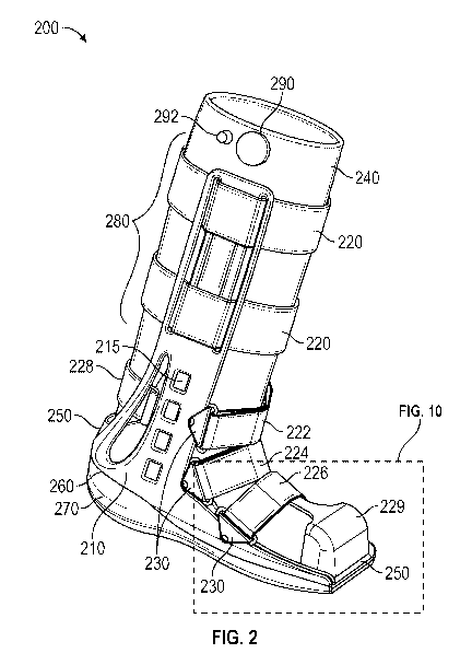
footbed, and a pocket configured to receive the U-shaped malleable stay at an
underside
of the integral portion such that the U-shaped malleable stay extends
underneath the
footbed and through each of the first upright and the second upright.
[0007] According to some embodiments, a method of manufacturing a walking
brace is provided. The method includes providing a U-shaped malleable stay
that is
configured to hold a manually-bent shape. The method includes overmolding an
integral
portion of the walking brace around the U-shaped malleable stay to form a
footbed, a first
upright disposed at a first side of the footbed and a second upright disposed
on a second
side of the footbed such that the U-shaped malleable stay extends through each
of the
footbed, the first upright and the second upright.
[0008] It is understood that various configurations of the subject
technology will
become apparent to those skilled in the art from the disclosure, wherein
various
configurations of the subject technology are shown and described by way of
illustration.
As will be realized, the subject technology is capable of other and different
configurations
and its several details are capable of modification in various other respects,
all without
departing from the scope of the subject technology. Accordingly, the summary,
drawings
and detailed description are to be regarded as illustrative in nature and not
as restrictive.
BRIEF DESCRIPTION OF THE DRAWINGS
[0009] Various embodiments are discussed in detail in conjunction with the
Figures
described below, with an emphasis on highlighting the advantageous features.
These
embodiments are for illustrative purposes only and any scale that may be
illustrated
-2-
CA 03137303 2021-10-18
WO 2020/231663 PCT/US2020/031314
therein does not limit the scope of the technology disclosed. These drawings
include the
following figures, in which like numerals indicate like parts.
[0010] FIG. 1 illustrates a walking brace, in accordance with some example
embodiments;
[0011] FIG. 2 illustrates a perspective view of a walking brace, in
accordance with
some example embodiments;
[0012] FIG 3A illustrates a side view of a short walking brace, in
accordance with
some example embodiments;
[0013] FIG 3B illustrates a side view of a tall walking brace compared to
the walking
brace of FIG. 3A, in accordance with some example embodiments;
[0014] FIG. 4A illustrates front, side and back views of a taller upright
extension for
embodiments of a tall walking brace, in accordance with some embodiments;
[0015] FIG. 4B illustrates front, side and back views of a shorter upright
extension
for embodiments of a short walking brace, in accordance with some embodiments;
[0016] FIG. 4C illustrates fasteners molded into an upright extension, in
accordance with some example embodiments;
[0017] FIG. 4D illustrates the fasteners of FIG. 40 securing a liner
directly to the
upright extension of FIG. 4C, in accordance with some example embodiments;
[0018] FIG. 5 illustrates a perspective cutaway view of at least a portion
of brace
uprights utilizing a single internal U-shaped metallic stay, in accordance
with some
example embodiments;
[0019] FIG. 6 illustrates a perspective view of an alternative mirrored
pair of L-
shaped metallic stays for similar utilization within brace uprights, in
accordance with some
example embodiments;
[0020] FIGs. 7A-70 illustrate an example for installing metallic stays
into a pre-
molded portion of a walking brace, in accordance with some example
embodiments;
[0021] FIG. 8 illustrates a perspective view of gussets for providing
added forward
support to uprights of a walking brace, in accordance with some embodiments;
[0022] FIG. 9 illustrates a side view of the gussets of FIG. 8, in
accordance with
some embodiments;
-3-
CA 03137303 2021-10-18
WO 2020/231663 PCT/US2020/031314
[0023] FIG. 10 illustrates a magnified perspective view of a toe cover for
a walking
brace, in accordance with some example embodiments;
[0024] FIG. 11 illustrates a magnified perspective cutaway view of the toe
cover of
FIG. 10, in accordance with some example embodiments;
[0025] FIG. 12A illustrates a perspective view of at least part of a
molded insole for
a walking brace, in accordance with some example embodiments;
[0026] FIG. 12B illustrates a perspective view of the molded insole of
FIG. 12A
folded into a shape of a heel, in accordance with some embodiments;
[0027] FIG. 13A illustrates a magnified side view of the molded insole of
FIG. 12A
when little to no pressure is applied, in accordance with some embodiments;
[0028] FIG. 13B illustrates a magnified side view of the molded insole of
FIG. 12A
when significant pressure is applied, in accordance with some embodiments;
[0029] FIG. 14A illustrates a front view of a molded insole disposed
within at least
a portion of a walking brace, in accordance with some example embodiments;
[0030] FIG. 14B illustrates a perspective view of the molded insole of
FIG. 14A, in
accordance with some example embodiments;
[0031] FIGs. 15A-15D illustrate an example for installing a molded insole
into a
walking brace, in accordance with some example embodiments;
[0032] FIGs. 16A and 16B illustrate wear patterns and impact damage to an
undersole of a walking brace, in accordance with some example embodiments;
[0033] FIG. 17 illustrates a perspective view of an undersole with an
enhanced
impact region on the heel strike portion of the undersole, in accordance with
some
example embodiments;
[0034] FIG. 18A illustrates a perspective view of a portion of a liner of
a walking
brace including a pump and release valve, in accordance with some example
embodiments;
[0035] FIG. 18B illustrates a cross-sectional view of the liner of FIG.
18B, in
accordance with some example embodiments;
[0036] FIG. 19A illustrates a perspective view of a liner disposed within
a walking
brace, in accordance with some example embodiments;
-4-
CA 03137303 2021-10-18
WO 2020/231663 PCT/US2020/031314
[0037] FIG. 19B illustrates a magnified view of the portion of the liner
and walking
brace in the dotted rectangular box of FIG. 19A;
[0038] FIG. 20A illustrates a schematic view of a liner for a walking
brace, in
accordance with some example embodiments;
[0039] FIG. 20B illustrates several perspective and front schematic views
of the
liner of FIG. 20A;
[0040] FIG. 21 illustrates a perspective view of a pump and release valve
as
disposed within a liner for a walking brace, in accordance with some example
embodiments;
[0041] FIG. 22 illustrates a perspective view of the release valve of FIG.
21;
[0042] FIG. 23A illustrates a side schematic view of the release valve of
FIG. 21;
[0043] FIG. 23B illustrates another side schematic view of the release
valve of FIG.
21 as viewed from the direction denoted "B" in FIG. 23A;
[0044] FIG. 230 illustrates a cross-sectional schematic view of the
release valve
of FIG. 21 as viewed along the cut line denoted C-C' in FIG. 23A;
[0045] FIG. 24 illustrates a conventional chafe;
[0046] FIG. 25 illustrates a walking brace including a plurality of chafe
assemblies,
in accordance with some example embodiments;
[0047] FIG. 26A illustrates a side view of a flexible, rotatable chafe, in
accordance
with some example embodiments;
[0048] FIG. 26B illustrates a top view of the chafe of FIG. 26A from the
vantage
point D-D' in FIG. 26A;
[0049] FIG. 260 illustrates a bottom view of the chafe of FIG. 26A from
the opposite
vantage point compared to FIG. 26B;
[0050] FIG. 26D illustrates a cross-sectional view of the chafe of FIG.
26A taken
along the cut line E-E' in FIG. 260;
[0051] FIG. 27A illustrates a perspective view of a chafe lock, in
accordance with
some example embodiments;
[0052] FIG. 27B illustrates a bottom view of the chafe lock of FIG. 27A;
[0053] FIG. 270 illustrates a side view of the chafe lock of FIG. 27A;
[0054] FIG. 27D illustrates a top view of the chafe lock of FIG. 27A;
-5-
CA 03137303 2021-10-18
WO 2020/231663 PCT/US2020/031314
[0055] FIG. 27E illustrates a cross-sectional view of the chafe lock of
FIG. 27A,
taken along the outline F-F' in FIG. 27D;
[0056] FIG. 28A illustrates installation of a chafe into an aperture of a
walking
brace, in accordance with some example embodiments;
[0057] FIG. 28B illustrates installation of a chafe lock onto a locking
end of the
chafe of FIG. 28A, in accordance with some example embodiments;
[0058] FIG. 280 illustrates securing of the chafe lock and locking end of
the chafe
of FIGs. 28A and 28B into the aperture of the walking brace, in accordance
with some
example embodiments;
[0059] FIG. 28D illustrates the walking brace having a plurality of chafe
assemblies, each comprising the chafe and chafe lock as described in FIGs. 28A-
28C;
[0060] FIGs. 29A and 29B illustrate a flexibility feature of the chafe of
FIGs. 26A-
26D, in accordance with some example embodiments;
[0061] FIGs. 30A-300 illustrate a rotatability feature of the chafe and
chafe lock of
FIGs. 26A-27E, in accordance with some example embodiments;
[0062] FIG. 31A illustrates a perspective view of an alternative walking
brace, in
accordance with some example embodiments;
[0063] FIG. 31B illustrates a side view of the alternative walking brace
of FIG. 31A,
in accordance with some example embodiments;
[0064] FIG. 310 illustrates a footbed profile of the alternative walking
brace of
FIGs. 31A and 31B, in accordance with some example embodiments;
[0065] FIG. 32A illustrates a perspective view of another alternative
walking brace,
in accordance with some example embodiments;
[0066] FIG. 32B illustrates a side view of the alternative walking brace
of FIG. 32A,
in accordance with some example embodiments;
[0067] FIG. 320 illustrates a footbed profile of the alternative walking
brace of
FIGs. 32A and 32B, in accordance with some example embodiments;
[0068] FIG. 33A illustrates a perspective view of yet another alternative
walking
brace, in accordance with some example embodiments;
[0069] FIG. 33B illustrates a side cutaway view of the alternative walking
brace of
FIG. 33A, in accordance with some example embodiments;
-6-
CA 03137303 2021-10-18
WO 2020/231663 PCT/US2020/031314
[0070] FIG. 33C illustrates a footbed profile of the alternative walking
brace of
FIGs. 33A and 33B, in accordance with some example embodiments;
[0071] FIG. 34 illustrates a perspective view of one or more rear straps
of a walking
brace, in accordance with some example embodiments.
DETAILED DESCRIPTION
[0072] The following description and examples illustrate some exemplary
implementations, embodiments, and arrangements of the disclosed invention in
detail.
Those of skill in the art will recognize that there are numerous variations
and modifications
of this invention that are encompassed by its scope. Accordingly, the
description of a
certain example embodiment should not be deemed to limit the scope of the
present
invention.
[0073] Described herein is a walking brace (boot) having a wider foot bed
for
comfort and stability while still providing a relatively low profile. Also
provided is a rocker
bottom which helps to promote natural gait and to reduce plantar pressures.
Cushioned
inner and outer sole afford shock absorption and facilitate patient comfort
during
ambulation. A walking brace disclosed herein can be used in connection with a
stress
fracture of the lower leg, soft tissue injuries, stable fractures and injuries
of the foot and
ankle, bunionectomies, and metatarsal fractures, among other suitable uses.
Moreover,
a walking brace, according to at least some embodiments described herein,
comprise
uprights which can be manually bent to accommodate lower leg anatomy and
bandages.
For example, such a walking brace can include formable uprights which are
advantageously constructed of plastic overmolded onto an aluminum stay.
[0074] FIG. 1 illustrates a walking brace 100, in accordance with some
example
embodiments. Walking brace 100 is illustrated as having two aluminum uprights
110, a
plurality of upright straps 120, a plurality of lower straps (including an
ankle strap 122, a
proximal strap 124, and a distal strap 126), a plurality of chafes 130, a
liner 140, an insole
150, and a boot 160 having an under-boot sole 170. The remaining figures of
this
disclosure illustrate, describe and/or present one or more advancements over
walking
brace 100 of FIG. 1.
[0075] FIG. 2 illustrates a perspective view of a walking brace 200, in
accordance
with some example embodiments. Walking brace 200 is an advancement over
walking
-7-
CA 03137303 2021-10-18
WO 2020/231663 PCT/US2020/031314
brace 100 of FIG. 1. Walking brace 200 comprises a continuous plastic material
that forms
a footbed 260 as well as an upright 210 on either side of brace 200. In some
embodiments, this continuous plastic material is overmolded onto a flexible
aluminum
stay 215. Such a one-piece, continuous plastic overmold eliminates the need
for typical
riveting of formable aluminum upright bars to a rigid plastic boot foot-bed.
[0076] In some embodiments, metallic stay 215 comprises a single, U-shaped
aluminum stay configured to hold its bent form. In such embodiments, metallic
stay 215
is continuous from the left to the right side. In some embodiments, such a "U"
shaped
aluminum stay can be insert-molded into boot footbed 260 at the time of
manufacture
and/or assembly. In some alternative embodiments, such a "U" shaped stay can
be
installed after boot 200 is molded, as illustrated in more detail in
connection with FIGs.
7A-7C. In some other embodiments, stay 215 may comprise two "L" shaped
aluminum
pieces 215a, 215b that face one another, are substantially mirror-versions of
one another,
that can have a gap disposed between one another, and that are configured to
form a
substantial "U" shape, as will be described in more detail in connection with
FIG. 6.
[0077] The formability of uprights 210 by manual application of force to
bend
uprights 210 is a boon to walking brace 200. In application, one has to
balance between
uprights 210 having sufficient stiffness to resist walking forces applied to
brace 200 and
uprights 210 being sufficiently malleable to bend and/or deform sufficiently
to
accommodate lower leg bandaging. Integration of metallic stay(s) 215 with
footbed 260
and uprights 210 allows walking forces on boot 200 to be shared by the plastic
of uprights
210 and metallic stay(s) 215.
[0078] The height, length and/or size of an interchangeable upright
extension(s)
280, one-way snapped into a top of upright(s) 210, at least partially
determine a height of
walking brace 200. Advantageously, walking brace 200 can include a plurality
of such
extensions 280, each of which vary in height according to a desired brace
size. These
sizes can include extra small (XS), small (S), medium (M), large (L) and extra-
large (XL),
each associated with and/or having a corresponding predetermined height,
length and/or
size. For example, FIG 3A illustrates a side view of a short version of
walking brace 200
that utilizes a shorter interchangeable upright extension 380 compared to the
larger
interchangeable upright extension 280 shown in FIGs. 2 and 3B. FIG. 3B also
includes a
-8-
CA 03137303 2021-10-18
WO 2020/231663 PCT/US2020/031314
cutaway plane A-A', which illustrates metallic stay 215, among other features,
in more
detail in FIGs. 3C and 3D.
[0079] Turning back to FIG. 2, walking brace 200 comprises at least one
upright
strap 220, configured to secure a lower leg of a user into brace 200. Upright
strap(s) 220
can couple to and/or be threaded through at least a portion of upright
extension(s)
280,380. For example, in some embodiments that utilize shorter upright
extension 380,
as illustrated in at least FIG. 3A, only one upright strap 220 is coupled
and/or threaded
through at least a portion of shorter upright extension 380. In some other
embodiments
that utilize longer upright extension 280, as illustrated in at least FIGs. 2
and 3B, two or
more upright straps 220 can be coupled and/or threaded through at least a
portion of
longer upright extension 280. However, the present disclosure is not so
limited and any
number of upright straps 220 can be utilized with any-sized upright extension
described
herein.
[0080] Brace 200 further includes a plurality of lower straps, for
example, including
an ankle strap 222 configured to wrap at least partly around and/or against an
ankle of
the user. In some embodiments, the plurality of lower straps includes a
proximal foot strap
224 configured to wrap at least partly around and/or against a proximal
portion of the foot
of the user. In some embodiments, the plurality of lower straps includes a
distal foot strap
226 configured to wrap at least partly around and/or against a portion of the
foot of the
user distal to the proximal portion discussed above.
[0081] In some embodiments, one or more of straps 222, 224, 226 are
configured
to couple to a respective one of a plurality of chafes 230, which are each
configured to
rotatably and/or flexibly secure one side of the respective strap to brace
200. Chafes 230
will be described in more detail in connection with at least FIGs. 25-30C
below.
[0082] In some embodiments, brace 200 further includes a toe cover 229
configured to cover at least one toe of the user. Examples of toe cover 229
will be
described in more detail in connection with at least FIGs. 10 and 11, which
illustrate a
magnified view of toe cover 229 within the dotted rectangular box of FIG. 2.
[0083] Brace 200 may further comprise an insole 250 disposed and
configured to
extend along a length of a top surface of footbed 260. Brace 200 may further
comprise
-9-
CA 03137303 2021-10-18
WO 2020/231663 PCT/US2020/031314
an under-boot sole 270. Examples of under-boot sole 270 will be described in
more detail
in connection with at least FIGs. 16A-17.
[0084] Brace 200 may further comprise a liner 240 comprising a soft,
absorbent
and, in some case, breathable, material configured to support and/or pad a
foot and lower
leg of a user. In some embodiments, liner 240 has an air pump 290, a pressure-
release
valve 292, and one or more air-tight, inflatable cavities (not shown in FIG.
2) disposed
therein such that a desired amount of pressure and/or support can be provided
to one or
more physical locations of the users foot and/or lower leg associated with
each of the one
or more inflatable cavities.
[0085] In some embodiments, a height of liner 240 and/or of its similar
versions
can depend and/or be selected based at least in part on the height of brace
200 and/or a
height of upright extensions 280. For example, FIG. 3A illustrates a liner 340
as having a
first height, as utilized with brace 200 having shorter upright extensions
380, while FIG.
3B illustrates liner 240 having a second height greater than the first height,
as utilized with
brace 200 having longer upright extension 280. Further examples, aspects
and/or
advantages of one or more of liner 240, air pump 290, pressure-release valve
292 and/or
the inflatable cavities are described in more detail in connection with at
least FIGs. 18A-
23C below.
[0086] Discussion will now turn to several aspects of upright extension(s)
280, 380.
FIGs. 4A and 4B illustrate embodiments where strap fasteners 420 are disposed
on
inward- and outward-facing surfaces of upright extensions 380, 280
respectively,
according to some embodiments. For example, each of upright extensions 280,
380 can
comprise a first slot 432 disposed along one edge of upright extensions 280,
380 and a
second slot 434 disposed along an opposite edge of upright extensions 280,
380. Each
of first and second slots 432, 434 are configured to receive one or more of
upright straps
220 and, thereby allow straps 220 to move up and/or down for proper user
support and/or
comfort.
[0087] In addition, each of upright extensions 280, 380 include a stay
pocket 410
configured to receive an end portion of metallic stay 215 from the pocket's
bottom end,
as previously described in connection with at least FIG. 2. In some
embodiments, a one-
way snap feature is further contemplated at a bottom end of either of upright
extensions
-10-
CA 03137303 2021-10-18
WO 2020/231663 PCT/US2020/031314
280, 380 to further secure metallic stay 215 within pocket 410. Having
metallic stay 215
continue into upright extension 280, 380 stiffens the joint between upright
extension 280,
380 and the lower portion of uprights 210.
[0088] As illustrated by FIGs. 4A, 4B, hook-type (or, e.g., complementary
loop-
type) fasteners 420 can be disposed on one or both of inward- (liner-facing)
or outward-
facing surfaces of upright extensions 280, 380. Fasteners 420 are configured
to hold
strap(s) 220 in place on upright extensions 280, 380. In some embodiments,
fasteners
may be Velcro-like. However, the present disclosure is not so limited and
fasteners 420
can comprise any suitable type of fastener(s). In some embodiments, fastener
420 is
disposed on a portion of the outward-facing side of upright extensions 280,
380 medial to
first and second slots 432, 434. In some embodiments, fastener 420 is also
and/or
alternatively disposed on substantially all of the inward-facing side of
upright extensions
280, 380, including the outer portions of first and second slots 432, 434.
[0089] In some embodiments, for example, as illustrated by FIGs. 40 and
4D,
fasteners 420 can be molded into upright extensions 280, 380, rather than
being merely
disposed on a surface of upright extensions 280, 380. In such embodiments,
upright
extensions 280, 380 can be substantially as described in connection with FIGs.
4A and
4B, except that fasteners 420 molded into the inward-facing side of upright
extensions
280, 380 can cover substantially all of the inward-facing side that extends
between the
top and bottom edges of first and second slots 432, 434.
[0090] In some embodiments, fasteners 420 disposed on inward-facing side
of
upright extensions 280, 380 can be configured to not only help hold straps 220
in place
on upright extensions 280, 380 but also directly fasten liner 240 to upright
extensions 280,
380, as illustrated in at least FIG. 4D.
[0091] Turning back to FIGs. 30 and 3D, FIG. 30 illustrates a cutaway view
of
brace 200 as taken along the cutline A-A' in FIG. 3B, while FIG. 3D
illustrates a magnified
view of the portion of FIG. 30 bounded by the dotted rectangular box,
according to some
embodiments. U-shaped metallic stay 215 is illustrated as being disposed at
least partially
within upright 210. At least a terminal portion of metallic stay 215 is
illustrated as
extending beyond the end of upright 210 such that the terminal portion is
configured to
slip into and couple within pocket 410 of upright extension(s) 280, 380. The
magnified
-11-
CA 03137303 2021-10-18
WO 2020/231663 PCT/US2020/031314
view of FIG. 3D further illustrates at least one upright strap 220 disposed at
least along
an outward-facing surface of upright extension 280, 380.
[0092] Turning to FIGs. 5 and 6, FIG. 5 illustrates a perspective cutaway
view of at
least a portion of uprights 210 utilizing a single U-shaped metallic stay 215,
while FIG. 6
illustrates a perspective view of an alternative mirrored pair of L-shaped
metallic stays
215a, 215b for similar utilization within uprights 210, in accordance with
some example
embodiments. As previously described in connection with at least FIG. 2, FIG.
5 shows
use of a single U-shaped metallic stay 215 embedded or after-inserted into
brace 200,
specifically into at least a portion of uprights 210 and such that at least a
terminal portion
at each end of U-shaped metallic stay 215 projects beyond the ends of uprights
210. As
an alternative to single U-shaped metallic stay 215, FIG. 6 shows use of a
mirrored pair
of L-shaped metallic stay 215a, 215b configured to be embedded or after-
inserted into
brace 200, specifically into at least respective portions of uprights 210 and
also such that
at least a terminal portion at of each of L-shaped metallic stay 215a, 215b
projects beyond
the ends of uprights 210. In some such embodiments, a lateral gap 602 is
formed between
the ends of L-shaped metallic stays 215a, 215b opposite to the above-described
terminal
portions. In some embodiments, a width of U-shaped metallic stay 215 and/or of
L-shaped
metallic stays 215a, 215b may gradually decrease toward a top end of the
stay(s). Such
a gradual decrease in width may, in some cases, reduce an amount of stress
exerted on
plastic portions of uprights 210 and/or upright extensions 280.
[0093] FIGs. 7A-7C illustrate several steps of a method of installing
single U-
shaped metallic stay 215 or mirror-paired L-shaped metallic stays 215a, 215b
into at least
a pre-molded portion of brace 200, in accordance with some example
embodiments. For
example, as illustrated in FIG. 7A, single U-shaped stay 215 can be slid into
a pocket
disposed in an underside of a pre-molded portion of brace 200 that includes at
least
uprights 210. Mirror-paired L-shaped metallic stays 215a, 215b could also be
slid into the
same or a similarly-shaped pocket. Once metallic stay(s) 215 or 215a, 215b are
properly
disposed within pre-molded portion of brace 200, under-boot sole 270 is bonded
to the
underside of the pre-molded portion of brace 200 and metallic stay(s) 215 or
215a, 215b,
as illustrated by FIG. 7B, thereby securing metallic stay(s) 215 or 215a, 215b
in place as
illustrated by FIG. 70.
-12-
CA 03137303 2021-10-18
WO 2020/231663 PCT/US2020/031314
[0094] Turning to FIGs. 8 and 9, uprights 210 are designed to be formable
in the
lateral direction but, to support a walking load, uprights 210 should also be
rigid in the
forward/aft direction. To achieve the desired lateral formability and forward
stiffness, a
rear gusset 802 can be molded into, onto, along, and/or as a part of each
upright 210.
Rear gussets 802 add forward support to uprights 210. In some embodiments,
each
gusset 802 extends at an angle from an upper portion of the upright 210,
adjacent to
upright extension 280, 380, to a bottom, posterior edge or portion of upright
210 adjacent
to under-boot sole 270. For example, as shown in at least FIGs. 8 and 9,
gussets 802 can
form a substantially triangular shape or arrangement with uprights 210.
[0095] The above-described arrangement allows gussets 802 to bend in a
lateral
direction along with uprights 210 when uprights 210 are bent in an outward,
lateral
direction as needed to accommodate the fit of the user. However, walking
imposes forces
on brace 200, for example, on uprights 210 and/or upright extensions 280, 380
that cause
tension and/or compression along the direction of extension of gussets 802. In
this way,
suitable stiffness of uprights 210 in the forward/aft direction are achieved.
[0096] Discussion now turns to FIGs. 10 and 11, which illustrate magnified
perspective and cutaway views of protective toe cover 229 of walking brace
200. Toe
cover 229 is advantageously constructed from hard molded plastic. However, the
present
disclosure is not so limited and cover 229 can comprise any suitable material,
including
but not limited to rubber. In some embodiments, toe cover 229 is removable
from brace
200. Toe cover 229 can be secured in place utilizing one or more straps, for
example
hook and loop straps. A first toe cover strap 1002 can couple at least a top
portion of toe
cover 229 to one or both of distal strap 226 and liner 240. A second toe cover
strap 1004
can couple at least a forward portion of toe cover 229 to one or both of
insole 250 and an
underside of liner 240. In some embodiments, utilization of first toe cover
strap 1002
without second toe cover strap 1004 allows toe cover 229 to be removable and
follow
distal strap 226 when it is released. However, toe cover may still be
removable utilizing
both first and second toe cover straps 1002, 1004. While slightly less secure
than an
arrangement utilizing both first and second toe cover straps 1002, 1004, such
a one toe
cover strap arrangement provides a potentially simpler entry and exit to toe
cover 229.
-13-
CA 03137303 2021-10-18
WO 2020/231663 PCT/US2020/031314
[0097] Discussion now turns to insole 205 of FIG. 2. In some embodiments,
insole
205 can be injection molded, compression molded, or cast into an initial
and/or final
shape. In some embodiments, insole 205 is made of foam. However, the present
disclosure is not so limited and insole 205 can be constructed of any suitable
material, for
example and not limitation, a rubber-like material. In some embodiments,
insole 205 can
include air channels, as shown and described in connection with at least FIGs.
12A-13B.
[0098] An issue with body padding, in general, is trapped heat next to the
skin.
Perforations through the padding can help vent trapped heat, but this
technique only
works where the perforations span from the skin to ambient air. When there is
a solid
structure behind the padding preventing a direct air ventilation, conventional
insoles can
become warm to the wearer. Accordingly, one aspect of the present disclosure,
comprises an insole having a waffle-like pattern of raised portions and
venting channels
disposed therebetween, allowing comfortable support to a foot of the user
while also
providing air ventilation along the channels even where conventional padding
perforations
would be presented with an impervious barrier to air ventilation by other,
substantially
solid portions of a brace.
[0099] FIGs. 12A-13B illustrate various perspective and side views of at
least part
of a molded insole for a walking brace, in accordance with some example
embodiments.
In some embodiments, the insole illustrated in FIGs. 12A-13B is at least a
portion of insole
205 of walking brace 200. In some embodiments, as illustrated in FIG. 12A,
insole 205 is
a substantially flat, molded insole comprising a plurality of raised portions
1202 separated
from one another by a plurality of air channels 1204. FIG. 12B illustrates the
portion of
insole 205 of FIG. 12A folded, molded and/or otherwise bent into a shape
configured to
support a heel of the user. In some other embodiments, insole 205 can be
molded directly
into a desired shape, rather than being folded or otherwise bent into its
final shape.
[0100] FIG. 13A illustrates a side view of insole 205 of FIGs. 12A and 12B
having
little or no applied pressure, while FIG. 13B illustrates a side view of
insole 205 having
substantial applied pressure, in accordance with some example embodiments. As
illustrated in FIG. 13A, when little or no pressure is applied to insole 205,
raised portions
1202 and air channels 1204 are in their resting, undistorted shapes. However,
applying
substantial pressure to insole 205 causes raised portions 1202 and air
channels 1204 to
-14-
CA 03137303 2021-10-18
WO 2020/231663 PCT/US2020/031314
distort from their resting shapes, as shown in FIG. 13B. This compression and
release of
insole 205 by a foot of the user forces air through channels 1204 and this
exchanges
humid and hot air, created by the body, with ambient air, thereby cooling the
padding skin
regions.
[0101] FIGs. 14A and 14B illustrate respective front and perspective views
of the
heel section of insole 205 (as previously described in connection with FIGs.
12A-13B)
disposed within a pre-molded portion of brace 200, between uprights 210 and
over
footbed 206. Advantageously, insole 205 is configured to cover an entire area
shown by
the thick line 1402 in FIGs. 14A and 14B. In some embodiments, insole 205 is
adhered
or snapped into the pre-molded portion of brace 200 as shown to secure insole
205 in
place.
[0102] FIGs. 15A-15D illustrate several steps of a method of installing
insole 205
into at least a pre-molded portion of brace 200, in accordance with some
example
embodiments. For example, FIG. 15A illustrates a side view, a perspective view
from
above and a perspective view from below insole 205. In some embodiments,
insole 205
further includes a removable region 1502 where an Achilles tendon of the user
is
configured to rest, as illustrated in at least FIGs. 15A and 15D. As shown in
FIG. 15B,
insole 205 can be inserted and then secured or otherwise bonded to at least a
portion of
footbed 206, as shown in FIG. 15C. In addition, removable region 1502 of
insole 205 can
be cut away to accommodate bandaging and/or access the lower Achilles region
of the
foot of the user.
[0103] Discussion now turns to enhancement of heel strike/impact
absorption of
the brace 200. Typical wear patterns on used boots indicate that the initial
heel strike
occurs at the rear edges of the sole, as indicated by the sole damage shown in
the dotted
rectangular boxes 1602, 1604 in FIGs. 16A, and 16B. Accordingly, to reduce
such heel
strike impacts, under-boot sole 270 comprises an impact absorbing material. In
some
embodiments, a thicker, non-skid material is applied to regions of under-boot
sole 270
corresponding to sole damage regions 1602, 1604 in FIGs. 16A and 16B.
[0104] For example, as illustrated in FIG. 17, under-boot sole 270 can
comprise a
heel strike region 1702 comprising a rubber-like material that is thicker than
at least some
other portions of under-boot sole 270 to absorb the heel strike to the floor
as the user
-15-
CA 03137303 2021-10-18
WO 2020/231663 PCT/US2020/031314
walks. In some embodiments, heel strike region 1702 can comprise an entire
posterior
portion of under-boot sole 270. In some other embodiments, heel strike region
1702 can
comprise a portion that extends along a perimeter and a predetermined distance
toward
a center of such a posterior portion of under-boot sole 270, such that at
least a central
portion of the posterior portion of under-boot sole 270 is not included in the
thicker, heel
strike region 1702. In some embodiments, a surface of at least heel strike
region 1702
can be textured and/or formed from a non-skid material.
[0105] Discussion now turns to liner 240, pump 290 and release valve 292
for
adjusting an amount of pressure and/or support provided by liner 240 and at
least one
inflatable cavity disposed therein. As illustrated in the perspective view of
liner 240 in FIG.
18A and the cross-sectional view of liner 240 in FIG. 18B, liner 240 can
comprise air pump
290, pressure-release valve 292, and one or more air-tight, inflatable
cavities (see FIGs.
19A and 20A) in fluid communication with air pump 290 and pressure-release
valve 292
such that a desired, adjustable amount of pressure and/or support can be
provided to one
or more physical locations of the user's foot and/or lower leg associated with
each of the
one or more inflatable cavities.
[0106] As illustrated in FIGs. 18A and 18B, pump 290 and release valve 292
can
be disposed within, and sufficiently close to an upper edge of, liner 240 such
that the user
can easily and comfortably adjust an amount of inflation of one or more
inflatable cavities
within liner 240 by pushing on the pump 290 and/or release valve 292 from the
outside of
the liner. Another advantage of positioning pump 290 and release valve 292
sufficiently
close to the upper edge of liner 240 is that the user can alternatively pinch
the pump bulb
by simultaneously applying pressure from the outside and from the inside of
liner 240.
Such a pinch-actuation of pump 290 and/or of release valve 292 allows the use
of hand
strength to directly affect actuation, rather than relying on, typically,
weaker arm strength
when activation is affected at the length of a partially extended arm. By
contrast, pumps
and/or release valves disposed farther down a brace and/or liner than the
inside length
of a user's thumb, for example, would not allow for such alternative pinch-
actuation of
such a pump and/or release valve.
[0107] FIG. 19A illustrates liner 240, as described above and further
illustrating the
least one inflatable cavity 1902, where liner 240 is disposed within brace
200. FIG. 19B
-16-
CA 03137303 2021-10-18
WO 2020/231663 PCT/US2020/031314
provides a magnified view of the dotted rectangular box portion of FIG. 19A.
As illustrated,
pump 290 is in fluid communication with release valve 292. One or both of pump
290 and
release valve 292 are also in fluid communication with inflatable cavity 1902,
disposed
within liner 240. In some embodiments, inflatable cavity 1902 may be disposed
in portion
of liner 240 configured to abut a portion of the user's foot. However, the
present disclosure
is not so limited and any number of inflatable cavities may be utilized and
such inflatable
cavities can be disposed within any suitable portion of liner 240.
[0108] FIG. 20A illustrates a flattened schematic view of liner 240 that
shows an
example orientation of pump 290, release valve 292 and at least one inflatable
cavity
1902. FIG. 20B illustrates a front and several perspective schematic views of
liner 240 as
illustrated in FIG. 20A. As shown, pump 290 is in fluid communication with
release valve
292 and release valve 292 is in fluid communication with inflatable cavity
1902 through a
tube 2002. In FIG. 20A, inflatable cavity 1902 is illustrated as extending
substantially
along and within portions of liner 240 configured to abut medial and lateral
sides of a foot
of a user, as well as at least a portion of the user's ankle, but in some
embodiments also
a portion of the lower calf of the user. In some embodiments, inflatable
cavity 1902 is
disposed symmetrically within liner 240 such that a portion of inflatable
cavity 1902
extending to one side of a vertical centerline of liner 240 is a substantial
mirror image of
a portion of inflatable cavity 1902 extending to the other side of the
vertical centerline.
However, the present disclosure is not so limited and inflatable cavity 1902
and/or any
other inflatable cavity can be disposed in any other suitable portion of liner
240 and with
any suitable orientation.
[0109] Discussion will now turn to a protective rim disposed around a
perimeter of
release valve 292 and configured to prevent accidental or inadvertent
deflation of the one
or more inflatable cavities 1902 of liner 240, in connection with at least
FIGs. 21-23C.
[0110] Inadvertent deflation of inflatable cavities 1902 of liner 240 of
walking brace
200 can cause discomfort and possible body fluid "puddling" around and below
an injury.
Inflatable cavities 1902 aid in providing comfort and mitigating such body
fluid "puddling".
Such inflatable cavities 1902 are inflated manually utilizing pump 290, which
can be a
bulb-like hand pump. Air and/or other fluid can be released from inflatable
cavities 1902
utilizing release valve 292, which can comprise a push-button actuated valve.
Such push
-17-
CA 03137303 2021-10-18
WO 2020/231663 PCT/US2020/031314
buttons are easy to use and are less likely to leak or sustain damage from
over rotating,
as can more commonly happen when using a twisting, knob-type release valve.
However, such push button type release valves can be prone to accidental
activation.
[0111] The most popular method to prevent accidental pushing of a release
button
is to provide a protective cap that covers the button. While functional, such
protective
caps add cost and complexity to the release valves. Moreover, protective caps
can be
broken off or damaged. By contrast, a protective rim made a part of the
release valve
structure is static, does not move or flex, and is not easily damaged.
[0112] Accordingly, to prevent accidental release of air or other fluid
from Inflatable
cavities 1902, release valve 292 can further include a crenulated type rim
2102, as
illustrated in at least FIGs. 21 and 23C. FIG. 22 further illustrates a
magnified view of rim
2102 and release valve 292, while FIGs. 23A-23C illustrate several side and
cutaway
views of pump 290, release valve 292 and/or rim 2102.
[0113] Rim 2102 can extend along substantially an entire perimeter of
release
valve 292 button and can also extend to a height slightly greater than a top
or outside
surface of the release valve 292 button, for example and not limitation 0.02
inches (0.5
millimeters) above the top or outside surface of release valve 292 button.
Further, in some
embodiments as illustrated in at least FIG. 230, the release valve 292 button
can have a
substantially concave shape, providing tactile feedback as to the location of
the center of
the release valve 292 button.
[0114] Discussion will now turn to chafe and chafe lock features
configured to allow
a chafe to align with a direction of pull of one or more straps of a walking
brace, such as
brace 200.
[0115] FIG. 24 illustrates a top view of a conventional chafe 2400. Chafe
2400 is
an assembly comprising an attachment feature, also called a chape 2404, and a
metal or
plastic loop 2402 coupled thereto. Loop 2402 is configured to accommodate
securing of
a strap or a webbing. Chapes, or "caps" of various designs can be fitted to
such a loop
and are typically fabricated in the form of a plate, for example for
utilization in a belt, as a
belt buckle. However, conventional chafes 2400 are typically riveted to an
item needing
securing and are not configured to rotate, hinge, bend or otherwise flex and,
so, are not
configured to align with a direction of pull of one or more straps coupled to
loop 2402.
-18-
CA 03137303 2021-10-18
WO 2020/231663 PCT/US2020/031314
Accordingly, such conventional chafes 2400 cannot tightly bind, for example, a
narrow
leg into a walking brace, for example walking brace 200.
[0116] The present disclosure contemplates an alternative chafe assembly,
comprising a chafe and a chafe lock that, together, allow the chafe to align
with the
direction of pull of a strap coupled to a loop of the chafe. Installation of
such a chafe
assembly requires no tools, is completely manual and, once the chafe is
secured to its
lock, the lock is configured to spin within its mounting aperture, which
prevents a hinge
region of the chafe from twisting while still allowing the chafe to bend and
align with the
direction of pull of a strap coupled to a loop of the chafe.
[0117] FIG. 25 illustrates walking brace 200 having a plurality of
rotatable chafe
assemblies 2500 for securing one or more straps of brace 200, in accordance
with some
example embodiments. Chafe assembly 2500 comprises a chafe 2600, for example
as
described in more detail in connection with at least FIGs. 26A-26D, and a
chafe lock 2700,
for example as described in more detail in connection with at least FIGs. 27A-
27E.
Discussion now turns to chafe 2600 in connection with FIGs. 26A-26D.
[0118] FIG. 26A illustrates a side view of chafe 2600, in accordance with
some
example embodiments. FIG. 26B illustrates a top view of chafe 2600 viewed from
the
vantage point D-D' in FIG. 26A. FIG. 26C illustrates a bottom view of chafe
2600 viewed
from the opposite vantage point as FIG. 26B. And FIG. 26D illustrates a cross-
sectional
view of chafe 2600 viewed along the cut-line E-E' in FIG. 26C. While several
example
dimensions will be described regarding certain aspects of chafe 2600, the
present
disclosure also contemplates chafe 2600 having any other suitable dimensions
and/or
construction.
[0119] Chafe 2600 comprises a head 2602, a neck 2604 and a locking end
2606.
Head 2602 comprises a slot 2608 configured for receiving, for example, any of
straps
222, 224, 226. In some embodiments, slot 2608 has a width wi of approximately
1.5
inches and a length Li of approximately 0.216 inches. However, as stated
above, other
widths are also contemplated, for example and not limitation, 2 inches. In
some
embodiments, a distal wall of slot 2608 is formed at a substantially 90 angle
with respect
to a top surface of head 2602 and may have a radius of curvature ri of
approximately
0.06 inches therebetween. In some embodiments, the distal wall of slot 2608
may
-19-
CA 03137303 2021-10-18
WO 2020/231663 PCT/US2020/031314
transition to the substantially perpendicular orientation of an adjacent
sidewall along the
Li lengthwise direction with a radius of curvature r8 of approximately 0.02
inches. In some
embodiments, a proximal wall of slot 2608 is formed at a substantially 45
angle with
respect to a top surface of head 2602 and may have a radius of curvature r2
therebetween
of approximately 0.02 inches. Furthermore, in some embodiments, a sidewall of
head
2602 may have a thickness of 0.23 inches, as measured along the width-wise
(wi)
direction between slot 2608 and a lateral outside edge of head 2602.
[0120] In some embodiments, head 2602 may transition to neck 2604 by
narrowing
to a width w2 of, for example, 0.3 inches, and a thickness T2 of, for example,
0.04 to 0.05
inches. In some embodiments, the first transition from head 2602 to neck 2604
may follow
a radius of curvature r3 of, for example, 0.1 inches, as measured at a
backside of the
transition, and neck 2604 may extend away from head 2602 at an angle of, for
example,
30 relative to the top surface of head 2602. In some embodiments, neck 2604
may
extend from the first transition for a length L2 of approximately 0.451 inches
and then
transition, again, bending, for example, approximately another 90 from neck
2604 to
locking end 2606 along a radius of curvature r4 of, for example, 0.1 inches,
as measured
at a backside of the second transition. The relative thinness of neck 2604,
especially at
and adjacent to the portion at radius of curvature r4, allows sufficient
flexing and/or
bending of neck 2604 such that chafe 2600 extends substantially in the
direction of
tension imposed by a strap coupled within slot 2608, thereby allowing a more
secure fit
of walking brace 200.
[0121] In some embodiments, locking end 2606 comprises a substantially
cylindrical feature having a substantially ovoid or elliptical cross-section.
In some such
embodiments, the substantially cylindrical feature of locking end 2606 may
have a major
diameter Di of, for example, 0.11 0.003 inches, a minor diameter D2 of, for
example,
0.063 0.003 inches and may be offset from a backside surface of neck 2604 by a
distance
di of, for example, 0.135 inches. Accordingly, the substantially cylindrical
feature may
have various radii of curvature along the different portions of its surface.
For example, a
radius of curvature r5 along a portion extending along the major diameter Di
may be, for
example, 0.065 inches, a radius of curvature r6 along a portion extending
along the minor
diameter D2 may be, for example, 0.025 inches, and a radius of curvature r7 at
a transition
-20-
CA 03137303 2021-10-18
WO 2020/231663 PCT/US2020/031314
between the substantially cylindrical feature and neck 2604 may be, for
example, 0.01
inches. This substantially cylindrical feature is configured to slide into a
slot of chafe lock
2700 as will be described in more detail in connection with FIGs. 27A-27E.
[0122] FIG. 27A illustrates a perspective view of chafe lock 2700, in
accordance
with some example embodiments. FIG. 27B illustrates a bottom view of chafe
lock 2700.
FIG. 270 illustrates a side view of chafe lock 2700. FIG. 27D illustrates a
top view of chafe
lock 2700. And FIG. 27E illustrates a cross-sectional view of chafe lock 2700
viewed
along the cut-line F-F' in FIG. 27D.
[0123] Chafe lock 2700 comprises a cap 2702, a slot 2704 disposed
underneath
cap 2702 and a plurality of snap clips 2706 disposed underneath cap 2702 and
slot 2704.
Slot 2604 is configured to receive locking end 2606 of chafe 2600,
specifically the
substantially cylindrical feature having the substantially ovoid or elliptical
cross-section
described above, by sliding laterally over locking end 2606 such that the
substantially
cylindrical feature is secured within slot 2604. An underside of cap 2702 is
configured to
abut a first side of an aperture within walking brace 200, while the plurality
of snap clips
2706 are configured to extend through and snap around a second side of the
aperture,
thereby securing chafe lock 2700 within the aperture while also allowing chafe
lock 2700,
and attached chafe 2600, to rotate freely within the aperture. In some
embodiments, the
aperture, chafe lock 2700 and/or chafe 2600 may be configured such that chafe
lock 2700
and attached chafe 2600 are configured to rotate freely within a
predetermined, desired
range of rotation within the aperture and prevented from rotating beyond or
outside that
predetermined, desired range of rotation. In some embodiments, such a desired
range of
rotation would allow chafe 2600 to always point substantially in a desired
direction and/or
orientation with respect to the aperture, increasing user convenience. While
several
example dimensions will be described regarding certain aspects of chafe lock
2700, the
present disclosure also contemplates chafe lock 2700 having any other suitable
dimensions and/or construction.
[0124] Cap 2702 can have a substantially circular shape and may have a
diameter
D3 of, for example, 0.445 inches, and a thickness T3 of, for example,
approximately 0.09
inches. In some embodiments, cap 2702 has a convex upper surface having a
major
-21-
CA 03137303 2021-10-18
WO 2020/231663 PCT/US2020/031314
radius of curvature r9 of, for example, 0.639 inches and a minor radius of
curvature no of,
for example, 0.03 inches at its edges.
[0125] In some embodiments, slot 2704 has an internal depth d2 of, for
example,
0.068 0.003 inches, an internal width w3 of, for example, 0.115 0.003 inches,
and an
opening width w4 of, for example 0.05 0.003 inches. Opening width w4 being
narrower
than internal width w3 allows slot 2704 to receive and retain locking end 2606
of chafe
2600. In some embodiments, the opening of slot 2704 may have a radius of
curvature r12
at its top edge of, for example, 0.008 inches and a radius of curvature ri3 at
its bottom
edge of, for example, 0.002 inches. In some embodiments, sidewalls of slot
2704 may
have a thickness T4 of, for example, 0.04 inches and a radius of curvature ri
1
therebetween of, for example, 0.028 inches.
[0126] In some embodiments, the plurality of snap clips 2706 may have a
substantially circular or cylindrical shape, substantially centered about a
centerline of cap
2702. In some embodiments, snap clips 2706 may have an outer circular diameter
D4 of,
for example, 0.353 0.003 inches, and may further comprise protrusions with a
beveled
lower edge that extends outward from the outer circular diameter by a distance
d3 of, for
example, 0.02 0.003 inches. A distance d4 between an underside of cap 2702 and
a top
side of these protrusions may be slightly larger than a depth or thickness of
the aperture
in brace 200 in which chafe lock 2700 is configured to be secured, for
example,
0.19 0.005 inches. Accordingly, snap clips 2706 may have a thickness suitable
to allow
them to deflect slightly when pushed into the aperture of brace 200 but to
snap back to
their original shape and orientation once the protrusions clear the backside
of the
aperture, thereby rotatably securing chafe lock 2700 in the aperture.
[0127] An example method of securing the chafe 2600 and chafe lock 2700 in
an
aperture of walking brace 200 will now be described in connection with FIGs.
28A-28D.
As illustrated in FIG. 28A, locking end 2606 of chafe 2600 is pushed through
aperture
2802 of walking brace 200. In some embodiments, aperture(s) 2802 of walking
brace 200
may be disposed in uprights 210. As illustrated in FIG. 28B, chafe lock 2700
is slid onto
the portion of locking end 2606 of chafe 2600 protruding through aperture
2802.
Specifically, the substantially cylindrical feature of locking end 2606 is
slid laterally into
slot 2704 of chafe lock 2700. As illustrated in FIG. 28C, chafe 2600 is pulled
back away
-22-
CA 03137303 2021-10-18
WO 2020/231663 PCT/US2020/031314
from aperture 2802 such that chafe lock 2700 is pulled into and rotatably
secured within
aperture 2802. Specifically, by pulling head 2602 of chafe 2600 away from
aperture 2802,
an underside of cap 2702 of chafe lock 2700 is brought into direct contact
with at least a
proximal portion of aperture 2802 and the protrusions of the plurality of snap
clips 2706
snap into place around a backside of aperture 2802, thereby rotatably securing
chafe lock
2700 within aperture 2802. FIG. 28D illustrates a plurality of chafe
assemblies, each
including a chafe 2600 and chafe lock 2700 rotatably secured in a respective
aperture of
walking brace 200, substantially as described above.
[0128] As illustrated in FIGs. 29A and 29B, chafe 2600 is configured to
flex or bend
to varying degrees and extend substantially in a direction of a tension
exerted on chafe
2600 by a strap coupled to head 2602. This flexibility is provided, at least
in part, by the
relative narrowness of neck 2604 of chafe 2600 as described above.
[0129] Moreover, as illustrated in FIGs. 30A-30C, chafe 2600 and chafe
lock 2700
are further configured to rotate while secured within aperture 2802 by virtue,
at least, of
locking end 2606 of chafe 2600 being secured within slot 2704 of chafe lock
2700 and
chafe lock 2700 being rotatably secured within aperture 2802. Specifically, an
underside
of cap 2702 of chafe lock 2700 is in direct physical contact with a proximal
edge of
aperture 2802 and the protrusions of snap clips 2706 are snapped into place
around a
backside of aperture 2802. Moreover, locking end 2606 of chafe 2600 is
prevented from
sliding out of slot 2704 of chafe lock 2700 at least by the sidewalls of
aperture 2802
blocking slot 2704.
[0130] Modifications to the aforementioned embodiments are likewise
contemplated. The walking brace may be secured to the limb of a wearer using
one of
three alternative configurations. Any combination of features described
anywhere in this
disclosure are also contemplated.
[0131] FIGs. 31A-31C illustrate a first additional and/or alternative
configuration for
a walking brace, in accordance with some example embodiments. For example,
FIG. 31A
illustrates a perspective view of a walking brace 3100, in accordance with
some example
embodiments. FIG. 31B illustrates a side view of brace 3100 of FIG. 31A, in
accordance
with some example embodiments. And FIG. 31C illustrates a top view of a
footbed profile
of brace 3100 of FIG. 31A, in accordance with some example embodiments.
-23-
CA 03137303 2021-10-18
WO 2020/231663 PCT/US2020/031314
[0132] Walking brace 3100 comprises a continuous plastic, EVA or other
suitable
material that forms a footbed 3160, outer sole 3170 and an upright 3110 on
either side of
brace 3100 overmolded onto a semi-rigid metallic or plastic stay 3115. In some
embodiments, outer sole 3170 is non-slip, comprising a tread pattern formed in
the EVA
foam. Alternatively, a non-slip tread can be adhered to outer sole 3170. Such
a one-
piece, continuous plastic overmold eliminates the need for typical riveting of
formable
aluminum upright bars to a rigid plastic boot foot-bed. Integration of
metallic stay(s) 3115
with footbed 3160 and uprights 3110 allows walking forces on boot 3100 to be
shared by
the plastic of uprights 3110 and metallic stay(s) 3115. In some embodiments,
metallic
stay(s)/bar(s) 2115 can comprise annealed aluminum. However, the present
disclosure
is not so limited and any suitable metallic and/or semi-rigid plastic material
is also
contemplated. As illustrated in FIGs. 31A and 31B, the overmold material also
forms an
integral toe cover 229 and an integral heel cover 3102, one or both of which
can provide
"bump" protection. In some embodiments, toe cover 3129 and heel cover 3102 can
be
removed by cutting, unattaching and/or otherwise tearing one or both off.
[0133] Walking brace 3100 comprises at least one upright strap 3120,
configured
to secure a lower leg of a user into brace 3100. Upright strap(s) 3120 can
couple to and/or
be threaded through at least a portion of upright 3110. In some embodiments,
two or more
upright straps 3120 can be coupled and/or threaded through at least a portion
of upright
extension 3110. As illustrated in FIG. 31A, walking brace 3100 does not
include any
hook/loop strips or fasteners on an inside surface of uprights 3110.
[0134] Brace 3100 further includes a plurality of lower straps, for
example,
including a proximal foot strap 3124 configured to wrap at least partly around
and/or
against a proximal portion of the foot of the user. In some embodiments, the
plurality of
lower straps includes a distal foot strap 3126 configured to wrap at least
partly around
and/or against a portion of the foot of the user distal to the proximal
portion discussed
above.
[0135] In some embodiments, one or more of straps 3124, 3126 are
configured to
couple to a respective one of a plurality of chafes 3130, which are each
configured to
rotatably and/or flexibly secure one side of the respective strap to brace
3100. Chafes
3130 can be as described in connection with any chafe in this disclosure.
Alternatively,
-24-
CA 03137303 2021-10-18
WO 2020/231663 PCT/US2020/031314
chafes 3130 can comprise D-rings molded into brace 3100, while still retaining
sufficient
flexibility to bend in a direction of tension exerted by one or more straps
coupled thereto.
[0136] Brace 3100 may further comprise a liner 3140 comprising a soft,
absorbent
and, in some case, breathable, material configured to support and/or pad a
foot and lower
leg of a user. Liner 3140 can comprise any liner as previously described
anywhere in this
disclosure.
[0137] FIGs. 32A-32C illustrate a second additional and/or alternative
configuration for a walking brace, in accordance with some example
embodiments. For
example, FIG. 32A illustrates a perspective view of a walking brace 3200, in
accordance
with some example embodiments. FIG. 32B illustrates a side view of brace 3200
of FIG.
32A, in accordance with some example embodiments. And FIG. 32C illustrates a
top view
of a footbed 3260 profile of brace 3200 of FIG. 32A, in accordance with some
example
embodiments.
[0138] Walking brace 3200 comprises a continuous plastic, EVA or other
suitable
material that forms a footbed 3260, inner sole 3250, outer sole 3270 and an
upright 3210
on either side of brace 3200 overmolded onto a semi-rigid metallic or plastic
stay 3215
that spans the ankle portion of walking brace 3200, for example, rather than
extending
substantially an entire height of walking brace 3200. In some embodiments,
outer sole
3270 is non-slip, comprising a tread pattern formed in the EVA foam.
Alternatively, a non-
slip tread can be adhered to outer sole 3270. Such a one-piece, continuous
plastic
overmold eliminates the need for typical riveting of formable aluminum upright
bars to a
rigid plastic boot foot-bed. Integration of metallic stay(s) 3215 with footbed
3260 and
uprights 3210 allows walking forces on boot 3200 to be shared by the plastic
of uprights
3210 and metallic stay(s) 3215. As illustrated in FIGs. 32A and 32B, the
overmold material
also forms a triangular or triangulated framing 3275 to further increase
rigidity in the
forward/backward direction, an integral toe cover 229 and an integral heel
cover 3202,
one or both covers providing "bump" protection. In some embodiments, toe cover
3229
and heel cover 3202 can be removed by cutting, unattaching and/or otherwise
tearing
one or both off.
[0139] Walking brace 3200 can further comprise upright extensions 3280,
which
may be similar to upright extensions 280, 380 as previously described. As
illustrated,
-25-
CA 03137303 2021-10-18
WO 2020/231663 PCT/US2020/031314
upright extension 3280, uprights 3210 and/or triangular frame 3275 can further
comprise
one or more flexible/rotatable chafes 3230, as described in connection with
any chafe in
this disclosure, or alternatively, molded-in D-rings that still retain
sufficient flexibility to
bend in a direction of tension exerted by one or more straps coupled thereto.
[0140] Walking brace 3200 comprises at least one upright strap 3220,
configured
to secure a lower leg of a user into brace 3200 and at least one lower strap,
for example,
a foot strap 3226 configured to wrap at least partly around and/or against a
portion of the
foot of the user. Straps 3220, 3226 are configured to coupled to chafes and/or
molded-in
D-rings 3230.
[0141] Brace 3200 may further comprise a liner 3240 comprising a soft,
absorbent
and, in some case, breathable, material configured to support and/or pad a
foot and lower
leg of a user. Liner 3240 can comprise any liner as previously described
anywhere in this
disclosure.
[0142] FIGs. 33A-33C and FIG. 34 illustrate a third additional and/or
alternative
configuration for a walking brace, in accordance with some example
embodiments. For
example, FIG. 33A illustrates a perspective view of a walking brace 3300, in
accordance
with some example embodiments. FIG. 33B illustrates a side cutaway view of
brace 3300
of FIG. 33A, in accordance with some example embodiments. FIG. 330 illustrates
a top
view of a footbed 3360 profile of brace 3300 of FIG. 33A, in accordance with
some
example embodiments. And FIG. 34 illustrates a perspective view of one or more
rear
straps of walking brace 3300, in accordance with some example embodiments.
[0143] Walking brace 3300 comprises a continuous plastic, EVA or other
suitable
material that forms a footbed 3360, inner sole 3350, outer sole 3370 and an
upright 3310
on either side of brace 3300 overmolded onto a semi-rigid metallic or plastic
structure
3315 that extends substantially an entire height of walking brace 3300. In
some
embodiments, the overmold material further comprises an integral toe cover
3329 and an
integral heel cover 3302, one or both covers providing "bump" protection. In
some
embodiments, toe cover 3329 and heel cover 3302 can be removed by cutting,
unattaching and/or otherwise tearing one or both off. In some embodiments,
outer sole
3370 is non-slip, comprising a tread pattern formed in the EVA foam.
Alternatively, a non-
slip tread can be adhered to outer sole 3370.
-26-
CA 03137303 2021-10-18
WO 2020/231663 PCT/US2020/031314
[0144] As illustrated, metallic and/or plastic structure 3315 includes a
triangular
frame 3375 disposed at an ankle region. Triangular frame 3375 may have
substantially
the same function as previously described triangular frame 3275. Metallic
and/or plastic
structure 3315 further comprises one or more molded-in D-rings that act as
living hinges
and retain sufficient flexibility to bend in a direction of tension exerted by
one or more
straps coupled thereto. Such a one-piece, continuous plastic overmold
eliminates the
need for typical riveting of formable aluminum upright bars or D-rings to a
rigid plastic
boot frame. Integration of metallic structure 3315 with footbed 3360 and
uprights 3310
allows walking forces on boot 3300 to be shared by the plastic of uprights
3310 and
metallic stay(s) 3315. As illustrated in FIGs. 33A and 33B, the metallic
and/or plastic
structure 3315 is further supported by a metallic insert 3318 disposed along
the ankle
region of brace 3300 and configured to increase rigidity in the
forward/backward direction.
[0145] In some embodiments, brace 3300 further includes upright extensions
3380, which themselves may also include a portion of metallic and/or plastic
structure
3315 that further comprises one or more molded-in D-rings that also act as
living hinges
and retain sufficient flexibility to bend in a direction of tension exerted by
one or more
straps coupled thereto. Advantageously, utilization of uprights 3380 or not
provides brace
3300 with two heights. A lower, base height may utilize brace 3300 without
upright
extension(s) 3380, while a greater height can be had by utilizing upright
extensions 3380.
In some embodiments, upright extension(s) 3380 can be snapped into upright(s)
3310.
However, the present disclosure is not so limited and any method of attachment
between
upright extensions 3380 and uprights 3310 is also contemplated.
[0146] Walking brace 3300 comprises a plurality of straps 3320, configured
to
couple to molded-in D-rings 3330 of one or both of uprights 3310 and upright
extensions
3380, wrap around a front side of brace 3300 and secure a lower leg of a user
into brace
3300. The overmold of uprights 3310 and/or of upright extensions 3380 further
comprises
at least one rear strap that is configured to wrap around a backside of the
lower leg of the
user and secure the lower leg of the user into the brace 3300 from the
backside. In some
embodiments, rear straps 3312 can comprise a fastener, for example a hook and
loop
fastener. In some embodiments, as further illustrated in FIG. 34, rear straps
3312 of brace
3300 comprise a plurality of holes 3402 configured to be stretched over a
plastic
-27-
CA 03137303 2021-10-18
WO 2020/231663 PCT/US2020/031314
"mushroom" shaped post 3404 secured to upright 3310 and/or to upright
extension 3380
to thereby secure the lower leg of the user into the brace 3300 from the
backside.
[0147] Implementations of the technology described herein are directed
generally
to a walking boot having a variety of unique features. To facilitate an
understanding of the
various embodiments described herein, a number of terms are further defined
below.
General Interpretive Principles for the Present Disclosure
[0148] Various aspects of the novel systems, apparatuses, and methods are
described more fully hereinafter with reference to the accompanying drawings.
The
teachings disclosure may, however, be embodied in many different forms and
should not
be construed as limited to any specific structure or function presented
throughout this
disclosure. Rather, these aspects are provided so that this disclosure will be
thorough
and complete, and will fully convey the scope of the disclosure to those
skilled in the art.
Based on the teachings herein one skilled in the art should appreciate that
the scope of
the disclosure is intended to cover any aspect of the novel systems,
apparatuses, and
methods disclosed herein, whether implemented independently of or combined
with any
other aspect of the disclosure. For example, a system or an apparatus may be
implemented, or a method may be practiced using any one or more of the aspects
set
forth herein. In addition, the scope of the disclosure is intended to cover
such a system,
apparatus or method which is practiced using other structure, functionality,
or structure
and functionality in addition to or other than the various aspects of the
disclosure set forth
herein. It should be understood that any aspect disclosed herein may be set
forth in one
or more elements of a claim. Although some benefits and advantages of the
preferred
aspects are mentioned, the scope of the disclosure is not intended to be
limited to
particular benefits, uses, or objectives. The detailed description and
drawings are merely
illustrative of the disclosure rather than limiting, the scope of the
disclosure being defined
by the appended claims and equivalents thereof.
[0149] With respect to the use of plural vs. singular terms herein, those
having skill
in the art can translate from the plural to the singular and/or from the
singular to the plural
as is appropriate to the context and/or application. The various
singular/plural
permutations may be expressly set forth herein for sake of clarity.
-28-
CA 03137303 2021-10-18
WO 2020/231663 PCT/US2020/031314
[0150] When describing an absolute value of a characteristic or property
of a thing
or act described herein, the terms "substantial," "substantially,"
"essentially,"
"approximately," and/or other terms or phrases of degree may be used without
the specific
recitation of a numerical range. When applied to a characteristic or property
of a thing or
act described herein, these terms refer to a range of the characteristic or
property that is
consistent with providing a desired function associated with that
characteristic or property.
[0151] In those cases where a single numerical value is given for a
characteristic
or property, it is intended to be interpreted as at least covering deviations
of that value
within one significant digit of the numerical value given.
[0152] If a numerical value or range of numerical values is provided to
define a
characteristic or property of a thing or act described herein, whether or not
the value or
range is qualified with a term of degree, a specific method of measuring the
characteristic
or property may be defined herein as well. In the event no specific method of
measuring
the characteristic or property is defined herein, and there are different
generally accepted
methods of measurement for the characteristic or property, then the
measurement
method should be interpreted as the method of measurement that would most
likely be
adopted by one of ordinary skill in the art given the description and context
of the
characteristic or property. In the further event there is more than one method
of
measurement that is equally likely to be adopted by one of ordinary skill in
the art to
measure the characteristic or property, the value or range of values should be
interpreted
as being met regardless of which method of measurement is chosen.
[0153] It will be understood by those within the art that terms used
herein, and
especially in the appended claims (e.g., bodies of the appended claims) are
intended as
"open" terms unless specifically indicated otherwise (e.g., the term
"including" should be
interpreted as "including but not limited to," the term "having" should be
interpreted as
"having at least," the term "includes" should be interpreted as "includes but
is not limited
to," etc.).
[0154] It will be further understood by those within the art that if a
specific number
of an introduced claim recitation is intended, such an intent will be
explicitly recited in the
claim, and in the absence of such recitation no such intent is present. For
example, as an
aid to understanding, the following appended claims may contain usage of the
-29-
CA 03137303 2021-10-18
WO 2020/231663 PCT/US2020/031314
introductory phrases "at least one" and "one or more" to introduce claim
recitations.
However, the use of such phrases should not be construed to imply that the
introduction
of a claim recitation by the indefinite articles "a" or "an" limits any
particular claim
containing such introduced claim recitation to embodiments containing only one
such
recitation, even when the same claim includes the introductory phrases "one or
more" or
"at least one" and indefinite articles such as "a" or "an" (e.g., "a" and/or
"an" should
typically be interpreted to mean "at least one" or "one or more"); the same
holds true for
the use of definite articles used to introduce claim recitations. In addition,
even if a specific
number of an introduced claim recitation is explicitly recited, those skilled
in the art will
recognize that such recitation should typically be interpreted to mean at
least the recited
number (e.g., the bare recitation of "two recitations," without other
modifiers, typically
means at least two recitations, or two or more recitations).
[0155] In those instances where a convention analogous to "at least one of
A, B,
and C" is used, such a construction would include systems that have A alone, B
alone, C
alone, A and B together without C, A and C together without B, B and C
together without
A, as well as A, B, and C together. It will be further understood by those
within the art
that virtually any disjunctive word and/or phrase presenting two or more
alternative terms,
whether in the description, claims, or drawings, should be understood to
contemplate the
possibilities of including one of the terms, either of the terms, or both
terms. For example,
the phrase "A or B" will be understood to include A without B, B without A, as
well as A
and B together."
[0156] Various modifications to the implementations described in this
disclosure
can be readily apparent to those skilled in the art, and generic principles
defined herein
can be applied to other implementations without departing from the spirit or
scope of this
disclosure. Thus, the disclosure is not intended to be limited to the
implementations
shown herein but is to be accorded the widest scope consistent with the
claims, the
principles and the novel features disclosed herein. The word "exemplary" is
used
exclusively herein to mean "serving as an example, instance, or illustration."
Any
implementation described herein as "exemplary" is not necessarily to be
construed as
preferred or advantageous over other implementations.
-30-
CA 03137303 2021-10-18
WO 2020/231663 PCT/US2020/031314
[0157] Certain features that are described in this specification in the
context of
separate implementations also can be implemented in combination in a single
implementation. Conversely, various features that are described in the context
of a single
implementation also can be implemented in multiple implementations separately
or in any
suitable sub-combination. Moreover, although features can be described above
as acting
in certain combinations and even initially claimed as such, one or more
features from a
claimed combination can in some cases be excised from the combination, and the
claimed combination can be directed to a sub-combination or variation of a sub-
combination.
[0158] Any methods disclosed herein comprise one or more steps or actions
for
achieving the described method. The method steps and/or actions may be
interchanged
with one another without departing from the scope of the claims. In other
words, unless
a specific order of steps or actions is specified, the order and/or use of
specific steps
and/or actions may be modified without departing from the scope of the claims.
-31-