Note: Descriptions are shown in the official language in which they were submitted.
FUEL INJECTION SYSTEM FOR AIRCRAFT ENGINE
TECHNICAL FIELD
[0001] The application relates generally to aircraft engines and, more
particularly, to fuel
injection systems used in such engines.
BACKGROUND OF THE ART
[0002] An aircraft engine has a fuel injection system for injecting fuel in
one or more
combustion chambers. In some cases, common-rails are used to distribute the
fuel between the
injectors. Pressures in such common-rails are very high. Moreover, each
injectors injects fuel at
the same pressure that is dictated by the common-rail.
SUMMARY
[0003] In one aspect, there is provided a fuel injection system for an
aircraft engine having
at least one combustion chamber of varying volume, comprising: a first fuel
injector having a
first actuation inlet, a first fuel inlet hydraulically connected to a fuel
source, and a first fuel outlet
hydraulically connected to the at least one combustion chamber, the first fuel
injector defining a
first pressure ratio defined as a first outlet pressure at the first fuel
outlet to a first inlet pressure
at the first fuel inlet; a second fuel injector having a second actuation
inlet, a second fuel inlet
hydraulically connected to the fuel source, and a second fuel outlet
hydraulically connected to
the at least one combustion chamber, the second fuel injector defining a
second pressure ratio
defined as a second outlet pressure at the second fuel outlet to a second
inlet pressure at the
second fuel inlet; and an actuation fluid system having a circuit
hydraulically connected to the
first actuation inlet and to the second actuation inlet, the first outlet
pressure different than the
second outlet pressure by having one or both of the first pressure ratio
different than the second
pressure ratio and a first actuation pressure from the actuation fluid system
different than a
second actuation pressure from the actuation fluid system.
[0004] In another aspect, there is provided a rotary internal combustion
engine, comprising
an outer body defining a rotor cavity; a rotor rotatable within the rotor
cavity and in sealing
engagement with walls of the outer body and defining at least one chamber of
variable volume
in the rotor cavity; the outer body defining a pilot subchamber communicating
with the rotor
cavity; a main fuel injector having a tip in communication with the rotor
cavity at a location
spaced apart from the pilot subchamber, the main fuel injector having a main
actuation inlet
1
Date Recue/Date Received 2021-05-14
hydraulically connected to a source of an actuation fluid, a main fuel inlet
hydraulically
connected to a fuel source, and a main fuel outlet hydraulically connected to
the at least one
combustion chamber, the main fuel injector defines a main pressure ratio
defined as a main
outlet pressure at the main fuel outlet to a main inlet pressure at the main
fuel inlet; and a pilot
fuel injector having a tip in communication with the pilot subchamber, the
pilot fuel injector
having a pilot actuation inlet hydraulically connected to the source of the
actuation fluid, a pilot
fuel inlet hydraulically connected to the fuel source, and a pilot fuel outlet
hydraulically
connected to the at least one combustion chamber via the pilot subchamber, the
pilot fuel
injector defines a pilot pressure ratio defined as a pilot outlet pressure at
the pilot fuel outlet to a
pilot inlet pressure at the pilot fuel inlet, an actuation fluid system having
a circuit hydraulically
connected to the main actuation inlet and to the pilot actuation inlet, the
actuation fluid system
operable to inject the actuation fluid at a main actuation pressure to the
main actuation inlet and
to inject the actuation fluid at a pilot actuation pressure to the pilot
actuation inlet, the main
outlet pressure different than the pilot outlet pressure by having one or both
of the main
pressure ratio different than the pilot pressure ratio and the main actuation
pressure different
than the pilot actuation pressure.
[0005] In yet another aspect, there is provided a method of injecting fuel
into a rotary
internal combustion engine having an outer body defining a rotor cavity
receiving a rotor
rotatable within the rotor cavity and in sealing engagement with walls of the
outer body and
defining at least one chamber of variable volume in the rotor cavity, a pilot
subchamber
communicating with the rotor cavity, the method comprising: injecting fuel
into the at least one
combustion chamber at a main pressure via a main injector by injecting a main
actuation fluid
into the main injector; and injecting the fuel into the pilot subchamber,
while the pilot
subchamber is in fluid flow communication with the at least one combustion
chamber, at a pilot
pressure different than the main pressure via a pilot injector by injecting a
pilot actuation fluid
into the pilot injector.
DESCRIPTION OF THE DRAWINGS
[0006] Reference is now made to the accompanying figures in which:
[0007] Fig. 1 is a schematic cross-sectional view of a rotary internal
combustion engine in
accordance with one embodiment, taken in a plane perpendicular to an axial
direction of the
engine;
2
Date Recue/Date Received 2021-05-14
[0008]
Fig. 2 is a schematic representation of a compound cycle engine in which the
internal
combustion engine of Fig. 1 may be used;
[0009]
Fig. 3 is a schematic view of a fuel injection system for the engine of Fig. 1
in
accordance with one embodiment; and
[0010]
Fig. 4 is a schematic view of a fuel injection system for the engine of Fig. 1
in a
accordance with another embodiment.
[0011]
Fig. 5 is a schematic cross-sectional view of an intensifier injector
according to one
embodiment, which is used with the fuel injection systems of Figs. 3 and 4;
DETAILED DESCRIPTION
[0012]
Referring to Fig. 1, a rotary internal combustion engine 10 known as a Wankel
engine
is schematically and partially shown. A description of a rotary engine is
present in U.S. patent
no. 9,353,680, the entire content of which is incorporated herein by
reference. The engine 10
comprises an outer body 12 having axially-spaced end walls 14 with a
peripheral wall 18
extending therebetween to form a rotor cavity 20. The inner surface 19 of the
peripheral wall 18
of the cavity 20 has a profile defining two lobes, which is preferably an
epitrochoid.
[0013]
An inner body or rotor 24 is received within the cavity 20, with the
geometrical axis of
the rotor 24 being offset from and parallel to the axis of the outer body 12.
The rotor 24 has
axially spaced end faces 26 adjacent to the outer body end walls 14, and a
peripheral face 28
extending therebetween. The peripheral face 28 defines three circumferentially-
spaced apex
portions 30 (only one of which is shown), and a generally triangular profile
with outwardly
arched sides. The apex portions 30 are in sealing engagement with the inner
surface of
peripheral wall 18 to form three rotating working chambers 32 (only two of
which are partially
shown) between the inner rotor 24 and outer body 12. A recess 38 is defined in
the peripheral
face 28 of the rotor 24 between each pair of adjacent apex portions 30, to
form part of the
corresponding chamber 32. It will be appreciated that, in an alternate
embodiment, such
recesses 38 are absent.
[0014] The working chambers 32 are sealed. Each rotor apex portion 30 has an
apex seal 52
extending from one end face 26 to the other and protruding radially from the
peripheral face 28.
Each apex seal 52 is biased radially outwardly against the peripheral wall 18
through a
respective spring. An end seal 54 engages each end of each apex seal 52, and
is biased
against the respective end wall 14 through a suitable spring. Each end face 26
of the rotor 24
3
Date Recue/Date Received 2021-05-14
has at least one arc-shaped face seal 60 running from each apex portion 30 to
each adjacent
apex portion 30, adjacent to but inwardly of the rotor periphery throughout
its length. A spring
urges each face seal 60 axially outwardly so that the face seal 60 projects
axially away from the
adjacent rotor end face 26 into sealing engagement with the adjacent end wall
14 of the cavity.
Each face seal 60 is in sealing engagement with the end seal 54 adjacent each
end thereof.
[0015] Although not shown in the Figures, the rotor 24 is journaled on an
eccentric portion of
a shaft and includes a phasing gear co-axial with the rotor axis, which is
meshed with a fixed
stator phasing gear secured to the outer body co-axially with the shaft. The
shaft rotates the
rotor 24 and the meshed gears guide the rotor 24 to perform orbital
revolutions within the rotor
cavity. The shaft rotates three times for each complete rotation of the rotor
24 as it moves
around the rotor cavity 20. Oil seals are provided around the phasing gear to
prevent leakage
flow of lubricating oil radially outwardly thereof between the respective
rotor end face 26 and
outer body end wall 14.
[0016] At least one inlet port (not shown) is defined through one of the
end walls 14 or the
peripheral wall 18 for admitting air (atmospheric or compressed) into one of
the working
chambers 32, and at least one exhaust port (not shown) is defined through one
of the end walls
14 or the peripheral wall 18 for discharge of the exhaust gases from the
working chambers 32.
The inlet and exhaust ports are positioned relative to each other and relative
to the ignition
member and fuel injectors (further described below) such that during each
rotation of the rotor
24, each chamber 32 moves around the cavity 20 with a variable volume to
undergo the four
phases of intake, compression, expansion and exhaust, these phases being
similar to the
strokes in a reciprocating-type internal combustion engine having a four-
stroke cycle.
[0017] In a particular embodiment, these ports are arranged such that the
rotary engine 10
operates under the principle of the Miller or Atkinson cycle, with its
volumetric compression
ratio lower than its volumetric expansion ratio. In another embodiment, the
ports are arranged
such that the volumetric compression and expansion ratios are equal or similar
to one another.
[0018] An insert 34 is received in a corresponding hole 36 defined through
the peripheral wall
18 of the outer body 12, for pilot fuel injection and ignition. The peripheral
wall 18 also has a
main injector elongated hole 40 defined therethrough, in communication with
the rotor cavity 20
and spaced apart from the insert 34. A main fuel injector 42 is received and
retained within this
corresponding hole 40, with the tip 44 of the main injector 42 communicating
with the cavity 20
at a point spaced apart from the insert 34. The main injector 42 is located
rearward of the insert
34 with respect to the direction R of the rotor rotation and revolution, and
is angled to direct fuel
4
Date Recue/Date Received 2021-05-14
forwardly into each of the rotating chambers 32 sequentially with a tip hole
pattern designed for
an adequate spray.
[0019] The insert 34 is made of a material having a greater heat resistance
than that of the
peripheral wall 18, which in a particular embodiment is made of aluminium. In
this particular
embodiment, the insert body 46 is made of an appropriate type of ceramic.
[0020] The insert 34 has a pilot subchamber 72 defined therein in
communication with the
rotor cavity 20. In an alternate embodiment, the insert 34 is absent and the
pilot subchamber 72
is defined by the peripheral wall 18. In the embodiment shown, the subchamber
72 has a
circular cross-section; alternate shapes are also possible. The subchamber 72
communicates
with the cavity through at least one opening 74 . The subchamber 72 has a
shape forming a
reduced cross-section adjacent the opening 74, such that the opening 74
defines a restriction to
the flow between the subchamber 72 and the cavity 20. The opening 74 may have
various
shapes and/or be defined by a pattern of multiple holes.
[0021] The peripheral wall 18 has a pilot injector elongated hole 76
defined therethrough in
proximity of the insert 34, extending at a non-zero angle with respect to a
surface of an outer
wall of the insert 34, and in communication with the subchamber 72. A pilot
fuel injector 78 is
received and retained within the corresponding hole 76, with the tip 80 of the
pilot injector 78
being received in the subchamber 72.
[0022] The insert 34 has an ignition element elongated hole 82 defined
therein extending
along the direction transverse to the outer body 12, also in communication
with the subchamber
72. An ignition element 84 is received and retained within the corresponding
hole 82, with the tip
86 of the ignition element 84 being received in the subchamber 72. In the
embodiment shown,
the ignition element 84 is a glow plug. Alternate types of ignition elements
84 which may be
used include, but are not limited to, plasma ignition, laser ignition, spark
plug, microwave, etc.
[0023] The pilot injector 78 and main injector 42 inject heavy fuel, e.g.
diesel, kerosene (jet
fuel), equivalent biofuel, etc. into the chambers 32. In a particular
embodiment, at least 0.5%
and up to 20% of the fuel is injected through the pilot injector 78, and the
remainder is injected
through the main injector 42. In another particular embodiment, at most 10% of
the fuel is
injected through the pilot injector 78. In another particular embodiment, at
most 5% of the fuel is
injected through the pilot injector 78. The main injector 42 injects the fuel
such that each rotating
chamber 32 when in the combustion phase contains a lean mixture of air and
fuel.
Date Recue/Date Received 2021-05-14
[0024] Referring now to Fig. 2, the rotary engine 10 is used in a compound
cycle engine
100, where one or more rotary engines 10 drive a common load connected to an
output shaft
16. The compound cycle engine 100 also includes a turbocharger 90, including a
compressor
90a and a turbine 90b which are drivingly interconnected by a shaft 92, with
the compressor 90a
of the turbocharger 90 compressing the air before it enters the rotary
engines(s) 12. The
exhaust flow from the rotary engine(s) 12 is supplied to a compound turbine 94
in fluid
communication therewith, also driving the common load, for example connected
to the output
shaft 16 through an appropriate type of transmission 96. The exhaust flow from
the first stage
turbine 94 is supplied to the second stage turbine 90b of the turbocharger 90.
In a particular
embodiment, the compound cycle engine system is as described in Lents et al.'s
US patent No.
7,753,036 issued July 13, 2010 or as described in Julien et al.'s US patent
No. 7,775,044 issued
August 17, 2010, the entire contents of both of which are incorporated by
reference herein. The
compound cycle engine system may be used as a prime mover engine, such as on
an aircraft or
other vehicle, or in any other suitable application.
[0025] Alternatively, the rotary engine 10 may be used without the
turbocharger 90 and/or
without the compound turbine 94, and with or without one or more other rotary
engine(s) 10
engaged to the same output shaft 16. In a particular embodiment, the rotary
engine 10 is used
as or part of an automobile engine. In a particular embodiment, the rotary
engine 10 is used as
or part of an aircraft engine (prime mover engine or APU).
[0026] Still referring to Fig. 2, the rotary engine 10 is operatively
connected to a fuel
injection system 200, 300 that includes a fuel source 30, such as a fuel tank.
The fuel injection
system 200, 300 is used to distribute the fuel to the main fuel injector 42
and the pilot fuel
injector 78. It has been discovered by the inventors of the present patent
application that, in
some cases, it is helpful to vary the pressure of the fuel injected by the
main and pilot injectors
42, 78.
[0027] However, typical fuel injection systems rely on common-rails. These
systems have
pumps that generate pressure in the order of from about 30000 PSI to about
50000 PSI. The
pressurized fuel is then injected into injectors. A portion of the injected
fuel reaches the
combustion chamber(s) and a backflow of fuel is generated and flows back to a
fuel tank. Since
all of the injectors are connected to the common-rail, the pressure of the
fuel that is injected into
the combustion chamber(s) cannot be varied without adding a second common-rail
having a
pump increasing the pressure of the fuel at a different value than that of the
first common-rail.
6
Date Recue/Date Received 2021-05-14
However, this adds complexity and weight to the system. The present disclosure
describes a
fuel system including more than one fuel injectors and that is able to inject
fuel simultaneously
into the same combustion chamber, but at different pressures.
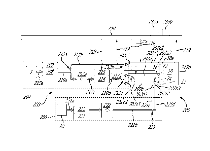
[0028] Referring now to Fig. 3, the fuel injection system 200 is shown in
greater detail. In
the embodiment shown, the system 200 supplies fuel to first and second
injectors 202a, 202b of
the engine 10; each of the first and second injectors 202a, 202b being in
fluid communication
with a respective one of the main combustion chamber 32 and the pilot
subchamber 72. A third
injector 202c is used herein and its function is described below. The system
200 includes an
actuation fluid system 203, which includes a circuit 204 hydraulically
connected to pump(s) and
pressure regulating valve(s), and an injection fluid circuit 206. Those
circuits are shown in
dashed lines in Fig. 3. The actuation circuit 204 is used to inject an
actuation fluid from a source
S of the actuation fluid to the injectors 202a, 202b, 202c. The actuation
fluid is used by the
injectors 202a, 202b to increase a pressure of the injection fluid received
therein. More detail
about these injectors are presented herein below with reference to Fig. 5.
Herein, the actuation
fluid is a lubricant, such as oil, and the source S of the actuation fluid is
a lubricant reservoir.
Other actuation fluids are contemplated. Such actuation fluids may be, for
instance, fuel,
hydraulic fluid, or any other suitable incompressible fluid. In the embodiment
shown, a third
injector 202c is used for injecting lubricant into a lubricant port 10a of the
engine 10. As shown
in Fig. 1, the third injector 202c is received within an aperture 18a of the
peripheral wall 18 and
is operable to inject lubricant to lubricate an inner surface of the
peripheral wall 18 that is in
sealing engagement with the rotor 24. Other configurations are contemplated.
[0029] Referring now to Fig. 5, there is shown an exemplary embodiment of
an injector 120.
In the embodiment shown in Figs. 3-4, all of the injectors 202a, 202b, 202c,
302a, 302b, 302c
are intensifier injectors as described below with reference to Fig. 5. The
injector 120 is an
intensifier injector and has two inlets, namely, an actuation inlet 120a and a
fuel inlet 120b. The
fuel inlet 120b is a lubricant inlet for the third injectors 202c, 302c, which
are used to inject
lubricant into the engine 10. Herein, an intensifier injector refers to an
injector able to create a
pressure ratio between an outlet and an inlet of said injector. In the
embodiment shown, the
pressure ratio is greater than one such that the fuel pressure at the outlet
is greater than that at
the inlet. Other pressure ratios are contemplated. Herein, the intensifier
injector is a pressure-
intensified hydraulically-actuated electronically-controlled injector.
7
Date Recue/Date Received 2021-05-14
[0030] The injector 120 has a body 122 and a nozzle 124 protruding axially
from the body
122 along an injector axis A. The actuation inlet 120a and the fuel inlet 120b
are defined in the
body 122. The nozzle 124 defines a fuel outlet 120c0f the injector 120 via
which the fuel exits
the injector 120 to be injected into a combustion chamber. The body 122
defines an internal
actuation chamber 122a that is hydraulically connectable to the actuation
circuit 204 via a first
internal passage 122b and a second internal passage 122c both defined in the
body 122. In the
embodiment shown, a spool valve 126 is slidingly received within a valve
chamber 122d defined
in the body 122 of the injector 120. The valve chamber 122d is located between
the first and
second internal passages 122b, 122c of the body 122 of the injector 120. The
injector 120 has
an open state in which the fuel is able to exit the injector 120 via the fuel
outlet 120c upon the
actuation fluid received within the injector 120 and a closed state in which
the fuel is limited from
exiting the injector 120.
[0031] The spool valve 126 translates relative to the body 122 and within
the valve chamber
122d along an axis transverse to the injector axis A. The spool valve 126
allows selective fluid
communication between the source S (Fig.3) of the actuation fluid and the
internal chamber
122a or between the internal chamber 122a and a vent passage 122e defined by
the body 122.
In other words, the spool valve 126 is movable between a first position in
which the source S of
the actuation fluid is hydraulically connected to the internal chamber 122a
and disconnected
from the vent passage 122e, and a second position in which the source S is
disconnected from
the internal chamber 122a and in which to the vent passage 122e is
hydraulically connected to
the internal chamber 122a for draining the actuation fluid out of the internal
chamber 122a. The
vent passage 122e is hydraulically connected to the source S for receiving the
actuation fluid
discarded by the injector 120. Further detail about the operation of the
injector 120 are
presented herein below.
[0032] In the embodiment shown, an electromagnet 128 is disposed around the
body 122 of
the injector 120 at an axial location relative to the injector axis A that
registers with the spool
valve 126. The electromagnet 128 is operatively connected to an engine control
unit (ECU) 230
(Fig. 3) of the engine 10. The ECU 230 is operable to send signals to the
electromagnet 128 to
magnetize said electromagnet 128 to bias the spool valve 126 in either one of
the first and
second positions described above. More details about the operation of the
injector 120 are
presented herein below.
8
Date Recue/Date Received 2021-05-14
[0033] In the embodiment shown, the moving of the valve 126 includes
electrifying the
electromagnet 128. The moving of the valve 126 includes, magnetically moving
the valve 126
from the first position to the second position. In the embodiment shown, the
ECU 230 receives
signal from a second electromagnet 129 disposed around the spool valve 126;
the signal
indicates to the ECU 230 if the spool valve 126 was effectively moved to the
desired one of the
first and second positions by the electromagnet 128. If the ECU 230 determines
that the spool
valve 126 was not moved to the desired one of the first and second positions
based on the
signal received from the second electromagnet 129, the ECU 230 moves the spool
valve 126 to
the desired one of the first and second positions by electrifying the second
electromagnet 129.
[0034] The injector 120 has a piston assembly 130 including a piston 130a
that is slidably
received within the internal chamber 122a. A diameter of the piston 130a
matches that of the
internal chamber 122a such that a sealing engagement is defined between
corresponding
peripheral walls of the internal chamber 122a and piston 130a. It will be
appreciated that a
sealing member, such as an 0-ring, may be located radially between the
peripheral walls of the
internal chamber 122a and the piston 130a. The piston assembly 130 is movable
back and forth
along the injector axis A. The piston 130a is secured to a shank 130b
protruding therefrom
along the injector axis A. The shank 130b of the piston 130 is slidingly
received within a third
internal passage 122f defined by the body 122 of the injector 120. A diameter
of the shank 130b
matches that of the third internal passage 122f such that a sealing engagement
is defined
between the peripheral walls of the third internal passage 122f and shank
130b. A sealing
member may be disposed therebetween.
[0035] The body 122 of the injector 120 further defines an injection fluid
inlet passage 122g
and an injection fluid outlet passage 122h. The injection fluid inlet passage
122g has an inlet
hydraulically connected to the source S and an outlet hydraulically connected
with the second
internal passage 122f. The injection fluid outlet passage 122h has an inlet
hydraulically
connected to the second internal passage 122f. The fuel inlet 120b of the
injector 120
corresponds to the inlet of the injection fluid inlet passage 122g. In the
embodiment shown, a
one-way valve is located in the passage 122g to limit the oil from flowing
back toward the oil
source via the internal passage 122g when the piston 130 is pushed down. The
oil inlet 120b of
the injector 120 corresponds to the inlet of the injection fluid inlet passage
122g.
[0036] The body 122 of the injector 120 further defines an injection
internal chamber 122i.
The injector 120 includes a needle assembly 132 axially movable relative to
the injector axis A.
9
Date Recue/Date Received 2021-05-14
The needle assembly 132 has a second piston 132a slidingly received within the
injection
internal chamber 122i and a needle 132b protrudes axially from the piston
132a. Diameters of
the second piston 132a and the injection internal chamber 122i matches such
that a sealing
engagement is defined therebetween. Again, a sealing member may be disposed
therebetween.
[0037] The needle 132b is partially received within the injection internal
chamber 122i and
partially received within a fourth internal passage 122j; the fourth internal
passage 122j
communicating with the injection internal chamber 122i and with an internal
passage 124a
defined by the nozzle 124. An outlet of the injection fluid outlet passage
122h is hydraulically
connected the fourth internal passage 122j of the injector 120.
[0038] The needle 132b is movable along the injector axis A and relative to
the body 122 of
the injector 120 between a first position in which the needle 132b defines a
sealing engagement
with the nozzle 124 thereby limiting fluid flow communication via outlets 124b
of the nozzle 124
and a second position in which the needle 132b is spaced apart from said
outlets 124b thereby
allowing the fuel to exit the internal passage 124a of the nozzle 124. In
other words, in the first
position, the needle 132b is in abutment against an inner wall of the nozzle
124 to block the
outlets 124b of the nozzle 124.
[0039] Operation of the injector 120 is now described. The actuation fluid
is received within
the injector 120 via the first internal passage 122b and allowed to fill the
internal chamber 122a
upon the spool valve 124 being in the first position. By filling the internal
chamber 122a,
pressure accumulates therein and pushes the piston 130a along the injector
axis A toward the
nozzle 124 in a downward direction Dl. A biasing member 138 located within the
internal
chamber 122a is thereby compressed. By moving axially along the injector axis
A, the fuel that
is received within the third internal passage 122f via the injection fluid
inlet passage 122g is
compressed by the shank 130b and pushed out of the third internal passage 122f
via the
injection fluid outlet passage 122h. The fuel then reaches the injection
internal chamber 122i via
the fourth internal passage 122j. A pressure build-up is created within the
injection internal
chamber 122i that pushes the second piston 132a away from the nozzle 124 in an
upward
direction D2 and along the injector axis A thereby compressing a second
biasing member 140
and creating a gap between the needle 132b and the inner wall of the nozzle
124 thereby
uncovering the outlets 124b of the nozzle 124 and allowing the fuel received
within the injection
internal chamber 122i to exit said chamber 122i via the internal passage 124a
of the nozzle 124.
The first and second biasing members 138, 140 are calibrated in function of
the desired
Date Recue/Date Received 2021-05-14
pressure of the fuel at the fuel outlet 120c. In the embodiment shown, the
biasing members 138,
140 are used to bring the first and second pistons to their initial position
when pressures re-
equilibrate when the spool valve is brought back into the second position and
injection is no
longer required. The biasing members 138, 140 are calibrated to maintain a
proper dynamic of
the system.
[0040] When injection of the fuel is no longer required, the electromagnet
128 is energized
to move the spool valve 126 from the first position to the second position in
which fluid flow
communication between the source S and the internal chamber 122a is limited.
By being in the
second position, the spool valve 126 allows the internal chamber 122a to
communicate with the
vent passage 122e and allows the actuation fluid to exit the internal chamber
122a. More
specifically, in the second position of the spool valve 126, there is no more
actuation fluid
received in the internal chamber 122a from the source S and a fluid path is
created between the
internal chamber 122a and the vent passage 122e. Therefore, the first biasing
member 138 is
able to push on the piston 130a to decrease an effective volume of the
internal chamber 122a
thereby pushing the actuation fluid contained therein out of the injector 120
via the vent passage
122e. The injected actuation fluid may then be flown back to the source S.
Other configurations
are contemplated. In a particular embodiment, the actuation fluid exiting the
injector 120 via the
vent passage 122e may be flown to other components.
[0041] As shown in Fig. 5, a cross-sectional area of the piston 130a taken
along a plane
normal to the injector axis A is greater than that of the shank 130b.
Therefore, this difference in
surface area allows the injector 120 to impart an increase in pressure between
that received in
the internal chamber 122a and that at the fuel outlet 120c of the injector
120. This pressure
increase varies in function of a ratio of the piston cross-sectional area to
the shank cross-
sectional area; the greater this ratio, the greater the pressure increase.
[0042] The injector 120 is able to control a quantity of fuel injected by
varying a time
duration in which the spool valve 126 remains in the first position. This time
duration is
calculated by the ECU 230 in function of operating parameters of the engine
12. These
parameters include, for instance, the actuation fluid temperature, the
actuation fluid pressure,
the speed of engine 12, a temperature of a liquid coolant of the engine 10 and
so on. Sensors
may be used to measure those parameters.
[0043] Referring back to Fig. 3, each of the injectors 202a, 202b, 202c
operates as describe
above with reference to Fig. 5 and are characterized by a respective pressure
ratio. In the
11
Date Recue/Date Received 2021-05-14
embodiment shown, the first injector 202a has a pressure ratio of 5 to 1. The
second injector
202b has a pressure ratio of 10 to 1. In the embodiment shown, the first
injector 202a is
operatively connected to the pilot subchamber 72 (Fig. 1) of the rotary engine
10. In the
embodiment shown, the third injector has a pressure ratio of 1 to 1. In the
embodiment shown,
the third injector 202c is used to inject oil in a location in need of
lubrication. The third injector
202c may be used to supply the oil to carry other function, for instance, to
power an actuator of
the engine 10. The pressure ratio is the ratio of a pressure of the injection
fluid (e.g., fuel) at the
fuel outlet 120c (Fig. 5) of the injector to that at the fuel inlet 120b (Fig.
5) thereof. The pressure
ratios of the injectors may range from 1 to 10. Other values are contemplated.
[0044] The actuation system and circuit 203, 204 of the fuel injection
system 200 are
described herein below following a direction of the actuation fluid flowing
therein from the source
S of the actuation fluid to the injectors 202a, 202b, 202c. Then, the
injection circuit 206 of the
fuel injection system 200 is described following a direction of the fuel from
the fuel source 30 to
the injectors 202a, 202b.
[0045] The actuation fluid is drawn from the source S by a low-pressure
pump 208 of the
system 203 hydraulically connected to the source S of the actuation fluid. In
the embodiment
shown, the actuation fluid pressure at an outlet of the low-pressure pump 208
is from about 200
to about 500 PSI. The low-pressure pump 208 is operatively connected to a
pressure regulating
valve 209 to maintain a pressure exiting the low-pressure pump 208
substantially constant. The
actuation fluid flows via a first conduit 210a to a first splitter 212a where
it is divided in a first
portion flowing toward the first and second injectors 202a, 202b and a second
portion flow
towards the third injector 202c. The first splitter 212a has two outlets, one
of the two outlets of
the first splitter 212a is hydraulically connected to the first and second
injectors 202a, 202b and
the other of the two outlets of the first splitter 212a is hydraulically
connected to the third injector
202c. The first splitter 212a is hydraulically connected to second and third
conduits 210b, 210c.
The second conduit 210b is hydraulically connected to the third injector 202c
and the third
conduit 210c is hydraulically connected to the first and second injectors
202a, 202b.
[0046] From the first splitter 212a, the actuation fluid flows via the
second conduit 210b to
both of the actuation inlet 202c1 and the injection inlet 202c2 of the third
injector 202c. In the
embodiment shown, the actuation fluid flowing toward the inlets 202c1, 202c2
of the third
injector 202c is divided in two by a second splitter 212b. The second splitter
212b has two
outlets; one of the two outlets of the second splitter 212b is hydraulically
connected to the
12
Date Recue/Date Received 2021-05-14
actuation inlet 202c1 of the third injector 202c and the other of the two
outlets of the second
splitter 212b is hydraulically connected to the injection inlet 202c2 of the
third injector 202c. A
first portion flows to the actuation inlet 202c1 of the third injector 202c
and a second portion
flows to the injection inlet 202c2 of the third injector 202c. The actuation
fluid injected in the
actuation inlet 202c1 of the third injector 202c contributes in pushing the
actuation fluid, which is
lubricant herein, injected into the injection inlet 202c2 of the third
injector 202c as described
herein above with reference to Fig. 5. Then, the lubricant is injected into
the area in need of
lubrication via the lubrication port 10a of the engine 10.
[0047] Going back to the first splitter 212a, a remainder of the flow
flowing via the first
conduit 210a is directed toward the first and second injectors 202a, 202b via
the third conduit
210c. A first fuel filter 211a is hydraulically connected to the third conduit
210c downstream of
the first splitter 212a. The third conduit 210c is hydraulically connected to
a high-pressure pump
214 that draws the actuation fluid from the source S of the actuation fluid
and increases its
pressure. The high-pressure pump 214 is hydraulically connected downstream of
the first filter
211a and downstream of the first splitter 212a. It will be appreciated that
the first filter 211a may
be located upstream of the splitter 212a. A pressure control valve 215 is
operatively connected
to the high pressure pump 214 and is used to control a pressure of the
actuation fluid at an
outlet of the high pressure pump 214. In the embodiment shown, a pressure of
the actuation
fluid exiting the high-pressure pump is from about 2000 PSI to about 3000 PSI.
[0048] From the high-pressure pump 214, the actuation fluid is directed to
the first and
second injectors 202a, 202b via a high-pressure conduit 210d and via a third
splitter 212c. The
third splitter 212c divides the flow of the actuation fluid received from the
high-pressure pump
214 between the first and second injectors 202a, 202b. The third splitter 212c
has two outlets,
one of the two outlets of the third splitter 212c is hydraulically connected
to the actuation inlet
202a1 of the first injector 202a and the other of the two outlets of the third
splitter 212c is
hydraulically connected to the actuation inlet 202b1 of the second injector
202b. In the
embodiment shown, both of the first and second injectors 202a, 202b receive
the actuation fluid
at the same pressure. But, as described herein above, the first and second
injectors 202a, 202b
are characterized by different pressure ratios (e.g., 5 to 1 vs 10 to 1) and,
as such, inject fuel
received at their injection inlets 202a2, 202b2 into the pilot subchamber 72
and main
combustion chamber 32 of the engine 10 at two different pressures via their
respective injection
outlets 202a3, 202b3. Herein, the fuel pressure injected in to the pilot
subchamber 72 is less
than that injected in to the main combustion chamber 32.
13
Date Recue/Date Received 2021-05-14
[0049] The injection circuit 206 is now described. The injection circuit
206 includes a low
pressure fuel pump 220 that is operable to draw fuel from the fuel source 30
via a fuel conduit
221a and to inject the fuel to a fuel filter 222. The low-pressure fuel pump
220 is operatively
connected to a pressure regulating valve 221 to maintain a pressure exiting
the low-pressure
fuel pump 220 substantially constant. From the fuel filter 222, the fuel is
directed toward the first
and second injectors 202a, 202b via a fuel conduit 221b. A fuel splitter 223
is hydraulically
connected to the fuel conduit 221b and divides the flow of fuel in two. Two
fuel conduits 221c,
221d stems from the fuel splitter 223 and are each hydraulically connected to
a respective one
of the injection inlets 202a2, 202b2 of the first and second injectors 202a,
202b. In other words,
the fuel splitter 223 has two outlets; one of the two outlets of the fuel
splitter 223 is hydraulically
connected to the injection inlet 202a2 of the first injector 202a and the
other of the two outlets of
the fuel splitter 223 is hydraulically connected to the injection inlet 202b2
of the second injector
202b. It will be appreciated that other configurations of the fuel circuit are
contemplated. For
instance, each of the first and second injector 202a, 202b may be
hydraulically connected to a
respective one of two different fuel sources (e.g., two fuel tanks). In the
embodiment shown, the
pressures of the fuel at the injection inlets 202a2, 202b2 of the first and
second injectors 202a,
202b are the same.
[0050] In the embodiment shown, the engine control unit (ECU) 230 is
operatively
connected to the engine 10 and the fuel injection system 200. The ECU 230 is
operatively
connected to the pressure control valve 215, to a pressure sensor 217a, which
is operatively
connected to the high-pressure conduit 210d between the high pressure pump 214
and the third
splitter 212c, to each of the first, second, and third injectors 202a, 202b,
202c, and to a speed
sensor 217b, which is operatively connected to the engine 10 to measure a
rotation speed of a
shaft of the engine 10. Suitable communication links 219, which may be wired
or wireless, are
used to connect the ECU 230 to the above mentioned components. The ECU 230
receives data
from the pressure sensor 217a and the speed sensor 217b and generates
operational
parameters and sends signals to the pressure control valve 215 and to the
injectors 202a, 202b,
202c to control injection of the fuel into the combustion chamber 72, 32 of
the engine 10. These
signals are used to control, for instance, the pressure of the actuation
fluid, the pressure of the
fuel injected into the engine 10, the duration of injection, the quantity of
fuel injected. The ECU
230 is operatively connected to the electromagnets 128 (Fig. 5) of each of the
injectors 202a,
202b, 202c for controlling whether each of said injectors are in their open or
closed states.
14
Date Recue/Date Received 2021-05-14
[0051] The ECU 230 is able to control a duration of the injection, the
actuation fluid
pressure, a voltage of the ignition element 84 (Fig. 1), which is a glow plug
in the embodiment
shown, timing of the injection, and so on. The ECU is able to control voltage
and current using a
specific profile to open up the injector needle at a specific time compared to
crank angle (e.g.,
angular position of the rotor within the outer body.). In a particular
embodiment, the ECU 230
controls the first and second injectors 202a, 202b such that the fuel is
injected respectively into
the main and pilot subchamber simultaneously. In some cases, a small delay
between the fuel
injection of the first and second injectors is possible. In a particular
embodiment, a maximum
delay between an injection of fuel into the pilot subchamber and an injection
of fuel into the main
chamber is at most 0.002 second. In the embodiment shown, the first and second
injectors
202a, 202b inject fuel respectively into the pilot and main combustion
chambers 72, 32 while the
pilot subchamber 72 is in fluid flow communication with the main chamber 32.
[0052] In the embodiment shown, the fuel is injected at the same pressures
to the injection
inlets 202a2, 202b2 of the first and second injectors 202a, 202b and the
actuation fluid is
injected into the actuation inlets 202a1, 202b1 at the same pressures. Since
each of the first
and second fuel injectors 202a, 202b has its own pressure ratio (e.g., 5 to 1
and 10 to 1), the
pressure of the fuel injected in the combustion chambers via the injection
outlets 202a3, 202b3
of the first and second injectors 202a, 202b are different.
[0053] Still referring to Fig. 3, the ECU 230 includes a processing unit
230a and a computer-
readable medium 230b operatively connected to the processing unit 230a and
have instructions
stored thereon executable by the processing unit 230a for receiving data from
the sensors 217a,
217b; determining a main injection profile and a pilot injection profile of
the main and pilot fuel
injectors in function of the received data; and injecting the fuel in the at
least one combustion
chamber per the determined injection profile. In the present embodiment, the
determining of the
main injection profile and the pilot injection profile includes determining
main and pilot
frequencies of injection of the fuel and/or main and pilot amounts of fuel to
be injected. In the
embodiment shown, receiving the data from the sensors 217a, 217b includes
receiving data
about a rotational speed of a shaft of the aircraft engine from the speed
sensor 217b and/or
about a pressure of the main and pilot actuation fluids from the pressure
sensor 217a of the
sensors. Herein, the injecting of the fuel further includes controlling the
outlet pressure of the
high-pressure pump 214 with the pressure control valve 215 operatively
connected to the ECU
230 and to the high-pressure pump 214.
Date Recue/Date Received 2021-05-14
[0054] Referring now to Fig. 4, another embodiment of a fuel system is
shown generally at
300. For the sake of conciseness, only elements that differ from the fuel
system 200 described
herein above with reference to Fig. 3 are described herein below. The fuel
system 300 includes
an actuation system 303 including an actuation circuit 304, which is shown in
dashed line, and
the fuel circuit 206, which corresponds to the fuel circuit 206 of the system
200 described above
with reference to Fig. 3. In the embodiment shown, the first, second, and
third injectors 302a,
302b, 302c have the same pressure ratio, which may be, for instance, 1, 5, or
10. Other values
are contemplated.
[0055] The actuation fluid, which may be a lubricant such as oil, is drawn
from the source S
by a low-pressure pump 308 and flows within a first conduit 310a. The low-
pressure pump 308
is operatively connected to a pressure regulating valve 309 to maintain a
pressure exiting the
low-pressure pump 308 substantially constant. The low-pressure pump 308 is
hydraulically
connected to a first splitter 312a via a second conduit 310b where it is
divided in a first portion
flowing toward the third injector 302c and a second portion flows towards the
first and second
injectors 302a, 302b.
[0056] From the first splitter 312a, the actuation fluid flows to both of
the actuation inlet
302c1 and the injection inlet 302c2 of the third injector 302c via a third
conduit 310c. In the
embodiment shown, the actuation fluid flowing toward the inlets 302c1, 302c2
of the third
injector 302c is divided in two by a second splitter 312b. A first portion
flows to the actuation
inlet 302c1 of the third injector 302c via a fourth conduit 310d and a second
portion flows to the
injection inlet 302c2 of the third injector 302c via a fifth conduit 310e.
Similarly to the
embodiment described above with reference to Fig. 3, the third injector 302c
is used to inject
lubricant to the lubrication port 10a of the engine 10.
[0057] Going back to the first splitter 312a, the second portion of the
flow exiting the low-
pressure pump 308 flows toward the first and second injectors 302a, 302b via a
sixth conduit
310f. The first splitter 312a is hydraulically connected to a high-pressure
pump 314 via the sixth
conduit 310f. The high-pressure pump 314 draws the actuation fluid from the
source C and
increases its pressure. In the embodiment shown, the pressure of the actuation
fluid at an outlet
of the high-pressure pump 314 is from 2000 PSI to 5000 PSI. The outlet of the
high-pressure
pump 314 is hydraulically connected to a first pressure regulating valve 324a
via a seventh
conduit 310g. The first pressure regulating valve 324a has a main outlet 324a1
hydraulically
16
Date Recue/Date Received 2021-05-14
connected to a third splitter 312c and a return outlet 324a2 hydraulically
connected to the sixth
conduit 310f downstream of the first splitter 312a and upstream of the high-
pressure pump 314.
[0058] The third splitter 312c has a first outlet hydraulically connected
to the actuation inlet
302b1 of the second injector 302b and a second outlet hydraulically connected
to a second
pressure regulating valve 324b. The second pressure regulating valve 324h has
a main outlet
324b1 hydraulically connected to the injection inlet 302a1 of the first
injector 302a and a return
outlet 324b2 hydraulically connected to the sixth conduit 310f downstream of
the first splitter
312a and upstream of the high-pressure pump 314.
[0059] The first and second pressure regulating valves 324a, 324h are
devices used to
maintain substantially constant a pressure at their respective main outlets
324a1, 324b1
regardless of the pressure of the fluid they receive. Each of these devices
may include, for
instance, a piston being biased in sealing engagement with an opening, which
lead to its
respective return outlets 324a2, 324b2, via a spring and operable to allow
fluid communication
via the return outlets 324a2, 324b2 when the fluid pressure is high enough to
overcome a
biasing force of the spring. Any suitable pressure regulating valve may be
used. A pressure
control valve differs than a pressure regulating valve since the pressure
control valve is
operatively connected to the ECU 230 and is able to change a value of the
outlet pressure. A
pressure regulating valve is fully mechanical and a control valve is in closed
loop with the ECU
230. The pressure regulating valves 324a, 324h are mechanical device and are
not connected
to the ECU 230. In the embodiment shown, an outlet valve pressure of the first
pressure
regulating valve 324a is different than that of the second pressure regulating
valve 324b such
that the pressure injected at the actuation inlet 302b1 of the second injector
302b is different
than that injected at the actuation inlet 302a1 of the first injector 302a. In
the embodiment
shown, the pressure at the main outlet 324b1 of the second pressure regulating
valve 3324b is
less than that at the main outlet 324a1 of the first pressure regulating valve
324a.
[0060] In the embodiment shown, the actuation fluid exits the high-pressure
pump 314 and
flows into the first pressure regulating valve 324a. The first pressure
regulating valve 324a is
used to regulate the pressure of the actuation fluid exiting the high-pressure
pump 314. A
portion of the flow exiting the first pressure regulating valve 324a is flown
to the second
regulating valve 324h to decrease its pressure before injecting the actuation
fluid into the first
injector 302a. The two pressure regulating valves 324a, 324b are used to vary
the pressure of
17
Date Recue/Date Received 2021-05-14
the actuation fluid received at the actuation inlets 302a1, 302b1 of the first
and second injectors
302a, 302b such that the pressures at the fuel outlets 302a3, 302b3 are
different.
[0061] The fuel system 300 includes the fuel circuit 206 that is operable
to inject the fuel at
the injection inlets 302a2, 302b2 of the first and second injectors 302a, 302b
as described
herein above with reference to Fig. 3. In the embodiment shown, the fuel is
injected at the same
pressure to both of the first and second injectors 302a, 302b.
[0062] Referring to all Figures, for injecting the fuel into the rotary
internal combustion
engine, fuel is injected into the at least one combustion chamber at a main
pressure via a main
injector by injecting a main actuation fluid into the main injector; and the
fuel is injected into the
pilot subchamber, while the pilot subchamber is in fluid flow communication
with the at least one
combustion chamber, at a pilot pressure different than the main pressure via a
pilot injector by
injecting a pilot actuation fluid into the pilot injector.
[0063] In the embodiment shown, injecting the fuel into the at least one
combustion
chamber and injecting the fuel into the pilot subchamber include increasing a
fuel pressure
within the main injector at a value being greater than a fuel pressure exiting
the pilot injector;
and/or injecting the main actuation fluid at a main actuation pressure being
different than a pilot
actuation pressure of the pilot actuation fluid injected into the pilot
injector.
[0064] The disclosed fluid injection systems 200, 300 may exhibit the
flexibility of injecting a
fluid able to burn within an internal combustion chamber equipped with
multiple injectors within
the same combustion chamber at different pressures simultaneously. This may be
done without
adding complexity to the system. This may allow more flexibility on the
injection strategy and
may allow to design and optimize the geometry of the pre-chambers (e.g. pilot
subchamber) and
main chambers in order to improve the overall thermal efficiency and
combustion stability.
Furthermore, this may give the capability to change the penetration rate of
the fluid per injector,
control the droplet diameter of the fuel, have a better control of the
ignition delay and emissions,
optimize the injection duration per injector in close loop with key
performance parameters. This
concept may be applicable for all engine applications design to burn a fluid.
The systems 200,
300 concepts use three injectors and two fluids, which are herein fuel and
oil, but the amount of
injectors and fluids may be changed. For instance, each of the injectors may
be hydraulically
connected to a respective one of more than one sources of actuation fluids;
and/or hydraulically
18
Date Recue/Date Received 2021-05-14
connected to a respective one of fuel sources. In other words, each injector
may be driven by a
dedicated actuation fluid to inject a specific fluid (e.g., fuel, lubricant,
etc).
[0065] In a particular embodiment, the conduits of the disclosed systems
200, 300 are
exposed to lower pressures than conduits of common rail systems. In a
particular embodiment,
the conduits of the disclosed systems are exposed to fluid pressures that are
about 10 times
lower than those of a common-rail system (e.g., 3000 PSI vs 30000 PSI). The
disclosed fuel
injection systems include only one high-pressure system. For the same level of
complexity, the
system may give more flexibility since there may be no extra parts or
controllers. The disclosed
fuel injection systems 200, 300 may offer better control on penetration rate,
droplet diameter,
ignition delay, emissions and injection duration. They may offer more
flexibility to design and
optimize the combustion chambers and may improve cold start and transient
manoeuvers within
design space. The fuel injection system 300 described above with reference to
Fig. 4 allows to
identical injectors having the same pressure amplification ratio. This may be
advantageous
since the part counts of the engine may be lower than that of the system 200
described above
with reference to Fig. 3.
[0066] Embodiments disclosed herein include:
[0067] A. A fuel injection system for an aircraft engine having at least
one combustion
chamber of varying volume, comprising: a first fuel injector having a first
actuation inlet, a first
fuel inlet hydraulically connected to a fuel source, and a first fuel outlet
hydraulically connected
to the at least one combustion chamber, the first fuel injector defining a
first pressure ratio
defined as a first outlet pressure at the first fuel outlet to a first inlet
pressure at the first fuel
inlet; a second fuel injector having a second actuation inlet, a second fuel
inlet hydraulically
connected to the fuel source, and a second fuel outlet hydraulically connected
to the at least
one combustion chamber, the second fuel injector defining a second pressure
ratio defined as a
second outlet pressure at the second fuel outlet to a second inlet pressure at
the second fuel
inlet; and an actuation fluid system having a circuit hydraulically connected
to the first actuation
inlet and to the second actuation inlet, the first outlet pressure different
than the second outlet
pressure by having one or both of the first pressure ratio different than the
second pressure ratio
and a first actuation pressure from the actuation fluid system different than
a second actuation
pressure from the actuation fluid system.
19
Date Recue/Date Received 2021-05-14
[0068] B. A rotary internal combustion engine, comprising an outer body
defining a rotor
cavity; a rotor rotatable within the rotor cavity and in sealing engagement
with walls of the outer
body and defining at least one chamber of variable volume in the rotor cavity;
the outer body
defining a pilot subchamber communicating with the rotor cavity; a main fuel
injector having a tip
in communication with the rotor cavity at a location spaced apart from the
pilot subchamber, the
main fuel injector having a main actuation inlet hydraulically connected to a
source of an
actuation fluid, a main fuel inlet hydraulically connected to a fuel source,
and a main fuel outlet
hydraulically connected to the at least one combustion chamber, the main fuel
injector defines a
main pressure ratio defined as a main outlet pressure at the main fuel outlet
to a main inlet
pressure at the main fuel inlet; and a pilot fuel injector having a tip in
communication with the
pilot subchamber, the pilot fuel injector having a pilot actuation inlet
hydraulically connected to
the source of the actuation fluid, a pilot fuel inlet hydraulically connected
to the fuel source, and
a pilot fuel outlet hydraulically connected to the at least one combustion
chamber via the pilot
subchamber, the pilot fuel injector defines a pilot pressure ratio defined as
a pilot outlet pressure
at the pilot fuel outlet to a pilot inlet pressure at the pilot fuel inlet, an
actuation fluid system
having a circuit hydraulically connected to the main actuation inlet and to
the pilot actuation
inlet, the actuation fluid system operable to inject the actuation fluid at a
main actuation
pressure to the main actuation inlet and to inject the actuation fluid at a
pilot actuation pressure
to the pilot actuation inlet, the main outlet pressure different than the
pilot outlet pressure by
having one or both of the main pressure ratio different than the pilot
pressure ratio and the main
actuation pressure different than the pilot actuation pressure.
[0069] Embodiments A and B may include any of the following elements, in
any
combinations:
[0070] Element 1: a high-pressure pump hydraulically connected to both of
the first
actuation inlet and the second actuation inlet, the first pressure ratio
different than the second
pressure ratio. Element 2: the first actuation pressure is equal to the second
actuation pressure.
Element 3: the first pressure ratio is 5 and the second pressure ratio is 10.
Element 4: a high-
pressure pump hydraulically connected to both of the first actuation inlet and
the second
actuation inlet, the first actuation inlet hydraulically connected to the high-
pressure pump via a
first pressure regulating valve and the second actuation inlet hydraulically
connected to the
high-pressure pump via a second pressure regulating valve, an outlet valve
pressure of the first
pressure regulating valve different than that of the second pressure
regulating valve. Element 5:
the first actuation inlet is hydraulically connected to the high-pressure pump
via both of the first
Date Recue/Date Received 2021-05-14
pressure regulating valve and the second pressure regulating valve. Element 6:
the first
pressure ratio is equal to the second pressure ratio. Element 7: the first
pressure ratio ranges
from 1 to 10. Element 8: each injector of the first injector and the second
injector has a body, a
nozzle defining a fuel outlet of the injector and protruding from the body,
and a needle slidingly
received within the nozzle, the needle movable from an engaged position in
which the needle is
sealingly engaged to the nozzle and a disengaged position in which the needle
allows fuel to
exit the injector. Element 9: the body of the injector defines an actuation
chamber hydraulically
connected to the circuit and an injection chamber hydraulically connected to
the fuel source, a
first piston slidingly received within the actuation chamber, a second piston
slidingly received
within the injection chamber and connected to the needle, movement of the
first piston upon
reception of the first or second actuation fluid within the actuation chamber
pushing the fuel
received via the first or second fuel inlet into the injection chamber thereby
pushing on the
second piston to move the needle from the engaged position toward the
disengaged position.
Element 10: the first actuation fluid and the second actuation fluid are
lubricant from a source of
the lubricant. Element 11: a high-pressure pump hydraulically connected to
both of the main
actuation inlet and the pilot actuation inlet, the main pressure ratio
different than the pilot
pressure ratio. Element 12: the main actuation pressure is equal to the pilot
actuation pressure.
Element 13: an engine control unit (ECU) operatively connected to the main
fuel injector and the
pilot fuel injector, the ECU having a processing unit and a computer readable
medium
operatively connected to the processing unit and containing instructions
executable by the
processing unit for: receiving data from sensors of the fuel injection system;
determining a main
injection profile and a pilot injection profile of the main and pilot fuel
injectors in function of the
received data; and injecting the fuel in the at least one combustion chamber
per the determined
injection profile. Element 14: the determining the main injection profile and
the pilot injection
profile includes determining main and pilot frequencies of injection of the
fuel and/or main and
pilot amounts of fuel to be injected. Element 15: the receiving of the data
from the sensors
includes receiving data about a rotational speed of a shaft of the aircraft
engine from a speed
sensor and/or about a pressure of the main and pilot actuation fluids from a
pressure sensor of
the sensors. Element 16: a high-pressure pump is hydraulically connected to
both of the main
actuation inlet and the pilot actuation inlet, the injecting of the fuel
further comprising controlling
an outlet pressure of the high-pressure pump with a pressure control valve
operatively
connected to the ECU and to the high-pressure pump.
21
Date Recue/Date Received 2021-05-14
[0071]
The embodiments described in this document provide non-limiting examples of
possible implementations of the present technology. Upon review of the present
disclosure, a
person of ordinary skill in the art will recognize that changes may be made to
the embodiments
described herein without departing from the scope of the present technology.
Yet further
modifications could be implemented by a person of ordinary skill in the art in
view of the present
disclosure, which modifications would be within the scope of the present
technology.
22
Date Recue/Date Received 2021-05-14