Note: Descriptions are shown in the official language in which they were submitted.
CA 03137392 2021-10-19
WO 2020/251439 PCT/SE2020/000003
Saw tooth setting arrangement
The present invention relates to saw tooth setting arrangement according to
the introductory
portion of the independent claim.
In particular, it relates to such a saw tooth setting arrangement intended to
set teeth on a saw
band.
Background of the invention
Setting teeth means that saw teeth are alternately bent from the saw band in
one direction and
alternately bent in the opposite direction. The setting must be done with high
degree of precision,
both insofar as that each saw tooth bent in one direction are bent to the same
amount, and in that
saw teeth bent in the opposite directions are bent to the same amount. To
achieve a completely
symmetrical setting of teeth in both directions, setting of teeth with high
precision is required,
which is expensive.
An object of the invention is therefore to provide a saw tooth setting
arrangement which can
provide symmetrical setting of teeth in both directions, with a simpler design
of the saw tooth
setting arrangement than is possible with prior art saw tooth setting
arrangements.
These and other objects are attained by a saw tooth setting arrangement
according to the
characterising portion of the independent claim.
Summary of the invention
The invention relates to a arrangement for setting saw teeth on a saw band 4,
the arrangement
comprising a base 1 through which the saw band can slide. The base is provided
with a receiving
device 6 for receiving a saw tooth setting device 8. The saw tooth setting
device 8 is arranged to
be able to set saw teeth in one direction. The receiving device 6 is designed
so that it can receive
the saw tooth setting device 8 on both sides of the saw band, so that the saw
tooth setting device
8 received on one side of the saw band can set saw teeth in a first direction
and so that the saw
tooth setting device 8 received on the opposite side of the saw band can set
saw teeth in a
direction opposite to the first. Advantageously, This means that, even though
only a simple saw
1
CA 03137392 2021-10-19
WO 2020/251439 PCT/SE2020/000003
tooth setting device 8 arranged to be able to set saw teeth in one direction
is used, the
arrangement for setting saw teeth can set them in both directions.
In an advantageous embodiment, the arrangement comprises a band feeder 2-3
which can
incrementally feed the saw band 4 forward a selected number of tooth spacings.
In yet another advantageous embodiment, the receiving device 6 comprises a
first rod element
which projects outwards on both sides of the base at right angles to the side
of the saw band 4
and wherein the saw tooth setting device 8 comprises two through openings
which can receive
the first rod element.
The invention further relates to such a device in which the receiving device 6
comprises a second
rod element projecting outwards on both sides of the base at right angles to
the side of the saw
band 4 and where the saw tooth setting device 8 can rest against the second
rod element.
Brief description of the drawings
Fig. 1 shows a side view of an embodiment of an arrangement for setting saw
band teeth with a
feeder in a first position.
Fig. 2 shows a side view of the embodiment of the arrangement for setting saw
band teeth with
the feeder in a second position.
Fig. 3 shows a side view of the embodiment of the arrangement for setting saw
band teeth with
the feeder in a third position.
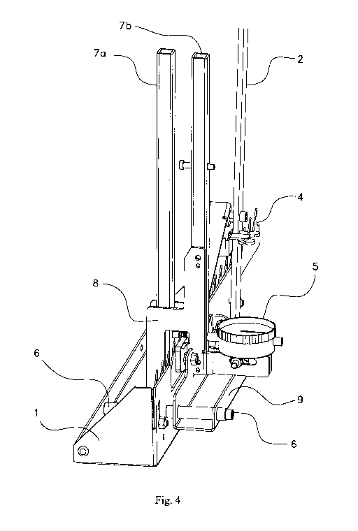
Fig. 4 shows at an angle from the front of the embodiment of the arrangement
for setting saw
band teeth with a saw tooth setting device oriented for setting in a first
direction.
Fig. 5 shows at an angle from the front of the embodiment of the arrangement
for setting saw
band teeth with the saw tooth setting device oriented for setting in a second
direction.
Fig. 6 shows at an angle from the front of the embodiment of the arrangement
for setting saw
band teeth with the saw tooth setting device removed.
2
CA 03137392 2021-10-19
WO 2020/251439 PCT/SE2020/000003
Description of a preferred embodiment
The invention relates to an arrangement for setting saw teeth on a saw band.
The arrangement
comprises a base over which the saw band is progressively fed to set saw tooth
after saw tooth.
The step-by-step process is illustrated in Figures 1-3. Setting means that the
saw teeth are
alternately bent away from the saw band towards one side and alternately bent
towards the
opposite side. The setting can be done in different ways, where a common way
is that every other
saw tooth is set in one direction, every other saw tooth is set in the
opposite direction. The setting
must be done with high degree of precision, both insofar as that each saw
tooth bent in one
direction are bent to the same amount, and in that saw teeth bent in the
opposite directions are
bent to the same amount.
The setting can also be more complex than setting every other to tooth the
right while setting
every other to tooth to the left, but for such more complex setting methods
there are
corresponding requirements for precision.
The saw-tooth setting arrangement is provided with a setting device which sets
one saw tooth at
a time with a high degree of precision. The setting device is reversible on
the base, so that the
saw teeth of the saw band can be set with high degree of precision in both
directions, without
having to lift the saw band out of the device, turn the saw band and reset the
saw band. Instead,
the setting device is lifted out of the base, turned and reset on the base.
Subsequently, setting of
saw teeth in a direction opposite to the first can be carried out. Figures 4-6
show the base with
the setting device mounted facing in one direction, the base with the setting
device mounted
facing in the opposite direction and the base with the setting device removed
to more clearly
illustrate the receiving device on the base which allows the setting device to
be received there in
two differently directed ways.
Fig. 1 shows an embodiment of a saw tooth setting arrangement for saw bands
with a feeder 2 in
a first position. The arrangement is here illustrated seen from the side, so
that the saw band runs
from left to right in the paper plane. The arrangement comprises a base 1 over
which the saw
band 4 runs in a groove and on which the other components are mounted. The
arrangement
comprises a saw tooth setting device 8 with a measuring dial 5 and these are
more clearly
illustrated in conjunction with figs 4-5. The device comprises a forward
feeder 2 in the form of
an arm rotatably arranged around an axis. A pusher 3 extends from the feeder,
from above the
3
CA 03137392 2021-10-19
WO 2020/251439 PCT/SE2020/000003
saw band and down to the top of the saw band. The pusher is rotatably
connected to the feeder 2
about an axis at a point above the saw band.
If the feeder is angled in the direction in which the saw band is to be
pushed, the pusher moves
down towards the saw band until it reaches a point between two saw teeth. If
the feeder is angled
further in the same direction, the pusher slides forward until it reaches a
saw tooth. In the figure,
the pusher has reached this position, where it abuts the bottom of a saw
tooth.
Fig. 2 shows the embodiment of the arrangement for setting saw band teeth with
the feeder in a
second position. Here, the feeder has been angled further in the same
direction, so the pusher has
here pushed the saw band forward a distance by pressing against the bottom of
the saw tooth.
Fig. 3 shows the embodiment of the arrangement for setting saw band teeth with
the feeder in a
third position. Here, the feeder has been angled maximally in the same
direction, so the pusher
has here pushed the saw band forward a well defined distance. The feeder acts
against an
adjustable stop element which controls the feeding so that if the feeder is
angled maximally from
end position to end position, the saw band is fed a given total number of saw
tooth spacings
forward. For a tooth setting method where every second saw tooth is set to the
right and every
other to the left, the stop element is set so that the saw band is fed two
full saw tooth spacings.
Thus, after one full forward shift, the next saw tooth for setting is in
position for setting.
Fig. 4 shows the embodiment of the arrangement for setting saw band teeth with
a setting device
mounted for setting in a first direction. The device is illustrated here
viewed at an angle from the
front, so that the saw band 4 runs towards the viewer out of the paper plane
but slightly angled to
the left. The saw band 4 runs in a groove in the base 1 and through the base a
first fastening rod 6
extends perpendicularly to the sides of the saw band.
The saw tooth setting device 8 comprises an arm pair 7a-b, which can be
manually clamped
together to effect the setting. The saw tooth setting device 8 with a
measuring dial 5 extends
from a lower fastening member 9 through which a first through opening extends.
The through
opening in the fastening member 9 is here threaded over the first fastening
rod 6 on one side of
the base and the fastening member 9 rests at its other end on a second
fastening rod, hidden by
the fastening rod 9.
4
CA 03137392 2021-10-19
WO 2020/251439 PCT/SE2020/000003
Fig. 5 shows the embodiment of the arrangement for setting saw band teeth with
the setting unit
mounted for setting in a second direction, opposite to the first. The
arrangement is here
illustrated viewed at an angle from the front, so that the saw band runs
towards the viewer out of
the paper plane but slightly angled to the left. A second through opening
extends in the lower
fastening member 9 of the saw tooth setting device 8. The second through
opening in the
fastening member 9 is here threaded over the first fastening rod 6 on one side
of the base and the
fastening member 9 rests at its other end on the second fastening rod, hidden
by the fastening
member 9.
By pushing the first fixing rod 6 into the second through opening in the lower
fastening member
9 of the saw tooth setting device 8, the saw tooth setting device 8 is
prevented from turning out
of position when the arm pair 7a-b is manually clamped together. By resting
the fastening
member 9 at its other end on the second attachment rod, the saw tooth setting
device 8 is
positioned to set a saw tooth. With the saw tooth setting device 8 arranged on
the opposite side,
as in fig. 4, the same correct positioning and angular control arise, adapted
for setting in the
opposite direction,.
Fig. 6 shows the embodiment of the arrangement for setting saw band teeth with
the setting unit
removed. The arrangement is here illustrated viewed at an angle from the
front, so that the saw
band runs towards the viewer out of the paper plane but slightly at an angle
to the right. The
setting device should thus be set across the saw band, but then kept in the
desired position. This
is thus achieved by inserting the first fastening rod 6 into the first and
second through-openings
in the lower fastening member 9 of the saw tooth setting device 8, the setting
device being
angled about the fastening rod 6 so that its jaws are higher up than the saw
band, the setting
device is pushed along the fastening rod so that the jaws extend immediately
above the saw band
and the setting device is then angled down around the mounting rod 6 so that
its jaws grip the
saw band. In this position, the fastening member 9 rests at the end opposite
to the used through-
hole being at rest on the other attachment bar.
In the described embodiment, the saw band is progressively advanced with a
manual band
feeding device, but this is of course only an example. The band feeding can be
accomplished
with a differently designed band feeder 2-3, motor driven or manual.
Similarly, the saw tooth
setting device 8 is illustrated as an arm pair 7a-b, which can be manually
clamped together to
CA 03137392 2021-10-19
WO 2020/251439 PCT/SE2020/000003
effect the setting. The saw tooth setting device 8 may of course, for example,
have motorized
jaws, so the arm pair 7a-b is then missing and is replaced with a control
switch activating the
motorized jaws.
In the described embodiment, a method of mounting the saw tooth setting device
8 either on one
side for setting in one direction or on the other side for setting in the
other direction is proposed.
This is described with the first fastening rod 6 and the second fastening rod,
which cooperate
with respective through opening in the fastening part 9, which is a simple and
well-functioning
solution. This can, of course, be replaced by other means of mounting the saw
tooth setting
device 8 either on one side or on the other side, with screws or in other
ways. Obviously, these
means of mounting the saw tooth setting device 8 must place their jaws in
exactly the right place
around the saw tooth to be set, regardless of the direction in which the
setting is to be done.
6