Note: Descriptions are shown in the official language in which they were submitted.
P20-1637CA01
BLN201637.US
STRUCTURAL FASTENER INCLUDING
COUPLER FOR THREADED ROD
REFERENCE TO RELA fED APPLICATIONS
[0001] This application claims priority to U.S. Provisional Patent Application
No.
63/110,172, filed November 5, 2020, which is hereby incorporated by reference
in its entirety.
FIELD OF THE DISCLOSURE
[0002] The present disclosure generally relates to a structural fastener
including a
coupler for a threaded rod.
BACKGROUND OF THE DISCLOSURE
[0003] Structural fasteners may be used to attach non-structural components to
a load-
bearing structural component of a structure. In certain applications, a
structural fastener may be
used to attach a threaded rod (e.g., an all threaded rod) to a load-bearing
structural component,
such as a beam of a building. Additional non-structural components may be
attached to the
threaded rod. For example, a conduit, pipe, or other non-structural building
component may be
attached to the threaded rod to suspend the non-structural component within a
structure. In one
particular example, the structural fastener include a beam clamp configured to
attach the
threaded rod to a beam of a building or other structure.
SUMMARY OF THE DISCLOSURE
[0004] In one aspect, a structural fastener for attaching a threaded rod to a
structural
component generally comprises a structure coupler configured to couple to the
structural
component; and a threaded rod coupler connected to the structure coupler. The
threaded rod
coupler is configured to couple to the threaded rod. The threaded rod coupler
includes a split nut
configurable between i) an open position to allow the threaded rod to slide
axially through the
split, and ii) a closed position to threadably engage the threaded rod.
[0005] In another aspect, a structural fastener for attaching a threaded rod
to a beam
generally comprises a beam clamp configured to couple to the beam; and a
threaded rod coupler
connected to the beam clamp. The threaded rod coupler is configured to couple
to the threaded
rod. The threaded rod coupler includes a split nut configurable between i) an
open position to
1
Date recue / Date received 2021-11-02
P20-1637CA01
BLN201637.US
allow the threaded rod to slide axially through the split, and ii) a closed
position to threadably
engage the threaded rod.
[0006] In yet another aspect, a method of attaching a threaded rod to a
structural
component using a structural fastener generally comprises coupling a
structural fastener to the
structural component; and sliding the threaded rod through a split nut of the
structural component
couple the rod to the structural fastener.
[0007] Other features will be in part apparent and in part pointed out
hereinafter.
BRIEF DESCRIPTION OF THE DRAWINGS
[0008] FIG. 1 is a perspective of one embodiment of a structural fastener
coupled to a
threaded rod.
[0009] FIG. 2 is an exploded perspective of the structural fastener and the
threaded rod
of FIG. 1.
[0010] FIG. 3 is a cross section of the structural fastener and threaded rod
partially
inserted into the structural fastener.
[0011] FIG. 4 is a perspective of a structure coupler and housing of a
threaded rod
coupler.
[0012] FIG. 5 is similar to FIG. 4 with a section taken through the housing of
the
threaded rod coupler.
[0013] FIG. 6 is a perspective of the structure coupler and housing with a
section taken
therethrough.
[0014] FIG. 7 is perspective of a split nut of the threaded rod coupler.
[0015] FIG. 8 is a perspective of a lock of the threaded rod coupler.
[0016] FIG. 9 is a perspective of a bushing of the threaded rod coupler.
[0017] FIG. 10 is a spring of the threaded rod coupler.
[0018] FIG. 11 is a perspective of another embodiment of a structural fastener
coupled
to a threaded rod.
[0019] FIG. 12 is an exploded view of a lock, a split nut, a spring, and a
threaded rod.
[0020] FIG. 13 is similar to FIG. 12 showing the threaded rod received in the
split nut.
[0021] FIG. 14 is similar to FIG. 13 showing the threaded rod fully inserted
through the
split nut.
2
Date recue / Date received 2021-11-02
P20-1637CA01
BLN201637.US
[0022] FIG. 15 is a perspective similar to FIG. 12.
[0023] FIG. 16 illustrates a tool opening the split nut.
[0024] FIG. 17 is similar to FIG. 12 showing the lock engaging split nut to
inhibit
opening of the split nut.
[0025] FIG. 18 is a perspective of the split nut and spring.
[0026] FIG. 19 is an exploded view of FIG. 18.
[0027] FIG. 20 is a perspective of the split nut and spring removed from the
housing.
[0028] Corresponding reference characters indicate corresponding parts
throughout the
drawings.
DETAILED DESCRIPTION OF THE DISCLOSURE
[0029] The present disclosure is directed to a structural fastener configured
to attach a
threaded rod (e.g., an all threaded rod) to a load-bearing structural
component (e.g., a beam,
strut, truss, brace or other structural component) of a structure, such as a
building. A non-
structural component (e.g., pipe, conduit, plenum, or other non-structural
components) may in
turn be secured to the threaded rod, such as to suspend the non-structural
component from the
load-bearing structural component. The structural fastener includes a
structure coupler
configured to couple to the load-bearing structural component, and a threaded
rod coupler
configured to couple to the threaded rod. The structure coupler and the
threaded rod are
connected to one another to form the structural fastener.
First Embodiment
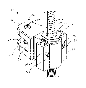
[0030] Referring to FIGS. 1-10, one embodiment of a structural fastener
constructed
according to the teachings of the present disclosure is generally indicated at
reference numeral
10. The structural fastener 10 includes a structure coupler, generally
indicated at 12, and a
threaded rod coupler, generally indicate at 14, configured to threadably
couple to a threaded rod
16 (e.g., an all threaded rod). The structure coupler 12 of the illustrated
structural fastener 10
comprises a beam clamp configured to couple to a structural beam (not shown).
It is understood
that in other embodiments, the structure coupler may be other types of
couplers configured to
couple to other load-bearing structural components. The illustrated beam clamp
12 includes
opposing, spaced apart first and second jaws 18, 20 (i.e., upper and lower
jaws as illustrated in
3
Date recue / Date received 2021-11-02
P20-1637CA01
BLN201637.US
the drawings) defining a jaw space 22 therebetween configured to receive a
flange of a beam
therein. At least one of the first and second jaws 18, 20 (e.g., each of the
jaws) defines a
threaded opening 24, 26 configured to threadably receive a set screw (not
shown) therein. The
set screw is configured to engage the flange of the beam received in the jaw
space 22 upon
tightening the set screw to couple the beam clamp 12 to the beam. The
illustrated jaws 18, 20
are generally rigid and extend outward (e.g., are cantilevered) from the
threaded rod coupler 14.
The beam clamp may be of other constructions, such as a beam clamp including
resiliently
deflectable jaws that snap into the beam.
[0031] The threaded rod coupler 14 includes housing 30, and a split nut,
generally
indicated at 32, captured within a cavity 34 of the housing. The housing 30 is
attached to the
structure coupler 12 and may be integrally formed therewith. As an example,
the housing 30 and
the structure coupler 12 may be made from metal, such as by casting, forging,
cutting, and other
metal working processes. The split nut 32 comprises separate first and second
nut portions,
generally indicated at 36, 38 (e.g., first and second nut halves). Each nut
portion 36, 38 includes
a nut body 40, 42 that is internally threaded, and a nut arm 44, 46 extending
outward from the
body. The nut bodies 40, 42 generally oppose one another within the housing 30
and are
movable toward and away from one another (upward and downward as illustrated)
to open and
close the split nut 32 when sliding the threaded rod 16 into the threaded rod
coupler 14, as
described in more detail below. When closed, the inner diameter of the split
nut 32 is suitable
for the split nut to be threadably received on the threaded rod 16. Pins 50,
52 coupled to the nut
arms 44, 46 are slidably received in slots 54, 56 defined by the housing 30.
The pins 50, 52 track
within the slots 54, 56 as the split nut 32 opens and closes. The pins 50, 52
are received in
openings 57, 58 (FIG. 7) in the nut arms 44, 46, although they may be coupled
to the split nut 32
in other ways. The slots 54, 56 diverge away from one another at a suitable
angle.
[0032] A through opening 60 for receiving the threaded rod 16 extends through
the
housing 30 and the cavity 34 and is generally aligned with the axis of the
inner diameter of the
split nut 32. In the illustrated embodiment, a bushing 64 defining a through
passage 66 is
threaded in a threaded lower portion 60A of the through opening below the
split nut 32, as
illustrated. The bushing 64 protects the threaded rod 16 from damage when
inserting the
threaded rod into the threaded rod coupling 14. The bushing 64 may be formed
from plastic or
other material. It is understood that in other embodiments the bushing may be
omitted.
4
Date recue / Date received 2021-11-02
P20-1637CA01
BLN201637.US
[0033] A lock 70 for selectively locking the split nut 32 in its closed
position is threaded
in an upper portion 60B of the through opening 60 above the split nut 32, as
illustrated. The lock
70 defines a through passage 74 generally aligned with the through opening 60.
A spring 78
(e.g., a compression spring, such as a coiled spring) is captured between the
lock 70 and the split
nut 32. When the lock 70 is threadably loosened in the through opening 60, the
split nut 32 is
biased in the closed position by force of the spring 78 and can be moved to
its open position
against the force of the spring. That is, the lock 70 provides a counter force
to the spring 78 to
bias the split nut 32 to its closed position while allowing the nut portions
36, 38 to move to open
the split nut. When the lock 70 is threadably tightened in the through opening
60, the split nut 32
is fixed in its closed position and inhibited from opening. That is, the split
nut 32 is closed and
the nut portions 36, 38 are inhibited from moving within the housing 30 when
the lock 70 is
threadably tightened. The lock 70 may be formed from plastic or other
material. The split nut
32 may be locked in its closed position in other ways.
[0034] The threaded rod coupler 14 provides quick-connect coupling to the
threaded rod
16 (e.g., the all threaded rod). To couple the threaded rod 16 to threaded rod
coupler 14, the lock
70 is initially loosened such that the spring 78 biases the split nut 32 in
its closed position. The
threaded rod 16 is inserted into the bushing 64 in the lower portion 60A of
the through opening
60 and the end of the threaded rod engages a lower surface of the split nut,
as shown in FIG. 3.
Continued insertion of the threaded rod 16 through the bushing 64 pushes the
nut portions 36, 38
upward against the force of the spring 78 so that the split nut 32 opens to
slidably receive the
threaded rod axially therein. The end of the threaded rod 16 enters the
through passage 74 of the
lock 70 as the threaded rod is pushed through the threaded rod coupler 14.
Once the structural
fastener 10 is slid on the threaded rod 16 to the desired longitudinal
position, the lock 70 is
tightened to inhibit the split nut 32 from opening. The structural fastener
110 threadably engages
the threaded rod 116 and can be rotated on the threaded rod 16 to further move
the structural
fastener to a desired longitudinal position on the threaded rod.
Second Embodiment
[0035] Referring to FIGS. 11-20, another embodiment of a structural fastener
constructed according to the teachings of the present disclosure is generally
indicated at
reference numeral 110. The structural fastener 110 includes a structure
coupler, generally
Date recue / Date received 2021-11-02
P20-1637CA01
BLN201637.US
indicated at 112, and a threaded rod coupler, generally indicate at 114,
configured to threadably
couple to a threaded rod 116. The structure coupler 112 of the illustrated
structural fastener 110
comprises a beam clamp configured to couple to a structural beam (not shown).
It is understood
that in other embodiments, the structure coupler may be other types of
couplers configured to
couple to other load-bearing structural components. The illustrated beam clamp
112 includes
opposing, spaced apart first and second jaws 118, 120 (i.e., upper and lower
jaws as illustrated in
the drawings) defining a jaw space 122 therebetween configured to receive a
flange of a beam
therein. At least one of the first and second jaws 118, 120 (e.g., each of the
jaws) defines a
threaded opening 124, 126 configured to threadably receive a set screw (not
shown) therein. The
set screw is configured to engage the flange of the beam received in the jaw
space 122 upon
tightening the set screw to couple the beam clamp 112 to the beam. The
illustrated jaws 118,
120 are generally rigid and extend outward (e.g., are cantilevered) from the
threaded rod coupler
114. The beam clamp may be of other constructions, such as a beam clamp
including resiliently
deflectable jaws that snap into the beam.
[0036] The threaded rod coupler 114 includes housing 130, and a split nut,
generally
indicated at 132, captured within a cavity 134 (FIG. 20) of the housing 130.
The housing 130 is
attached to the structure coupler 112 and may be integrally formed therewith.
As an example,
the housing 130 and the structure coupler 12 may be made from metal, such as
by casting,
forging, cutting, and other metal working processes. The split nut 132
comprises separate first
and second nut portions, generally indicated at 136, 138 (e.g., first and
second nut halves). Each
nut portion 136, 138 includes a nut body 140, 142 that is internally threaded,
and a nut arm 144,
146 extending outward from the body. The nut bodies 140, 142 generally oppose
one another
within the housing 130 and are movable toward and away from one another
(rotatable laterally
outward, as illustrated) to open and close the split nut 132 when inserting
the threaded rod 116
into the threaded rod coupler 114, as described in more detail below. When
closed, the inner
diameter of the split nut 132 is suitable for the split nut to be threadably
received on the threaded
rod 116. A spring (e.g., a wire spring), generally indicated at 178, received
in the cavity 134 of
the housing 130 biases the split nut 132 in its closed position (i.e., biases
the nut bodies 140, 142
toward one another). The illustrated nut arms 144, 146 pivot or rotate about
axes to allow the
split nut 132 to open and close. In the illustrated embodiment, the nut arms
144, 146 are
pivotally coupled to the spring 178 (e.g., a wire arm of the spring), although
the nut arms may be
6
Date recue / Date received 2021-11-02
P20-1637CA01
BLN201637.US
pivotably movable in other ways. The nut arms 144, 146 may be snap-fitting on
the wire spring
178.
[0037] A through opening 160 for receiving the threaded rod 116 extends
through the
housing 130 and the cavity 134 and is generally aligned with the axis of the
inner diameter of the
split nut 132. A lock 170 is threaded in an upper portion 160B of the through
opening 160 above
the split nut 132, as illustrated. The lock 170 defines a through passage 174
(FIG. 11) generally
aligned with the through opening 160. When the lock 170 is threadably loosened
in the through
opening 160, the split nut 132 is capable of moving to its open position
against the force of the
spring 178. When the lock 170 is threadably tightened in the through opening
160, the split nut
132 is fixed in its closed position and inhibited from opening. In particular,
when the lock 170 is
tightened, tabs 180 on the split nut 132 enter the through passage of the lock
174 (FIG. 17) to
inhibit the nut bodies 140, 142 from moving away from one another within the
housing 130. The
lock 170 may be formed from plastic or other material.
[0038] The threaded rod coupler 114 provides quick-connect coupling to the
threaded
rod. To couple the threaded rod 116 to threaded rod coupler 114, the lock 170
is initially
loosened such that the spring 178 biases the split nut 132 in its closed
position and the split nut is
allowed to open. The threaded rod 116 is inserted into the through opening 160
via a bottom
opening in the housing 130. The end of the threaded rod 116 engages a lower
surface of the split
nut 132. Continued insertion of the threaded rod 116 into the through opening
160 pushes the
nut bodies 140, 142 to pivot about the pivot connection of the nuts arms 144,
146, against the
force of the spring 178, so that the split nut 132 opens to slidably receive
the threaded rod axially
therethrough. The end of the threaded rod 116 slidably enters the through
passage 174 of the
lock 170 as the threaded rod is pushed through the threaded rod coupler 114 to
threadably engage
the rod. Once the structural fastener 110 is slid on the threaded rod 116 to
the desired location,
the lock 170 is tightened to inhibit the split nut 132 from opening. The
structural fastener 110
threadably engages the threaded rod 116 and can be rotated on the threaded rod
116 to further
move the structural fastener to a desired longitudinal position on the
threaded rod. As shown in
FIG. 16, the threaded rod coupler 114 may be disengaged from the threaded rod
116 by inserting
a tool 190 into the housing 130 and engaging depending arms 192, 194 of the
spring 178.
Pushing upward on the arms 192, 194 opens the spring 178 and, in turn, opens
the split nut 132.
7
Date recue / Date received 2021-11-02
P20-1637CA01
BLN201637.US
[0039] Having described embodiments of the invention in detail, it will be
apparent that
modifications and variations are possible without departing from the scope of
the invention
defined in the appended claims.
[0040] When introducing elements of the present invention or embodiment(s)
thereof,
the articles "a", "an", "the" and "said" are intended to mean that there are
one or more of the
elements. The terms "comprising", "including" and "having" are intended to be
inclusive and
mean that there may be additional elements other than the listed elements.
[0041] As various changes could be made in the above constructions, products,
and
methods without departing from the scope of the invention, it is intended that
all matter
contained in the above description and shown in the accompanying drawings
shall be interpreted
as illustrative and not in a limiting sense.
8
Date recue / Date received 2021-11-02