Note: Descriptions are shown in the official language in which they were submitted.
CA 03139002 2021-11-02
SCANNING DEVICE
CROSS-REFERENCE TO RELATED APPLICATIONS
[0001] Not applicable.
BACKGROUND
.. [0002] Dental aligners are plastic trays custom made to fit tightly over
the teeth of a user to force
the teeth to move to a desired location. Creating a three-dimensional model of
teeth is useful in
creating dental aligners. Conventional ways to create a three-dimensional
model of teeth include
making a physical impression of the teeth or taking an intraoral scan of the
teeth.
[0003] To make a physical impression of teeth, a patient must either go to the
office of an
orthodontic professional to take the impression or use an at-home dental
impression kit. To scan
teeth intraorally, the orthodontic professional inserts a scanning device into
the mouth of the
patient such that images of the teeth can be captured from inside the mouth.
Scanning teeth in
the office of an orthodontic or dental professional is inconvenient (e.g., the
user must travel to
the office), costly (e.g., the user must pay the professional for the
service), and limiting (e.g., if a
scan is incomplete or corrupted, the user must take time to travel back to the
office for an
additional scan). Using an at-home dental impression kit can be difficult for
a user to execute
properly, which can result in the need for repeat impressions.
[0004] A scanning device for a user to accurately scan the user's own teeth
without requiring a
visit to a dental or orthodontic professional is desirable to avoid the
complications associated
zo with physical impressions and scanning in a professional setting.
SUMMARY
[0005] An embodiment relates to a system comprising a scanning device operable
by a user to
scan teeth of the user to acquire images of the teeth. The scanning device
comprises a camera
operable to acquire the images, a guide configured to orient the camera with
respect
-1 -
Date recue /Date received 2021-11-02
CA 03139002 2021-11-02
WO 2020/227439 PCT/US2020/031720
to the teeth to facilitate acquisition of the images, and a server system
configured to receive
the images acquired by the scanning device and to develop a treatment plan for
the user based
on the received images.
[0006] Another embodiment relates to a scanning device comprising a body
configured to be
held by a user to scan teeth of the user to acquire images of the teeth. The
scanning device
also includes a camera operable to acquire the images and a guide configured
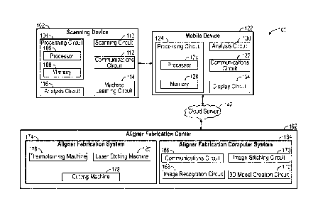
to orient the
camera with respect to the teeth to facilitate acquisition of the images. The
scanning device
also includes a communications circuit configured to communicate the images to
a server
system for development of a treatment plan for the user.
[0007] Another embodiment relates to a method comprising providing a scanning
device to a
user that is operable by the user to scan teeth of the user. The scanning
device comprises a
camera coupled to a body of the scanning device, the camera configured to
acquire images of
the teeth of the user. A guide is coupled to the body, the guide configured to
contact a guide
set of teeth and maintain the camera at a substantially constant distance from
a tooth being
scanned in a scanning set of teeth in the mouth of the user. The method
further comprises
communicating the images from the scanning device to a mobile device of the
user,
communicating the images from the mobile device of the user to a server
system, generating
an orthodontic treatment plan based on the images communicated to the server
system, and
manufacturing one or more aligners based on the orthodontic treatment plan.
BRIEF DESCRIPTION OF THE DRAWINGS
[0008] FIG. IA is a block diagram of a system for extraoral scanning of teeth,
according to
some embodiments.
[0009] FIG. 1B is an illustration of the mobile device of FIG lA in
communication with the
cloud server of FIG. 1A, according to some embodiments.
[0010] FIG. 2 is an illustration of a scanning device for scanning teeth,
according to some
embodiments.
[0011] FIGS. 3-4 are illustrations of a process for scanning teeth using the
scanning device of
FIG. 2, according to some embodiments.
-2-
CA 03139002 2021-11-02
WO 2020/227439 PCT/US2020/031720
[0012] FIG. 5 is an illustration of the teeth of a patient, according to some
embodiments.
[0013] FIG. 6 is an illustration of a high-resolution reconstruction of the
teeth of a patient,
according to some embodiments.
[0014] FIG. 7 is an illustration of a computer-generated mesh based on the
high-resolution
reconstruction of FIG. 6 is shown, according to some embodiments.
[0015] FIG. 8 is an illustration of an aligner, according to some embodiments.
[0016] FIGS 9-20 are illustrations of a mobile device application instructing
a patient how to
scan teeth using the scanning device of FIG. 2, according to some embodiments.
[0017] FIG. 21 is a flow diagram of a method for creating a dental aligner
using the scanning
device of FIG. 2, according to some embodiments.
[0018] FIG. 22 is a flow diagram of a method for creating a dental aligner
using the scanning
device of FIG. 2, according to some embodiments.
[0019] FIG. 23 is an illustration of a user scanning teeth for teledentistry
purposes using the
scanning device of FIG. 2, according to some embodiments.
[0020] FIG. 24 is an illustration of a mobile device application notifying a
patient of a dental
condition, according to some embodiments.
[0021] FIG. 25 is a flow diagram of a method for diagnosing a dental condition
using the
scanning device of FIG. 2, according to some embodiments.
[0022] FIGS. 26A-B are illustrations of various views of a scanning device,
according to
some embodiments.
[0023] FIG. 26C is an illustration of an exploded view of the scanning device
of FIGS. 26A-
B.
[0024] FIGS. 27A-B are illustrations of various views of another scanning
device, according
to some embodiments.
-3-
CA 03139002 2021-11-02
WO 2020/227439 PCT/US2020/031720
[0025] FIG. 27C is an illustration of an exploded view of the scanning device
of FIGS. 27A-
B.
[0026] FIGS 28A-B are illustrations of various views of another scanning
device, according
to some embodiments.
[0027] FIG. 28C is an illustration of an exploded view of the scanning device
of FIGS 28A-
B.
[0028] FIGS. 29A-B are illustrations of a front and a side view, respectively,
of an
arrangement of internal components in a scanning device, according to some
embodiments.
[0029] FIGS. 30A-B are illustrations of a front and a side view, respectively,
of another
arrangement of internal components in another scanning device, according to
some
embodiments.
[0030] FIG. 31 is an illustration of a jaw separation of a user with no
substantial head tilt,
according to some embodiments.
[0031] FIG. 32 is an illustration of a jaw separation of a user with a
substantial upward head
tilt, according to some embodiments.
[0032] FIG. 33 is an illustration of a jaw separation of a user with a
substantial downward
head tilt, according to some embodiments.
[0033] FIG. 34 is an illustration of a scanning device scanning teeth of a
user, according to
some embodiments.
[0034] FIG. 35 is an illustration of a guide of a scanning device, according
to some
embodiments.
[0035] FIGS. 36A-B is an illustration of the guide of FIG. 35 moving over
teeth, according to
some embodiments.
[0036] FIG. 37 is an illustration of another guide of a scanning device,
according to some
embodiments.
-4-
CA 03139002 2021-11-02
WO 2020/227439
PCT/US2020/031720
[0037] FIGS. 38A-B are illustrations of the guide of FIG. 37 moving over
teeth, according to
some embodiments.
[0038] FIG. 39 is an illustration of another guide of a scanning device,
according to some
embodiments.
[0039] FIGS. 40A-B are illustrations of the guide of FIG. 39 moving over
teeth, according to
some embodiments.
[0040] FIG. 41 is an illustration of another guide of a scanning device,
according to some
embodiments.
[0041] FIGS. 42A-B are illustrations of the guide of FIG. 41 moving over
teeth, according to
some embodiments.
[0042] FIG. 43 is an illustration of a case for a scanning device in one
configuration,
according to some embodiments.
[0043] FIG. 44 is an illustration of the case of FIG. 43 in another
configuration, according to
some embodiments.
[0044] FIG. 45 is a flow diagram of a method for creating a user account,
according to some
embodiments.
[0045] FIG. 46 is a flow diagram of a method for setting up a user account and
a scanning
device, according to some embodiments.
[0046] FIG. 47 is a continuation of the flow diagram of FIG. 46, according to
some
embodiments.
[0047] FIG. 48 is a flow diagram of a method for receiving scanned images,
according to
some embodiments.
[0048] FIG. 49 is a flow diagram of a method for a guest completing a scan,
according to
some embodiments.
[0049] FIG. 50 is a flow diagram of a method for generating an orthodontic
treatment plan,
according to some embodiments.
-5-
CA 03139002 2021-11-02
WO 2020/227439 PCT/US2020/031720
[0050] FIGS. 51A-D are illustrations of various configurations for storing and
using a
scanning device, according to some embodiments.
[0051] FIGS 52A-D are illustrations of additional configurations for storing
and using a
scanning device, according to some embodiments
[0052] FIGS. 53A-D are illustrations of further configurations for storing and
using a
scanning device, according to some embodiments
[0053] FIG. 54 is an illustration of another scanning device for scanning
teeth, according to
some embodiments.
DETAILED DESCRIPTION
[0054] Before turning to the figures, which illustrate certain exemplary
embodiments in
detail, it should be understood that the present disclosure is not limited to
the details or
methodology set forth in the description or illustrated in the figures. It
should also be
understood that the terminology used herein is for the purpose of description
only and should
not be regarded as limiting.
[0055] For a patient to begin a treatment plan using dental aligners, it is
beneficial to create a
three-dimensional ("3D") model of the teeth of the patient. As described, the
3-D model can
be generated using conventional impression techniques or a scanning device.
However, a
patient may need to visit an orthodontic professional to have the impressions
taken or teeth
scanned with the scanning device. In some instances, a patient may need to
visit a different
location where a scan is conducted by a professional that has been trained in
the scanning
process (e.g., a professional that is not a dental or orthodontic
professional). In another
example, a professional trained in the scanning process may bring a scanner to
the patient to
conduct a scan. A conventional scanner is generally large and can require
significant
structural support (e.g., attachment to a vehicle or a rolling cart, etc.). In
either instance, the
scan must be scheduled such that a professional trained in use of a scanner
(e.g., a dental or
orthodontic professional, an individual with specific training, etc.) can
conduct the scan of the
patient. A patient may therefore be more interested in scanning teeth with a
portable device
(e.g., a device that does not require structural support, and is significantly
lighter than a
conventional device such that the entire device can be held in the hand of the
patient) that can
-6-
CA 03139002 2021-11-02
WO 2020/227439 PCT/US2020/031720
be operated by the user (e.g., without assistance and/or direction from a
trained professional)
to scan teeth . Such a device provides the patient the ability to scan the
patient's teeth as the
patient desires. For instance, after conducting an initial scan, the patient
may desire to
conduct a subsequent scan. With a conventional scanner, the patient would have
to schedule
another scan and then wait until the scheduled date and time to conduct the
scan. With a
portable device, the patient can conduct subsequent scans as often as the
patient desires.
[0056] As used herein, the term "extraoral scan" refers to a scan of the teeth
of a patient
where the lens of the scanner does not enter the mouth of the patient. As used
herein, the
term "intraoral scan" refers to scanning the teeth by inserting a lens of a
scanning device
(e.g., a camera, a 3-D scanner, or any other scanning device that is capable
of capturing
images of the teeth) into the mouth to capture images of the teeth. As used
herein, the tettns
"user" and "patient" may be used interchangeably such that the user may be the
patient and
the patient may be the user. As used herein, the term "dental aligner" is
intended to cover any
type of dental appliance and can refer to any orthodontic device or device
intended for use in
a patient's mouth, including but not limited to dental aligners for
repositioning one or more
teeth of the patient, a denture, a mouth guard, or a retainer.
[0057] Referring to FIG. IA, a block diagram of a system 100 for scanning
teeth (e.g.,
intraorally or extraorally) is shown, according to some embodiments. The
system 100
includes a scanning device 102, a mobile device 122, a cloud server 142, and
an aligner
fabrication center 162.
[0058] The scanning device 102 can be any device configured to scan a 3D
surface.
Examples of the scanning device 102 include, but are not limited to, non-
contact active 3D
scanners (e.g., time-of-flight, triangulation, conoscopic holography, or any
other kind of non-
contact active 3D scanner), hand held laser 3D scanners, structured light 3D
scanners,
modulated light 3D scanners, and non-contact passive 3D scanners (e.g.,
stereoscopic,
photometric, silhouette, or any other kind of non-contact passive 3D scanner).
[0059] The scanning device 102 includes a processing circuit 104, a scanning
circuit 110, a
communications circuit 112, a machine learning circuit 114, and an analysis
circuit 116. The
processing circuit 104 is further shown to include a processor 106 and a
memory 108. The
processor 106 can be any type of processor capable of performing the functions
described
-7-
CA 03139002 2021-11-02
WO 2020/227439 PCT/US2020/031720
herein. The processor 106 may be a single or multi-core processor(s), digital
signal
processor, microcontroller, or other processor or processing/controlling
circuit. Similarly, the
memory 108 can be any type of volatile or non-volatile memory or data storage
capable of
performing the functions described herein. In operation, the memory 108 may
store various
data and software used during operation of the scanning device 102, such as
operating
systems, applications, programs, libraries, and drivers. The memory 108 is
communicatively
coupled to the processor 106 such that the processor 106 can execute files
located in the
memory 108.
[0060] The scanning circuit 110 is communicably coupled to the processor 106
and is
configured to conduct a scan of one or more objects. In this regard, the
scanning circuit 110
gathers images of the object(s) being scanned (e.g., the size, shape, color,
depth, tracking
distance, and other physical characteristics) such that the data can be
provided to other
circuits in the scanning device 102 (e.g., the analysis circuit 116 and the
machine learning
circuit 114). To appropriately scan the target objects, the scanning circuit
110 can include a
wide variety of sensors including, but not limited to, gyroscopes,
accelerometers,
magnetometers, inertial measurement units ("IMU"), depth sensors, and color
sensors.
[0061] The communications circuit 112 is communicably coupled to the scanning
circuit 110,
the machine learning circuit 114, and the analysis circuit 116 and is
configured to send
communications to, and receive communications from, the mobile device 122. For
example,
the communications circuit 112 can communicate information regarding the
sufficiency of a
scan to the mobile device 122 such that the mobile device 122 can display the
information to
the patient conducting the scan. As another example, the communications
circuit 112 can
provide images of the scan to the mobile device 122 in real time for the
mobile device 122 to
display to the patient during the scan. The communications circuit 112 can
communicate
with the mobile device 122 in a variety of ways including, but not limited to,
Bluetooth, a
WiFi network, a wired local area network (LAN), Zigbee, or any other suitable
way for
devices to exchange information.
[0062] The machine learning circuit 114 is configured to receive the images
gathered by the
scanning circuit 110 during a scan and determine characteristics of the scan.
For example,
the machine learning circuit 114 can determine, based on the images received,
whether the
patient initiated a scan from the correct location or whether the patient held
the scanning
-8-
CA 03139002 2021-11-02
WO 2020/227439 PCT/US2020/031720
device 102 in the correct orientation during the scan. The machine learning
circuit 114 is
also communicably coupled to the communications circuit 112 and is further
configured to
receive updates to improve the capabilities of the machine learning circuit
114.
[0063] The analysis circuit 116 is configured to receive information from the
scanning circuit
110 and the machine learning circuit 114 and analyze the information. For
example, the
analysis circuit 116 can receive image data from the scanning circuit 110 and
determine a
level of confidence that the scan being conducted by the patient will be
acceptable. As
another example, the analysis circuit 116 can merge multiple scans together
such that the
acceptable portions of the scans are combined to generate an acceptable scan.
The analysis
circuit 116 can provide the results of the analysis to the machine learning
circuit 114 and the
communications circuit 112.
[0064] The mobile device 122 can be any type of portable device configured to
run a mobile
application ("application"). As used herein, the term "application" refers to
software that can
be loaded on to a piece of hardware (e.g., the mobile device 122), where the
software
communicates with both the hardware and a server to perform the desired
functions.
Examples of the mobile device 122 include, but are not limited to, a mobile
phone, a tablet
computer, a laptop computer, a smart watch, a fitness tracker, and any other
Internet-
connected device that is capable of running an application. The mobile device
122 can be a
personal mobile device 122 of the patient. For example, the mobile device 122
can be the
patient's own mobile phone.
[0065] The mobile device 122 is shown to include a processing circuit 124, an
analysis
circuit 130, a communication circuit 132, and a display circuit 134. The
processing circuit
124 is further shown to include a processor 126 and a memory 128. The
processor 126 can
be any type of processor capable of performing the functions described herein.
The processor
126 may be a single or multi-core processor(s), digital signal processor,
microcontroller, or
other processor or processing/controlling circuit. Similarly, the memory 128
can be any type
of volatile or non-volatile memory or data storage capable of performing the
functions
described herein. In operation, the memory 128 may store various data and
software used
during operation of the mobile device 122, such as operating systems,
applications, programs,
libraries, and drivers. The memory 128 is communicatively coupled to the
processor 126
such that the processor 126 can execute files located in the memory 128.
-9-
CA 03139002 2021-11-02
WO 2020/227439 PCT/US2020/031720
[0066] The communication circuit 132 is communicably coupled to the analysis
circuit 130
and the display circuit 134 and is configured to send communications to, and
receive
communications from, the mobile device 122, and to send communications to, and
receive
communications from, the cloud server 142. For example, the communication
circuit 132 can
communicate information regarding images received from the scanning device 102
to the
cloud server 142 such that the cloud server 142 can perform further
operations. The
communication circuit 132 can communicate with the mobile device 122 and the
cloud server
142 in a variety of ways including, but not limited to, Bluetooth, a WiFi
network, a wired
local area network (LAN), Zigbee, or any other suitable way for devices to
exchange
information. In some embodiments, the communication circuit 132 includes a
radiofrequency transceiver to communicate with one or more radio towers to
transmit and/or
receive information using radio waves. In some embodiments, the radiofrequency
transceiver
includes a single band transceiver. In some embodiments, the radiofrequency
transceiver
includes a dual band transceiver.
[0067] The analysis circuit 130 is configured to receive information from the
communication
circuit 132 and analyze the information. For example, the communication
circuit 132 can
receive confidence level data from the scanning device 102 and provide the
data to the
analysis circuit 130. The confidence level data can be based on a comparison
of the accuracy
of the current scan to the accuracy of the scan of an average user. The
analysis circuit 130
can determine whether the patient is scanning more or less accurately
throughout the scan and
can provide the results of the analysis to the display circuit 134 and the
cloud server 142.
Additionally, the analysis circuit 130 is operable to perform additional
operations using the
images recorded by the scanning device 102. For example, the analysis circuit
130 can
determine the depth of the scan based on the information provided to it by the
scanning
device 102.
[0068] The display circuit 134 is configured to receive information from the
scanning device
102 and the analysis circuit 116 and display the information to the patient.
For example, the
display circuit 134 can receive information regarding the accuracy of the scan
being
performed. The display circuit 134 can provide the scan accuracy information
to the patient
by showing the scan accuracy information on the display of the mobile device
122. The
accuracy information can be provided as color coded information, where teeth
that have been
scanned successfully will show as green and teeth that have either been missed
or scanned
-10-
CA 03139002 2021-11-02
WO 2020/227439 PCT/US2020/031720
unsuccessfully will show as red. As another example, the display circuit 134
can receive
images of the teeth of the patient from the scanning device 102, and the
display circuit 134
can display the images of the teeth of the patient on the display of the
mobile device 122 in
real time as the patient scans the teeth.
[0069] The cloud server 142 is communicably coupled to the mobile device 122
and the
aligner fabrication center 162. In addition to being communicably coupled to
the mobile
device 122, the cloud server 142 can be communicably coupled to a plurality of
mobile
devices, with each of the plurality of mobile devices being communicably
coupled to a
separate scanning device. The cloud server 142 is configured to receive scan
data from the
mobile device 122 and perform additional operations on the data in order to
prepare the scan
data to send to the aligner fabrication center 162. The additional operations
the cloud server
142 can perfoim include, but are not limited to, high-resolution
reconstruction of scanned
images and converting the scanned images to one or more 3D images. The cloud
server 142
can communicate the results of the additional operations to the aligner
fabrication center 162.
[0070] In addition, the cloud server 142 is configured to analyze the data
received from the
plurality of mobile devices to which the cloud server 142 is communicably
coupled, and
provide the output of the analysis to the machine learning circuit 114 via the
mobile device
122. For example, the cloud server 142 may determine, based on the analysis of
a plurality of
scan data from various scans, that patients must hold the scanning device 102
within a certain
angular tolerance The cloud server 142 can provide that information to the
machine learning
circuit 114 (and the other machine learning circuits associated with the
plurality of mobile
devices connected to the cloud server 142) such that the scanning device 102
can ensure the
patient begins the scan with the scanning device 102 in the proper
orientation.
[0071] The aligner fabrication center 162 is communicably coupled to the cloud
server 142
and is configured to receive the 3D images from the cloud server 142 and
generate one or
more orthodontic aligners based on the 3D images. The aligner fabrication
center 162 is
shown to include an aligner fabrication computer system 164 and an aligner
fabrication
system 174. The aligner fabrication computing system 164 is configured to
determine, based
on the 3D images, the optimal way to reposition the teeth of the patient from
a first
configuration to a second configuration. The aligner fabrication computing
system 164
includes a communications circuit 166, an image recognition circuit 168, an
image stitching
-11-
CA 03139002 2021-11-02
WO 2020/227439 PCT/US2020/031720
circuit 170, and a 3D model creation circuit 172. The aligner fabrication
system 174 is
configured to create, based on one or more physical 3D models, one or more
aligners
operable to reposition the teeth of a patient
[0072] The communications circuit 166 is communicably coupled to the cloud
server 142
such that the cloud server 142 provides image data to the aligner fabrication
computer system
164 via the communications circuit 166. The communications circuit 166 can
also
communicate information to the cloud server 142 for the cloud server 142 to
provide to the
machine learning circuit 114 via the mobile device 122. For example, if the
images provided
to the aligner fabrication computer system 164 were not sufficient to generate
viable aligners,
the communications circuit 166 notifies the cloud server 142 of the
deficiency, the cloud
server 142 updates the machine learning circuit 114, and the machine learning
circuit 114
prevents similar deficiencies from being accepted in future scans.
[0073] The image recognition circuit 168 is operable to receive the image data
from the
communications circuit 166 and determine the location of the images for
further processing.
For example, the image recognition circuit can receive four images of the
mouth of a patient,
and the four images represent the scan of the entire mouth. The image
recognition circuit 168
can determine which image represents the lower right quadrant of the mouth,
the lower left
quadrant of the mouth, the upper right quadrant of the mouth, and the upper
left quadrant of
the mouth such that the image recognition circuit 168 organizes the images
such that the
images can be stitched together.
[0074] The image stitching circuit 170 receives the recognized images from the
image
recognition circuit 168 and stitches the images together to create images of
the top and
bottom teeth. In some embodiments, the image stitching circuit 170 creates one
image for the
top teeth and one image for the bottom teeth. In some embodiments, the image
stitching
circuit creates a single image that includes both the top teeth and the bottom
teeth. The image
stitching circuit 170 can implement any known method of stitching to stitch
the images
together. For example, the image stitching circuit 170 can stitch the images
together using
keypoint detection (e.g., finding distinct regions in images used to match
images together),
registration (e.g., matching features in images that minimize the sum of
absolute differences
between overlapping pixels), or any other known stitching method. The stitched
image is
provided to the 3D model creation circuit 172 for further processing.
-12-
CA 03139002 2021-11-02
WO 2020/227439 PCT/US2020/031720
[0075] The 3D model creation circuit 172 receives the stitched image and
creates a 3D model
from the stitched image. The 3D model creation circuit 172 can use any known
method of
generating a 3D model including, but not limited to, depth-based conversion,
depth from
motion, depth from focus, depth from perspective, or any other known method.
The 3D
model creation circuit 172 generates a treatment plan based on the 3D model of
the teeth of
the patient. The treatment plan includes a first tooth configuration based on
the 3D model of
the teeth, and a second tooth configuration based on an optimal tooth
configuration (e.g., the
treatment plan can include moving the teeth from a crooked configuration to a
straight
configuration). The 3D model creation circuit 172 determines a number of steps
in the
treatment plan required to move the teeth from the first configuration to the
second
configuration, and generates 3D models of the teeth for each step in the
treatment plan. The
3D model creation circuit 172 can also create physical representations of the
3D models via
any known method including, but not limited to, 3D printing, machining,
molding, or any
other method capable of creating a physical 3D model. The 3D model creation
circuit 172
sends the physical 3D models to the aligner fabrication system 174.
[0076] The aligner fabrication system 174 receives the physical 3D models from
the 3D
model creation circuit 172 and generates aligners for repositioning the teeth
of a patient. The
aligner fabrication system 174 includes a thermoforming machine 176, a cutting
machine
178, and a laser etching machine 180. The thermoforming machine is operable to
create an
aligner by placing a sheet of polymeric material on top of one or more 3D
models. The
polymeric material is heated and drawn tightly over the 3D models (e.g., via a
vacuum
system, a press, or any other known methods). The polymeric material is
allowed to cool,
and the thermoformed polymeric material is removed from the 3D model.
[0077] The cutting machine 178 receives the thermoformed polymeric material
from the
thermoforming machine 176 and is operable to trim excess polymeric material
from the
thermoformed polymeric material. The excess material is trimmed with a cutting
system
(e.g., using lasers, mechanical methods, or other known cutting methods) to
generate the
aligners.
[0078] The laser etching machine 180 is operable to include identification
marks on the
aligners via a laser etching process. The identification marks can include a
patient specific
-13-
CA 03139002 2021-11-02
WO 2020/227439 PCT/US2020/031720
number, a sequence number indicating how the aligner should be worn in
sequence with
other aligners, or any other type of marks that can provide an identifying
feature.
[0079] As described, the images recorded by the scanning device 102 can be
processed and
modified by the scanning device 102, the mobile device 122, the cloud server
142, and/or the
aligner fabrication center 162. In some embodiments, the images recorded by
the scanning
device 102 can be at least partially processed by a combination of at least
two or more of the
scanning device 102, the mobile device 122, the cloud server 142, or the
aligner fabrication
center 162 such that the combination of partial processing results in fully
processed and
modified images.
[0080] Referring to FIG. 1B, an illustration of the mobile device 122 of FIG.
1A in
communication with the cloud server 142 of FIG. 1A is shown, according to some
embodiments. A tower network 181 includes a plurality of towers (e.g., towers
182-186).
The towers 182-186 can be referred to as cellular towers, radio towers, base
stations, base
transceiver stations, etc., and include equipment for cellular communication.
For example,
the towers 182-186 can include various antennae, transmitters, receivers,
transceivers, digital
signal processors, control electronics, global positioning receivers, and
electrical power
sources. The towers 182-186 are configured such that each of the towers 182-
186 can send
and receive signals within a specified area (e.g., a cell). Typically, the
area in which each of
the towers 182-186 can send and receive signals is shaped approximately like a
hexagon. For
example, the tower 182 can send and receive signals (e.g., data) within the
area 192, the
tower 183 can send and receive signals within the area 193, the tower 184 can
send and
receive signals within the area 194, the tower 185 can send and receive
signals within the
area 195, and the tower 186 can send and receive signals within the area 196.
[0081] To send a signal from an originating location to a destination
location, each tower can
send a signal to a tower within an adjacent area. For example, the tower 182
can send a
signal to the tower 183 because the area 193 is adjacent to the area 192.
Additionally, the
tower 182 can send a signal to the tower 185 because the area 195 is adjacent
to the area 192.
[0082] As described with reference to FIG. 1A, the communication circuit 132
of the mobile
device 122 sends signals (e.g., radio signals containing data related to a
scan) from the mobile
device 122 to communicate with the cloud server 142. In an example embodiment,
the signal
-14-
CA 03139002 2021-11-02
WO 2020/227439 PCT/US2020/031720
originates from the communication circuit 132 of the mobile device 122.
Because the mobile
device 122 is within the area 192, the signal reaches the tower 182. From the
tower 182, the
signal is sent to the tower 183 because the area 193 is adjacent to the area
192, and from the
tower 183 the signal is sent to the tower 184 because the area 194 is adjacent
to the area 193.
The signal is then sent from the tower 184 to the cloud server 142 because the
cloud server
142 is located within the area 194.
[0083] In some embodiments, the signals sent by the mobile device 122 include
multiple
digital signals, multiple analog signals, or a combination of multiple digital
and analog
signals. In such embodiments, the multiple signals are combined into one
signal using
multiplexing protocols to reduce the resources required to send the signal. In
an example
embodiment, frequency division multiplexing (FDM) can be used to combine the
signals. In
FDM, each user is assigned a different frequency from the complete frequency
spectrum such
that all frequencies can travel simultaneously. In another example embodiment,
time division
multiplexing (TDM) can be used to combine the signals. In TDM, a single radio
frequency is
divided into multiple slots and each slot is assigned to a different user such
that multiple users
can be supported simultaneously. In yet another example embodiment, code
division
multiplexing (CDMA) can be used to combine the signals. In CDMA, several users
share the
same frequency spectrum simultaneously and are differentiated via unique codes
assigned to
each user. The receiver is supplied with the unique keys such that the user
can be identified
by the receiver.
[0084] In some embodiments, the signal is sent via a packet switching process.
In a packet
switching process, the signal (e.g., the data being sent) is divided into
smaller parts called
packets. The packets are then sent individually from the source (e.g., the
mobile device 122)
to the destination (e.g., the cloud server 142). In some embodiments, each
packet can follow
a different path to the destination, and the packets can arrive out of order
at the destination,
where the packets are assembled in order (e.g., the datagram approach). In
some
embodiments, each packet follows the same path to the destination, and the
packets arrive in
the correct order (e.g., the virtual circuit approach).
[0085] Accordingly, any data acquired by the scanning device 102 can be
communicated to
the cloud server 142 or the aligner fabrication center 162 by way of or not by
way of cloud
server 142 using the tower network 181. In some embodiments, any data acquired
by the
-15-
CA 03139002 2021-11-02
WO 2020/227439 PCT/US2020/031720
scanning device 102 can be communicated using one or more towers 182-186 of
the tower
network 181. For example, 3D images of the user's teeth captured by the
scanning device 102
can be communicated to the cloud server 142 or the aligner fabrication center
162 by way of
one or more towers the 182-186 of the tower network 181. Additionally, 3D
images of the
user's teeth captured by the scanning device 102 can be communicated directly
to other
locations (e.g., the office of a dental professional, etc.) by way of one or
more of the towers
182-186 for diagnostic purposes, treatment purposes, or any other purpose. In
some cases,
communicating 3D image data over the tower network 181 is advantageous over
other
methods of communication. For example, the 3D image data can be more
efficiently
communicated when broken up into smaller sized packets or smaller file sizes
and separately
communicated over the tower network 181 rather than being communicated in a
large file
size or larger packets when using other methods of communication.
[0086] Referring now to FIG. 2, an illustration of the scanning device 102 for
scanning teeth
is shown, according to some embodiments. The scanning device 102 can be any
known
device capable of capturing images of a 3D object for the purpose of creating
a 3D model. In
an example embodiment, the scanning device 102 is configured to capture images
of a 3D
object based on a "depth from stereo" concept (e.g., the depth of the 3D
object is determined
by comparing images obtained from at least two cameras positioned at angles to
the 3D
object) The scanning device 102 includes a body 202, a front portion 204, a
first camera 206,
a second camera 208, a projector 207, a guide bar 210, and a guide tip 212.
The body 202 is
sized and configured to be held in the hand of a patient during a scan of the
teeth of the
patient. In another embodiment, a person other than the patient having their
teeth being
scanned can hold and operate the scanning device 102 to scan the teeth of the
patient. The
body 202 can be manufactured from a plastic material (e.g., polycarbonate,
polyethylene, or
any other suitable plastic), a metal material (e.g., aluminum, stainless
steel, or any other
suitable metal), or any other material suitable for the application.
[0087] The first camera 206 and the second camera 208 are spaced apart and
secured to the
body 202 such that the lenses of the first camera 206 and the second camera
208 extend
beyond the front portion 204. In some embodiments, the first camera 206 and
the second
camera 208 can be equivalent cameras. For example, the first camera 206 and
the second
camera 208 can be two-dimensional cameras that capture two-dimensional images
along with
some depth information. In some embodiments, the first camera 206 and the
second camera
-16-
CA 03139002 2021-11-02
WO 2020/227439 PCT/US2020/031720
208 can be different cameras. For example, the first camera 206 can be a two-
dimensional
camera that captures depth information, and the second camera 208 can be a 3D
camera.
[0088] The projector 207 is shown to be located in between the first camera
206 and the
second camera 208; however, the projector 207 can be located anywhere on the
body 202.
The projector 207 receives the images from the first camera 206 and the second
camera 208
and overlays the images from the first camera 206 and the second camera 208.
The overlaid
images are provided to the analysis circuit 116 and the analysis circuit 116
can
stereoscopically calculate the depth of the images from the first camera 206
and the second
camera 208. In some embodiments, the projector 207 includes a light source and
the
projector 207 projects light from the light source toward the object being
scanned. The light
source can be, for example, a near infrared light, a light in the visible
spectrum (e.g., light
with a wavelength between approximately four hundred and approximately seven
hundred
nanometers). In some embodiments, the light source is a light with a
wavelength of between
approximately three hundred eighty nanometers and five hundred nanometers.
[0089] The scanning device 102 may also include a light source 214 to project
light on the
surface for scanning. In some embodiments, the light source 214 can project
visible light
onto the surface for scanning (e.g., blue light or any other type of visible
light). In some
embodiments, the light source 214 can project infrared light (or other non-
visible light, e.g.
near-infrared light) onto the surface for scanning. The light source 214 can
be turned on prior
to the scanning procedure, either by the user (e.g., via a button, switch, or
other type of
actuator that can open or close a circuit coupled to the light source 214) or
automatically.
[0090] In some embodiments, the scanning device 102 includes sensors 216 to
receive light
reflected from the surfaces being scanned. In some embodiments, the sensors
216 are
configured to receive infrared light (or other non-visible light) reflected
from the surfaces
being scanned. In some embodiments, the sensors 216 are configured to receive
visible light
(e.g., blue light or any other type of visible light) reflected from the
surfaces being scanned.
In embodiments where the light source 214 is turned on automatically, the
sensors 216 can be
configured to detect the motion and/or orientation of the scanning device 102.
When the
sensors 216 detect motion indicative of a scanning procedure (e.g., the
scanning device 102 is
oriented at a certain angle or angles, the scanning device 102 is moved
according to a certain
-17-
CA 03139002 2021-11-02
WO 2020/227439 PCT/US2020/031720
pattern, etc.) the sensors 216 send a signal to the light source 214 such that
the light source
214 turns on.
[0091] In some embodiments, the scanning device 102 may include bone scanning
technology. Bone scanning technology may include various systems and methods
to scan the
exterior and interior of a bone. For example, in a dental environment, a bone
scan may
provide information regarding the internal health of teeth. A bone scan may
also provide
information regarding the health of the roots of the teeth, or other portions
of the teeth that
may not be visible such that they cannot be scanned by a conventional scanning
device. In
some embodiments, the bone scanning technology enables acquisition of the
shape of teeth
roots and the position of teeth roots with respect to one another, teeth of
the user, or a
jawbone of the user.
[0092] The guide 210 extends from the front portion 204 and defines a guide
tip 212, where
the guide tip 212 is located at the end of the guide 210 opposite the front
portion 204. The
guide 210 can be constructed from the same material as the body 202; however,
the guide
210 can also be constructed from different materials. The guide 210 is
operable to extend
between the teeth of a patient and the body 202 during a scan of the teeth of
the patient,
therefore the guide 210 is substantially rigid such that the body 202 can be
maintained at a
substantially constant distance (e.g., between 2-6 centimeters (cm), around 3
cm, around 4
cm, etc.) from the teeth of the patient during the scan.
[0093] The guide tip 212 is operable to contact the teeth of the patient
throughout the scan
such that the body 202 can be maintained at a substantially constant distance
from the teeth of
the patient during the scan. As shown, the guide tip 212 is a flat surface;
however, the guide
tip 212 can be any shape that directs the patient to maintain contact between
the guide tip 212
and the teeth during a scan. For example, the guide tip 212 can be shaped like
a "V" such
that the teeth can be inserted into the "V" to maintain contact throughout the
scan. As
another example, the guide tip 212 can be shaped like a "U" such that the
teeth can be
inserted into the "U" to maintain contact throughout the scan. The guide tip
212 can be
oriented in any configuration to promote accurate scanning. For example, in
the embodiment
where the guide tip 212 is "V" shaped, the "V" can be oriented such that the
opening of the
"V" is facing down (e.g., away from the first camera 206 and the second camera
208). As
another example, in the embodiment where the guide tip 212 is "U" shaped, the
"U" can be
-18-
CA 03139002 2021-11-02
WO 2020/227439 PCT/US2020/031720
oriented such that the opening of the "U" is facing up (e.g., toward the first
camera 206 and
the second camera 208).
[0094] In embodiments where the scanning device 102 scans structures inside of
a mouth
(e.g., teeth, gums, etc.), the scanning device 102 is preferably capable of
scanning at a
resolution of approximately 100 microns when scanning an individual tooth.
Furthermore,
the scanning device 102 is preferably capable of a resolution of approximately
300 microns
when conducting a cross-arch scan (e.g., scanning all the upper teeth or all
the lower teeth).
In some embodiments, the scanning resolution is preferably greater (e.g.,
between
approximately 50-100 microns when scanning an individual tooth and between
approximately 100-300 microns when conducing a cross-arch scan).
[0095] Referring to FIGS. 3-4, illustrations of a process for scanning teeth
using the scanning
device 102 of FIG. 2 are shown, according to some embodiments. As shown in the
figures, a
patient 302 has upper teeth 306 and lower teeth 308, and the patient 302
desires to receive
and use aligners to move the upper teeth 306 and the lower teeth 308 such that
they look
straighter. To begin the aligner creation process, the patient 302 is sent the
scanning device
102 to scan the upper teeth 306 and the lower teeth 308. The patient 302 is
also instructed to
download an application to the mobile device 122 (not shown). The mobile
device 122
provides instructions to the patient 302 regarding how to properly conduct a
scan of the teeth.
The instructions to the patient 302 will be described in more detail with
reference to FIGS. 9-
20.
[0096] To generate a scan of the teeth, the patient 302 places the guide tip
212 in a specific
section of the mouth, as instructed. For example, the guide tip 212 may be
positioned on the
back molar on the right side of lower teeth 308 to begin the scan. By placing
the guide tip
212 on the lower teeth 308, the scan of the teeth will begin by scanning in
the scanning area
310 (e.g., the upper teeth 306) to prevent the scanning device 102 from
confusing the guide
tip 212 with the teeth to be scanned. After the scan begins, the patient 302
moves the
scanning device 102 around the mouth in the direction of the arrow 312 while
keeping the
guide tip 212 in contact with the lower teeth 308. As the patient 302 moves
the scanning
device 102 around the mouth, the first camera 206 and the second camera 208
record images
of the upper teeth 306. The patient 302 moves the scanning device 102 until
the guide tip
-19-
CA 03139002 2021-11-02
WO 2020/227439 PCT/US2020/031720
212 contacts the back molar on the left side of the lower teeth 308. The scan
of the upper
teeth 306 is complete.
[0097] The patient rotates the scanning device 180 degrees and places the
guide tip 212 in a
specific section of the mouth, as instructed. For example, the guide tip 212
may be
positioned on the back molar on the right side of upper teeth 306 to begin the
scan of the
lower teeth 308. With the scanning device 102 oriented in this manner, the
scanning area 310
is focused on the lower teeth 308. The patient 302 moves the scanning device
102 around the
mouth in the direction of the arrow 312 while keeping the guide tip 212 in
contact with the
upper teeth 306. As the patient 302 moves the scanning device 102 around the
mouth, the
first camera 206 and the second camera 208 record images of the lower teeth
308. The
patient 302 moves the scanning device 102 until the guide tip 212 contacts the
back molar on
the left side of the upper teeth 306. The scan of the lower teeth 308 is
complete.
[0098] In some embodiments, the guide 210 is not included on the scanning
device 102. In
such embodiments, the scanning device 102 may be inserted into the mouth to
bring the
camera 206 and the camera 208 closer to the teeth for scanning. In some
embodiments, the
guide 210 is included on the scanning device 102, but the user can determine
whether to use
the guide 210 or insert the scanning device 102 into the mouth to scan the
teeth.
[0099] In some embodiments, after the scan of the lower teeth 308 and the
upper teeth 306 is
complete, the images are sent to the cloud server 142 for further processing.
In some
embodiments, the images are sent to the cloud server 142 in batches. For
example, after
scanning the right quadrant of the upper teeth 306, the images of the right
quadrant of the
upper teeth 306 are sent to the cloud server 142. Furthermore, after scanning
the left
quadrant of the upper teeth 306, the images of the left quadrant of the upper
teeth 306 are sent
to the cloud server 142. In embodiments where the images are sent to the cloud
server 142 in
batches, the patient 302 may be instructed to stop scanning at certain points
to allow the
images to be sent to the cloud server 142. For example, after scanning the
right quadrant of
the upper teeth 306, the patient 302 may be instructed to stop the scan to
allow the images to
be sent to the cloud server 142, and then instructed to begin the scan again
after the images
are sent.
-20-
CA 03139002 2021-11-02
WO 2020/227439 PCT/US2020/031720
[0100] Referring to FIG. 5, an illustration of the upper teeth 306 of the
patient 302 are
shown, according to some embodiments. The upper teeth 306 includes an upper
right
quadrant 402 and an upper left quadrant 404. In embodiments where the patient
scans teeth
in batches, the first camera 206 and the second camera 208 can record two-
dimensional
images of the upper right quadrant 402 during a first portion of the scan and
the upper left
quadrant 404 during a second portion of the scan. As described, the projector
207 can
combine the images from the first camera 206 and the second camera 208 to
create 3D
images of the upper right quadrant 402 and the upper left quadrant 404, and
the 3D images of
the upper right quadrant 402 and the upper left quadrant 404 are provided to
the cloud server
142 for high-resolution reconstruction.
[0101] Referring to FIG. 6, an illustration of a high-resolution
reconstruction 420 of the teeth
of a patient 302 is shown, according to some embodiments. For example, the
high-resolution
reconstruction 420 may be a portion of the upper right quadrant 402 of FIG. 5.
The high-
resolution reconstruction 420 includes a first tooth 422, a second tooth 424,
and a third tooth
426. After the cloud server 142 receives the 3D images of the upper right
quadrant 402, the
cloud server 142 generates the high-resolution reconstruction 420 of the first
tooth 422, the
second tooth 424, and the third tooth 426 such that attributes like the shape,
depth, and angles
of each tooth can be converted to a 3D model for creation of an aligner.
[0102] Referring to FIG. 7, an illustration of a computer-generated mesh 440
based on the
high-resolution reconstruction 420 of FIG. 6 is shown, according to some
embodiments. The
cloud server 142 provides the high-resolution reconstruction 420 to the
aligner fabrication
center 162 to create one or more aligners. The aligner fabrication center 162
can receive
more than one high-resolution reconstruction (including the high-resolution
reconstruction
420) such that the image recognition circuit 168 and the image stitching
circuit 170 can create
a 3D image of the full set of teeth (e.g., the top teeth 306). The 3D image is
provided to the
3D model creation circuit 172 to create the 3D model of the teeth. The 3D
model creation
circuit 172 analyzes the 3D image and generates the computer generated mesh
440 that
includes a first tooth mesh 442, a second tooth mesh 444, and a third tooth
mesh 446. The
first tooth mesh 442, second tooth mesh 444, and third tooth mesh 446 include
a plurality of
nodes that correspond to features on the surfaces of the teeth (e.g., bumps,
angles, ridges,
etc.). The computer generated mesh 440 is used to generate the 3D model of the
teeth, which
is then 3D printed to generate a physical 3D model. The computer generated
mesh 440, as
-21-
CA 03139002 2021-11-02
WO 2020/227439 PCT/US2020/031720
shown, includes only three teeth for purposes of example. A full 3D image of
the teeth can
be used to generate a full computer generated mesh of the teeth, which can be
used to
generate a full 3D model of the teeth.
[0103] Referring to FIG. 8, an illustration of an aligner 500 is shown,
according to some
embodiments. The aligner 500 includes an upper right quadrant 502 that
corresponds to the
upper right quadrant 402 of FIG. 5, and an upper left quadrant 504 that
corresponds to the
upper left quadrant 404 of FIG. 5. After the physical 3D model of the teeth is
printed by the
3D model creation circuit 172, the physical 3D model is received by the
aligner fabrication
system 174. A sheet of a polymeric material is used to create the aligner 500
using the
thermoforming machine 176, the cutting machine 178, and the laser etching
machine 180, as
described.
[0104] In some embodiments, a plurality of aligners is created, with each
aligner including a
slightly different geometry such that the aligner forces the teeth to be
gradually repositioned.
In embodiments where a plurality of aligners is created, the upper right
quadrant 502 and the
upper left quadrant 504 may have geometries slightly different from the upper
right quadrant
402 and upper left quadrant 404. When the patient 302 inserts, for example,
the upper teeth
306 into the aligner 500, the aligner 500 may exert forces on the upper teeth
306 that cause
the upper teeth 306 to move.
[0105] Referring to FIGS. 9-20, illustrations of a mobile device application
600 instructing
the patient 302 how to scan teeth using the scanning device 102 of FIG. 2 is
shown,
according to some embodiments. As described, the patient 302 is instructed to
download the
application 600 to the mobile device 122. The mobile device 122 includes a
display 602 that
can display messages to the patient 302 before, during, and after the scan.
[0106] After the patient 302 installs the application 600 on the mobile device
122, the patient
302 initiates the application 600 to begin the scanning process. Upon
initiating the
application 600, the application 600 displays a message 604 on the display 602
asking the
patient 302 if the patient 302 is ready to being the scanning process. If the
patient 302 selects
the no button 606, the application 600 may close or direct the patient 302 to
begin the
application 600 again when the patient 302 is ready to begin scanning. If the
patient 302
selects the yes button 608, the mobile application 600 will move to the next
screen.
-22-
CA 03139002 2021-11-02
WO 2020/227439 PCT/US2020/031720
[0107] The mobile application 600 displays a message 608 regarding the initial
position of
the scanning device 102 relative to the teeth of the patient 302. As shown in
image 610 of
FIG. 10, in some embodiments the patient 302 does not need to use a device to
spread the lips
apart to begin the scan. As shown in image 614 of FIG. 11, in some embodiments
the user
needs to insert a device into the mouth to spread the lips apart to begin the
scan. When the
patient 302 is ready to begin the scan, the patient 302 is holding the
scanning device 102 in
one hand and the mobile device 122 in the other hand such that the patient 302
can view the
display 602 while conducting the scan with the scanning device 102.
[0108] As shown, the patient 302 can conduct the scan of teeth using the guide
210 so the
camera 206 and the camera 208 do not enter the mouth. However, the patient can
also
conduct the scan of the teeth by inserting the scanning device 102 into the
mouth to scan the
teeth, as described.
[0109] The mobile application 600 displays a message 616 prompting the patient
302 to
begin the scan by pressing the start button 618. Upon pressing the start
button 618, the
message 620 is displayed to provide the patient 302 with instructions as to
how to conduct the
scan. An image 622 is also shown on the display to guide the patient 302
during the scan. In
some embodiments, the image 622 is a short video showing the patient 302 how
to conduct
the scan. In some embodiments, the scanning device 102 communicates its
position to the
mobile application 600 in real time such that the display 602 can superimpose
an image of the
scanning device 102 with the image 622 and the patient 302 can attempt to
match the position
on the image to provide for a more accurate scan In some arrangements, a
confidence level
is shown on the display 602. The confidence level provides the user with real
time feedback
regarding the accuracy of the scan. For example, the display 602 may indicate
that the
confidence level during the scan is 40%. Furthermore, the message may be
highlighted in red
to indicate that the confidence level is low for an accurate scan. As another
example, the
display 602 may indicate that the confidence level during the scan is 95%, and
the message
may be highlighted in green to indicate that the confidence level is high for
an accurate scan.
The scanning device 102 or application may alert the scanner when the
confidence level does
not meet a threshold (e.g., an audio, visual, or tactile alert when the
confidence level is less
than 95%).
-23-
CA 03139002 2021-11-02
WO 2020/227439 PCT/US2020/031720
[0110] After the scan of the first set of teeth is complete, the application
provides a message
624 to the patient 302 instructing the patient 302 to orient the scanning
device 102 to scan the
other set of teeth. The message 628 is displayed to provide the patient 302
with instructions
as to how to conduct the scan. An image 630 is also shown on the display to
guide the
patient 302 during the scan. In some embodiments, the image 630 is a short
video showing
the patient 302 how to conduct the scan. In some embodiments, the scanning
device 102
communicates its position to the mobile application 600 in real time such that
the display 602
can superimpose an image of the scanning device 102 with the image 630 such
that the
patient 302 can attempt to match the position on the image to provide for a
more accurate
scan. As described, confidence information can also be displayed in real time
during the
scan.
[0111] In some embodiments, the scan may not be successful. In such
embodiments, the
scanning device 102 provides the application 600 with data regarding the
portion(s) of the
scan that were unsuccessful, and the application 600 provides the patient 302
with the
message 632 indicating that the scan was unsuccessful. An image 634 provides a
highlighted
section 636 to indicate to the user the specific portion of the scan that was
unsuccessful. The
patient 302 can then initiate a new scan in attempts to correct the
deficiency.
[0112] ln some arrangements, as shown in FIG. 17, the scanning device 102 may
provide the
mobile application 600 with data in real time related to the appearance of the
teeth being
scanned by the patient 302 In such arrangements, the mobile application 600
can display an
image 640 that includes the teeth 642 of the patient 302 instead of the
generic teeth as shown
in, for example, image 630 of FIG. 5. Additionally, the image 640 can include
a highlighted
section 642 that can indicate, in real time, whether the scan of a particular
section of the teeth
was successful. For example, in some embodiments the highlighted section 642
can be
green, indicating a successful scan. In some embodiments, the highlighted
section 642 can be
red, indicating an unsuccessful scan. In some embodiments, the highlighted
section 642 can
include a combination of red and green, indicating that some portions of the
scan are
acceptable, and some portions of the scan are unacceptable.
[0113] When the scan is complete, a message 646 is provided to the patient 302
to advise the
patient that the scan is being evaluated to determine whether it is acceptable
or unacceptable.
-24-
CA 03139002 2021-11-02
WO 2020/227439 PCT/US2020/031720
During this time, the scan data may be sent to the cloud server 142 to verify
whether the scan
is acceptable.
[0114] The patient 302 receives a message 648 indicating that the scan was
successful, or the
patient 302 receives a message 650 indicating that the scan was unsuccessful
and that a new
scan should be started by pressing the start scan button 652.
[0115] Referring to FIG. 21, a flow diagram of a method 700 for creating a
dental aligner
using the scanning device 102 of FIG. 2 is shown, according to some
embodiments. At 702,
a tooth scanning device is paired with a mobile device. For example, the
scanning device 102
is paired with the mobile device 122. In some embodiments, the scanning device
102 and
mobile device 122 are paired using Bluetooth technology. In some embodiments,
other
known pairing methods can be used that would provide for communication between
the
scanning device 102 and the mobile device 122.
[0116] At 704, a tooth scanning application on the mobile device 122 is
opened. For
example, after downloading the application 600 to the mobile device 122, the
patient 302
opens the application 600 on the mobile device 122.
[0117] At 706, the guide 210 is placed on the bottom teeth on one side of the
mouth. For
example, as shown in FIG. 3, the patient 302 places the guide tip 212 of the
guide 210 on the
lower teeth 308 in preparation for the scan.
[0118] At 708, the scan is started. For example, as shown in FIG. 12, after
properly
positioning the scanning device 102 by placing the guide 210 on the lower
teeth 308, the
patient 302 can start the scan by pressing the start scan button 618 on the
mobile device 122.
[0119] At 710, the scanning device 102 is moved from one side of the mouth to
the other.
For example, as shown in FIG. 4, the scanning device 102 is moved in the
direction of the
arrow 312 such that the scanning device 102 scans the upper teeth 306.
[0120] At 712, the scanning device 102 is turned over and the guide 210 is
placed on the
upper teeth 306. For example, the patient 302 places the guide tip 212 of the
guide 210 on
the upper teeth 306 on one side of the mouth.
-25-
CA 03139002 2021-11-02
WO 2020/227439 PCT/US2020/031720
[0121] At 714, the scanning device 102 is moved from one side of the mouth to
the other.
For example, as shown in FIG. 4, the scanning device 102 is moved in the
direction of the
arrow 312 such that the scanning device 102 scans the lower teeth 308.
[0122] At 716, a determination is made as to whether the scan is acceptable.
The
determination can be made by either the scanning device 102 or the cloud
server 142. In
either case, if the scan is not acceptable, at 718 feedback is provided
regarding the scan. For
example, as shown in FIG. 16, a specific area or areas of the teeth of the
patient 302 may be
highlighted as one or more areas that were not scanned successfully. If the
scan is
acceptable, at 720 the scan is sent to the aligner fabrication center 162 for
further analysis.
For example, the image recognition circuit 168 determines and/or verifies the
images from
the scan correspond to the correct portions of the mouth (e.g., the image of
the upper right
quadrant of the mouth is actually the upper right quadrant of the mouth).
[0123] At 722, the images are stitched together to create a single image. For
example, the
image stitching circuit 170 stitches multiple images of the teeth together to
create one 3D
image of the top teeth and one 3D image of the bottom teeth from the scan. In
some
embodiments, a single 3D image including both the top teeth and the bottom
teeth is created.
In some embodiments, a single 3D image of the top teeth in contact with the
bottom teeth
(e.g., bite articulation) is created based on one or more scans conducted with
the top teeth and
bottom teeth in a bite articulation position.
[0124] At 724, a treatment plan is created based on the 3D image of the teeth.
For example,
the 3D image of the teeth of the patient 302 is compared to the 3D image of
straightened
teeth, and the aligner fabrication computer system 164 determines the number
of aligners
needed to move the teeth from the initial configuration to the straightened
configuration.
[0125] At 726, one or more 3D models of the teeth are created. For example,
the 3D model
creation circuit 172 generates a mesh similar to the mesh 440 of FIG. 7 such
that a physical
3D model of the teeth can be created by any known method (e.g., 3D printing,
molding, etc.).
Physical 3D models are created for each step in the treatment plan.
[0126] At 728, aligners are manufactured from the 3D models. For example,
aligners are
manufactured using the thermoforming machine 176, the cutting machine 178, and
the laser
etching machine 180, as described. Aligners can be manufactured singly, or in
batches.
-26-
CA 03139002 2021-11-02
WO 2020/227439 PCT/US2020/031720
When manufactured in batches, a plurality of physical 3D models are arranged
such that a
large sheet of polymeric material fits over all the physical 3D models. The
polymeric
material is heated and formed to the physical 3D models to create the
aligners, as described.
[0127] Referring to FIG. 22, a flow diagram of a method 800 for creating a
dental aligner
using the scanning device 102 of FIG. 2 is shown, according to some
embodiments At 802,
a scanning device is sent to a patient. For example, the scanning device 102
is sent to the
patient 302.
[0128] At 804, a mobile application is provided to the patient 302. For
example, when the
patient 302 receives the scanning device 102, the patient is instructed to
download the mobile
application 600 in order to properly use the scanning device 102.
[0129] At 806, the patient is directed to use the scanning device 102 with the
mobile
application 600. For example, as shown in FIGS. 9-20, the mobile application
600 provides
step-by-step instructions to the patient 302 on how to properly scan teeth.
The mobile
application 600 also provides feedback from the scanning device 102 regarding
the
acceptability of the scan.
[0130] At 808, data from the scanning device 102 is received via the mobile
device 122. For
example, when the scan is complete, the scanning device 102 provides the image
data to the
mobile device 122, and the mobile device 122 provides the image data to the
cloud server
142. In some embodiments, the image data is provided to the cloud server 142
in batches
(e.g., after one quadrant of teeth is scanned) instead of after all teeth have
been scanned.
[0131] At 810, a treatment plan is determined based on the image data. For
example, the
aligner fabrication computer system 164 compares the scanned images to images
of an ideal
smile and determines the number of aligners required to move the teeth of the
patient 302 to
match the ideal smile. The aligner fabrication computer system 164 further
determines the
geometry of each aligner such that the aligners can be manufactured.
[0132] At 812, the aligners are manufactured. For example, the 3D model
creation circuit
172 generates a physical 3D model for each aligner determined by the aligner
fabrication
computer system 164, and the aligners are created via the thermoforming
machine 176, the
cutting machine 178, and the laser etching machine 180, as described.
-27-
CA 03139002 2021-11-02
WO 2020/227439 PCT/US2020/031720
[0133] Referring to FIG. 23, an illustration of a user scanning teeth for
teledentistry purposes
using the scanning device 102 of FIG. 2 is shown, according to some
embodiments. As used
herein, the term "teledentistry" refers to the use of information technology
and
telecommunications for dental consultation, diagnosis, and treatment planning.
As shown, a
user 902 has upper teeth 906 and lower teeth 908. Upper teeth 908 includes a
cavity 910.
The user 902 may be located in an area where access to dental care is
difficult, or the user
902 may not be able to travel to a dental practitioner for a checkup, or the
user 902 may
otherwise find it difficult or impossible to visit in person with a dental
practitioner. In such
instances, the user 902 can use the scanning device 102 as described to scan
the upper teeth
906 and the lower teeth 908 and provide the data to a dental practitioner
using the mobile
device 122 wirelessly coupled to the scanning device 102.
[0134] During the scan, the scanning device 102 may determine that the upper
teeth 906 or
the lower teeth 908 include dental conditions that require intervention or
additional care. For
example, the scanning device 102 may find that the user 902 has a cavity 910
on the upper
teeth 906. In addition to finding the cavity 910, the scanning device 102 is
capable of finding
and diagnosing other dental conditions including, but not limited to, cracked
teeth, broken
crowns, gingivitis, and other dental issues that may require intervention or
additional care.
[0135] ln some embodiments, the scanning device 102 makes determinations about
dental
conditions that require intervention or care, as described. In some
embodiments, the scanning
device 102 provides the scan data to the mobile device 122 and the mobile
device makes
determinations about dental conditions that require intervention or care In
some
embodiments, the mobile device 122 communicates with the cloud server 142,
which
communicates with a teledentistry center, and the cloud server 142 or the
teledentistry center
makes determinations about dental conditions that require intervention or
care. In some
embodiments, a combination of two or more of the scanning device 102, the
mobile device
122, the cloud server 142, and the teledentistry center make determinations
about dental
conditions that require intervention or care.
[0136] Referring to FIG. 24, an illustration of the mobile device application
600 notifying a
patient of a dental condition is shown, according to some embodiments. After a
determination of a dental condition is determined, the user 902 is notified of
the condition on
the display 602 of the mobile device 122. In the case where the user 902 has a
cavity, the
-28-
CA 03139002 2021-11-02
WO 2020/227439 PCT/US2020/031720
display 602 will display the message 1002 indicating that the user 902 has a
cavity. The
location of the cavity is indicated in an image 1004 that indicates a
highlighted portion 1006
showing where the cavity is located. In some embodiments, the user 902 can be
connected
directly to a dental practitioner that can provide additional assistance to
the user 902. For
example, the dental practitioner may provide the user 902 with information as
to how to
manage the cavity until the user 902 can go to a practitioner to fix the
cavity. In cases where
intervention is not immediately necessary, the display 602 may provide other
messages to
help the user manage the dental condition. For example, if a determination is
made that the
user 902 has receding gums, the display 602 may display a message to the user
902 as to how
to care for the receding gums to prevent the condition from worsening. The
user may also be
able to connect to a dental practitioner to provide additional assistance with
managing the
condition.
[0137] Referring to FIG. 25, a flow diagram of a method 1100 for diagnosing a
dental
condition using the scanning device 102 of FIG. 2 is shown, according to some
embodiments.
At 1102, a scanning device is sent to a user. For example, the scanning device
102 is sent to
the user 902.
[0138] At 1104, a mobile application is provided to the user 902. For example,
when the
user 902 receives the scanning device 102, the patient is instructed to
download the mobile
application 600 to use the scanning device 102 properly.
[0139] At 1106, the patient is directed to use the scanning device 102 with
the mobile
application 600 For example, as shown in FIGS. 9-20, the mobile application
600 provides
step-by-step instructions to the patient 302 on how to properly scan teeth.
The mobile
application 600 also provides feedback from the scanning device 102 regarding
the
acceptability of the scan. Though the description of FIGS. 9-20 focused on
using the
scanning device 102 to create aligners, the scanning process for teledentistry
purposes is the
same as for creating aligners.
[0140] At 1108, data from the scanning device 102 is received via the mobile
device 122.
For example, when the scan is complete, the scanning device 102 provides the
image data to
the mobile device 122, and the mobile device 122 provides the image data to
the cloud server
142 for analysis. As described, in some embodiments the analysis of scanned
images is
-29-
CA 03139002 2021-11-02
WO 2020/227439 PCT/US2020/031720
completed by one or more of the scanning device 102, the mobile device 122,
the cloud
server 142, and a teledentistry center.
[0141] At 1110, a dental condition is diagnosed from the data. For example,
after receiving
the image data from the scan, a determination is made that the user 902 has a
cavity or some
other dental condition (e.g., receding gumline, gingivitis, broken tooth,
etc.).
[0142] At 1112, a treatment plan is determined based on the dental condition.
For example,
the user 902 may have a receding gumline. The display 602 may provide the user
with
instructions as to how to prevent the receding gumline from worsening. The
user 902 may
also be connected to a dental practitioner through the mobile application 600
such that the
dental practitioner can provide the user 902 with advice as to how to care for
the dental
condition. As another example, the user 902 may have a cracked tooth. The
display 602 may
provide the user 902 with instructions as to how to perform a temporary
repair, and also
connect the user 902 with a dental practitioner near the user 902 such that
the dental
practitioner can fix the problem in a more permanent fashion.
[0143] The embodiments described herein refer to scanning teeth to provide for
3D models
from which aligners can be constructed for orthodontic treatment. In other
embodiments, the
scanning device 102 can be used for other dental or orthodontic purposes. For
example, the
scanning device 102 can be used to provide images to determine the oral health
of a patient
(e.g., to detect gum disease, cavities, cracked teeth or crowns, and other
dental health
concerns). Additionally, the scanning device 102 can be used during
orthodontic treatment to
determine, for example, whether an aligner fits properly, whether an
orthodontic change has
occurred since starting treatment, whether the patient has regressed, and
other orthodontic
concerns. Furthermore, the scanning device 102 can be used to determine
whether an
orthodontic correction is required while the user is adhering to a treatment
plan (e.g., a mid-
course correction and/or refinement). The scanning device 102 can also be used
to provide
information to a dental and/or orthodontic professional for regular check-ups.
In some
instances, the dental and/or orthodontic professional can use the information
from the
scanning device 102 to determine whether the user needs to travel to the
office of the dental
and/or orthodontic professional for additional care.
-30-
CA 03139002 2021-11-02
WO 2020/227439 PCT/US2020/031720
[0144] Referring to FIGS. 26A-B, illustrations of various views of a scanning
device 2600 is
shown, according to some embodiments. The scanning device 2600 can be similar
to the
scanning device 102. For example, the scanning device 2600 can include non-
contact active
3D scanners (e.g., time-of-flight, triangulation, conoscopic holography, or
any other kind of
non-contact active 3D scanner), hand held laser 3D scanners, structured light
3D scanners,
modulated light 3D scanners, and non-contact passive 3D scanners (e.g.,
stereoscopic,
photometric, silhouette, or any other kind of non-contact passive 3D scanner).
[0145] Additionally, the scanning device 2600 can include a processing circuit
substantially
similar to the processing circuit 104, a scanning circuit substantially
similar to the scanning
circuit 110, a communications circuit substantially similar to the
communications circuit 112,
a machine learning circuit substantially similar to the machine learning
circuit 114, and an
analysis circuit substantially similar to the analysis circuit 116.
[0146] The scanning device 2600 includes a body 2602 and a guide portion 2604.
The body
2602 includes a first body portion 2606, a second body portion 2608, a base
body portion
2610, a button 2612, an electrical connection 2614, and a lens 2616. The guide
portion 2604
includes a stem 2618, a guide 2620, and a coupler 2622.
[0147] The first body portion 2606, the second body portion 2608, and the base
body portion
2610 can be manufactured from any material suitable for use in a scanning
device. Examples
of suitable materials include, but are not limited to, plastics (e.g.,
acrylonitrile butadiene
styrene (ABS), polyurethane, polycarbonate, etc.), metals (e.g., aluminum,
stainless steel,
etc.), or any combination thereof In some embodiments, the base body portion
2610 and the
second body portion 2608 are of unitary construction In some embodiments, the
base body
portion 2610 and the second body portion 2608 are separate components. The
second body
portion 2608, the first body portion 2606, and the base body portion 2610 can
be coupled by
any suitable method to form the body 2602. Suitable methods include, but are
not limited to,
physical connections (e.g., screws, rivets, bolts, etc.), chemical connections
(e.g., adhesives,
etc.), and designed connections (e.g., press fit, snap fit, etc.).
[0148] The body 2602 is configured to contain the components described above
(e.g., the
processing circuit, the scanning circuit, the communications circuit, the
machine learning
circuit, and the analysis circuit). In some embodiments, the components
described above
-31-
CA 03139002 2021-11-02
WO 2020/227439 PCT/US2020/031720
may be included on a printed circuit board (PCB). In some embodiments, the
components
described above may be included as separate components. The body 2602 may also
be
configured to contain additional components. For example, the body 2602 may be
configured to contain a haptic motor, a battery, a sealing component, and
optics, which will
be further described with reference to FIG. 26C.
[0149] The base body portion 2610 may be constructed from the same materials
as the
second body portion 2608 and the first body portion 2606, and includes the
electrical
connection 2614. The electrical connection 2614 is recessed within the base
body portion
2610 and includes electrical components electrically coupled to the battery
such that the
battery can be recharged when the electrical connection 2614 is coupled to a
power source.
The electrical connection 2614 can be any type of conventional electrical
connection. For
example, the electrical connection 2614 can be a USB connection (e.g., USB-A,
USB-B,
USB-C, mini-USB, micro-USB, Lightning). The electrical connection 2614 can
also be any
other type of connection configured to couple to a power source and receive
power to charge
a battery.
[0150] The button 2612 is disposed on, or within, the second body portion
2608. In some
embodiments, the button 2612 is flush with an outer surface of the second body
portion 2608.
In some embodiments, the button 2612 protrudes above the outer surface of the
second body
portion 2608. In some embodiments, the button 2612 is recessed below the outer
surface of
the second body portion 2608. The button 2612 is configured to actuate the
electrical
connection between the battery and the other components located within the
body 2602 For
example, when the scanning device 2600 is off, the electrical connection
between the battery
and the other components is open. When the user desires to turn on the
scanning device
2600, the user depresses the button 2612, which closes the connection between
the battery
and the other components such that the other components draw power from the
battery, and
the scanning device 2600 turns on.
[0151] The lens 2616 is disposed on, or within the second body portion 2608,
and is situated
between the optics and the scanning target. For example, the scanning target
may be a set of
teeth. When the scanning device 2600 is oriented such that the optics are
pointed at the set of
teeth, the lens is positioned between the optics and the set of teeth. In some
embodiments,
the lens may be formed to a desired shape by grinding, polishing, or molding
processes. In
-32-
CA 03139002 2021-11-02
WO 2020/227439 PCT/US2020/031720
some embodiments, the lens 2616 is configured to focus the optics on the
scanning target
such that the image of the scanning target is clear. In some embodiments, the
lens 2616 is
configured to prevent foreign bodies (e.g., dust, particles, etc.) from
entering the scanning
device 2600 and does not focus the optics. In such embodiments, the lens 2616
may not
include a specific shape but may be a transparent or translucent barrier
(e.g., plastic, glass,
etc.). The lens can be manufactured from any suitable material, including
glass and plastic.
[0152] The guide portion 2604 is releasably coupled to the body 2602 and
includes a stem
2618, a guide 2620, and a coupler 2622. The guide portion 2604 may be coupled
to the body
2602 by any type of releasable connection. Examples of releasable connections
include, but
are not limited to, magnetic connections, threaded connections, and bayonet
connections.
[0153] Referring to FIG. 26C, an illustration of an exploded view of the
scanning device
2600 of FIGS. 26A-B is shown. As shown, the stem 2618 extends from the body
2602 and
includes a connector 2624 configured to releasably couple the stem 2618 to the
second body
portion 2608 of the body 2602. The stem 2618 can be manufactured from a
material
substantially similar to the material of the body 2602, in some embodiments.
In some
embodiments, the stem 2618 can be manufactured from a different material. The
stem 2618
includes a recess to which the coupler 2622 is assembled. The coupler 2622 can
be
manufactured from a material substantially similar to the material of the stem
2618. The
coupler 2622 can also be manufactured from a different material. In some
embodiments, the
coupler 2622 freely rotates with respect to the stem 2618. In some
embodiments, the coupler
2622 is fixed relative to the stem 2618. The coupler 2622 is configured to
secure the guide
2620 to the stem 2618. The guide 2620 is configured to receive the teeth of
the user when the
user is conducting a scan. In embodiments where the coupler 2622 freely
rotates with respect
to the stem 2618, the guide 2620 may be rigidly coupled to the coupler 2622
such that the
guide 2620 rotates as the coupler 2622 rotates. In embodiments where the
coupler 2622 is
rigidly coupled to the stem 2618, the guide 2620 may freely rotate relative to
the coupler
2622. The guide 2620 may include various features configured to aid in
scanning a target.
Various designs of guides will be further described with reference to FIGS. 33-
40.
[0154] The second body portion 2608 also includes a lens cavity 2626 and a
button cavity
2628. The lens cavity 2626 is sized and configured to receive the lens 2616.
The lens 2616
is coupled to the lens cavity 2626 by any suitable coupling mechanism (e.g.,
adhesive,
-33-
CA 03139002 2021-11-02
WO 2020/227439 PCT/US2020/031720
mechanical, etc.) such that the lens 2616 is rigidly coupled to the lens
cavity 2626. The
button cavity 2628 is sized and configured to receive the button 2612. In some
embodiments,
the button 2612 is coupled to the button cavity 2628 such that the button 2612
is movable
relative to the button cavity 2628. In some embodiments, the button 2612 is
coupled to the
button cavity 2628 such that the button 2612 is rigidly connected to the
button cavity 2628.
[0155] The body 2602 is configured to secure optics 2630, a motherboard 2632,
a
daughterboard 2634, a battery 2636, and a haptic motor 2638. The body 2602 may
also
include a sealing component (not shown) positioned between the second body
portion 2608
and the first body portion 2606. The optics 2630 may include the first camera
206, the
second camera 208, and the projector 207. In some embodiments, first camera
206 and the
second camera 208 may include lenses that are fixed such that a focal length
defined by the
lenses is also fixed. In other embodiments, the first camera 206 and the
second camera 208
may include lenses that are movable such that a focal length defined by the
lenses is also
movable.
[0156] In some embodiments, the scanning device 2600 may also include a light
source (not
shown) to project light on the surface for scanning. In some embodiments, the
light source
can project visible light on to the surface for scanning. In some embodiments,
the light
source can project infrared light (or other non-visible light) on to the
surface for scanning.
[0157] In some embodiments, the scanning device 2600 includes sensors (not
shown) to
receive light reflected from the surfaces being scanned. In some embodiments,
the sensors
are configured to receive infrared light (or other non-visible light)
reflected from the surfaces
being scanned. In some embodiments, the sensors are configured to receive
visible light
reflected from the surfaces being scanned.
[0158] In some embodiments, the scanning device 2600 may include bone scanning
technology. Bone scanning technology may include various methods to scan the
exterior and
interior of a bone. For example, in a dental environment, a bone scan may
provide
information regarding the internal health of teeth. A bone scan may also
provide information
regarding the health of the roots of the teeth, or other portions of the teeth
that may not be
visible such that they can be scanned by a conventional scanning device. In
some
embodiments, the bone scanning technology enables acquisition of the shape of
teeth roots
-34-
CA 03139002 2021-11-02
WO 2020/227439
PCT/US2020/031720
and the position of teeth roots with respect to one another, teeth of the
user, or a jawbone of
the user.
[0159] The motherboard 2632 is electrically coupled to the daughterboard 2634,
the battery
2636, the optics 2630, and the haptic motor 2638. The motherboard 2632 may
include a
processor and a memory. In some embodiments, the processor can be any type of
processor
capable of performing the functions described herein. The processor may be a
single or
multi-core processor(s), digital signal processor, microcontroller, or other
processor or
processing/controlling circuit. Similarly, the memory can be any type of
volatile or non-
volatile memory or data storage capable of performing the functions described
herein. In
operation, the memory may store various data and software used during
operation of the
scanning device 2600, such as operating systems, applications, programs,
libraries, and
drivers. The memory is communicatively coupled to the processor such that the
processor
can execute files located in the memory.
[0160] The daughterboard 2634 is electrically coupled to the motherboard and
is configured
to expand the functionality of the motherboard 2632. In some embodiments, the
daughterboard 2634 includes portions to connect to the optics 2630, the button
2612, and the
haptic motor 2638. Arranged in this manner, the daughterboard 2634 serves to
reduce the
footprint of the components positioned within the body 2602 to reduce the
overall size of the
scanning device 2602.
[0161] The battery 2636 is electrically coupled to the motherboard 2632, the
daughterboard
2634, the optics 2630, and the haptic motor 2638, and is operable to provide
power to allow
the scanning device 2600 to operate. In some embodiments, the battery 2636 is
an alkaline
battery (e.g., a AA battery, a AAA battery, etc.). In embodiments where the
battery 2636 is
an alkaline battery, the battery 2636 may be replaced as needed by separating
the second
body portion 2608 from the first body portion 2606. In some embodiments, the
battery 2636
is a rechargeable battery (e.g., a lithium-ion battery, a nickel-cadmium
battery, a nickel-
metal-hydride battery, etc.). In such embodiments, the battery 2636 can be
recharged by
connecting the electrical connection 2614 to a power source. The electrical
connection 2614
is electrically coupled to the battery 2636. In some embodiments, the battery
2636 is
provided partially charged such that a user can complete a number of scans
(e.g., 6 scans, 12
scans, 18 scans, etc.) before needing to charge the battery 2636. In some
embodiments, the
-35-
CA 03139002 2021-11-02
WO 2020/227439 PCT/US2020/031720
battery 2636 is provided fully charged such that a user can complete a larger
number of scans
(e.g., 20 scans, 25 scans, 30 scans, etc.) before needing to charge the
battery 2636.
[0162] The haptic motor 2638 is electrically coupled to the battery 2636, the
motherboard
2632, and the daughterboard 2634, and is configured to provide haptic feedback
to the user
regarding the use of the scanner. For example, the haptic motor may induce a
vibration in the
scanning device 2600 when the user is holding the scanning device 2600 to
notify the user of
an event. The event may include the initiation of a scan, the completion of a
scan, an error
during scanning, or other events associated with the scanning device 2600.
[0163] The sealing component may be positioned between the second body portion
2608 and
the first body portion 2606 such that the sealing component prevents fluids
from entering the
body 2602. In embodiments where the base body portion 2610 is a separate
component from
the second body portion 2608 and the first body portion 2606, the sealing
component may
include multiple sealing components between the second body portion 2608, the
first body
portion 2606, and the base body portion 2610 such that fluid is prevented from
entering the
body 2602.
[0164] Depending on the length of the stem 2618 and other features included in
the scanning
device 2600, the scanning device 2600 can scan teeth either intraorally or
extraorally. For
example, the distance between the teeth and the lens 2616 and the teeth is at
least partially
dependent on the length of the stem 2618. A relatively short stem 2618 may
result in the lens
being at least partially within the mouth during a scan (e.g., an intraoral
scan). A relatively
long stem 2618 may result in the lens being outside of the mouth during a scan
(e.g., an
extraoral scan).
[0165] Referring to FIGS. 27A-B, illustrations of various views of another
scanning device
2700 are shown, according to some embodiments. The scanning device 2700 can be
similar
to the scanning device 102. For example, the scanning device 2700 can include
non-contact
active 3D scanners (e.g., time-of-flight, triangulation, conoscopic
holography, or any other
kind of non-contact active 3D scanner), hand held laser 3D scanners,
structured light 3D
scanners, modulated light 3D scanners, and non-contact passive 3D scanners
(e.g.,
stereoscopic, photometric, silhouette, or any other kind of non-contact
passive 3D scanner).
-36-
CA 03139002 2021-11-02
WO 2020/227439 PCT/US2020/031720
[0166] Additionally, the scanning device 2700 can include a processing circuit
substantially
similar to the processing circuit 104, a scanning circuit substantially
similar to the scanning
circuit 110, a communications circuit substantially similar to the
communications circuit 112,
a machine learning circuit substantially similar to the machine learning
circuit 114, and an
analysis circuit substantially similar to the analysis circuit 116.
[0167] The scanning device 2700 includes a body 2702 and a guide portion 2704.
The body
2702 includes first body portion 2706, a second body portion 2708, a base body
portion 2710,
a button 2712, an electrical connection 2714, and a lens 2716. The guide
portion 2704
includes a stem 2718, a guide 2720, and a coupler 2722.
[0168] The first body portion 2706, the second body portion 2708, and the base
body portion
2710 can be manufactured from any material suitable for use in a scanning
device. Examples
of suitable materials include, but are not limited to, plastics (e.g.,
acrylonitrile butadiene
styrene (ABS), polyurethane, polycarbonate, etc.), metals (e.g., aluminum,
stainless steel,
etc.), or any combination thereof In some embodiments, the base body portion
2710 and the
second body portion 2708 are of unitary construction. In some embodiments, the
base body
portion 2710 and the second body portion 2708 are separate components. The
second body
portion 2708, the first body portion 2706, and the base body portion 2710 can
be coupled by
any suitable method to form the body 2702. Suitable methods include, but are
not limited to,
physical connections (e.g., screws, rivets, bolts, etc.), chemical connections
(e.g., adhesives,
etc.), and designed connections (e.g., press fit, snap fit, etc.)
[0169] The body 2702 is configured to contain the components described above
(e.g., the
processing circuit substantially, the scanning circuit, the communications
circuit, the machine
learning circuit, and the analysis circuit). In some embodiments, the
components described
above may be included on a printed circuit board (PCB). In some embodiments,
the
components described above may be included as separate components. The body
2702 may
also be configured to contain additional components. For example, the body
2702 may be
configured to contain a haptic motor, a battery, a sealing component, and
optics, which will
be further described with reference to FIG. 27C.
[0170] The base body portion 2710 may be constructed from the same materials
as the
second body portion 2708 and the first body portion 2706, and includes the
electrical
-37-
CA 03139002 2021-11-02
WO 2020/227439 PCT/US2020/031720
connection 2714. The electrical connection 2714 is recessed within the base
body portion
2710 and includes electrical components electrically coupled to a battery such
that the battery
can be recharged when the electrical connection 2714 is coupled to a power
source. The
electrical connection 2714 can be any type of conventional electrical
connection. For
example, the electrical connection 2614 can be a USB connection (e.g., USB-A,
USB-B,
USB-C, mini-USB, micro-USB, Lightning). The electrical connection 2714 can
also be any
other type of connection configured to couple to a power source and receive
power to charge
a battery.
[0171] The button 2712 is disposed on, or within, the second body portion
2708. In some
embodiments, the button 2712 is flush with an outer surface of the second body
portion 2708.
In some embodiments, the button 2712 protrudes above the outer surface of the
second body
portion 2708. In some embodiments, the button 2712 is recessed below the outer
surface of
the second body portion 2708. The button 2712 is configured to actuate the
electrical
connection between the battery and the other components located within the
body 2702. For
example, when the scanning device 2700 is off, the electrical connection
between the battery
and the other components is open. When the user desires to turn on the
scanning device
2700, the user depresses the button 2712, which closes the connection between
the battery
and the other components such that the other components draw power from the
battery, and
the scanning device 2700 turns on.
[0172] The lens 2716 is disposed on, or within the second body portion 2708,
and is situated
between the optics and the scanning target. For example, the scanning target
may be a set of
teeth. When the scanning device 2700 is oriented such that the optics are
pointed at the set of
teeth, the lens is positioned between the optics and the set of teeth. In some
embodiments,
the lens may be formed to a desired shape by grinding, polishing, or molding
processes. In
some embodiments, the lens 2716 is configured to focus the optics on the
scanning target
such that the image of the scanning target is clear. In some embodiments, the
lens 2716 is
configured to prevent foreign bodies (e.g., dust, particles, etc.) from
entering the scanning
device 2700 and does not focus the optics. In such embodiments, the lens 2616
may not
include a specific shape but may be a transparent or translucent barrier
(e.g., plastic, glass,
etc.) The lens can be manufactured from any suitable material, including glass
and plastic.
-38-
CA 03139002 2021-11-02
WO 2020/227439 PCT/US2020/031720
[0173] The guide portion 2704 is releasably coupled to the body 2702 and
includes a stem
2718, a guide 2720, and a coupler 2722. The guide portion 2704 may be coupled
to the body
2702 by any type of releasable connection. Examples of releasable connections
include, but
are not limited to, magnetic connections, threaded connections, and bayonet
connections.
[0174] Referring to FIG. 27C, an illustration of an exploded view of the
scanning device
2700 of FIGS. 27 A-B is shown. As shown, the stem 2718 extends from the body
2702 and
includes a rod 2724 configured to releasably couple the stem 2718 to the body
2702. The
stem 2718 can be manufactured from a material substantially similar to the
material of the
body 2702, in some embodiments. In some embodiments, the stem 2718 can be
manufactured from a different material. The stem 2718 includes a recess (not
shown) to
which the coupler 2722 is assembled. The coupler 2722 can be manufactured from
a material
substantially similar to the material of the stem 2718. The coupler 2722 can
also be
manufactured from a different material. In some embodiments, the coupler 2722
freely
rotates with respect to the stem 2718. In some embodiments, the coupler 2722
is fixed
relative to the stem 2718. The guide 2720 is configured to receive the teeth
of the user when
the user is conducting a scan. In embodiments where the coupler 2722 freely
rotates with
respect to the stem 2718, the guide 2720 may be rigidly coupled to the coupler
2722 such that
the guide 2720 rotates as the coupler 2722 rotates. In embodiments where the
coupler 2722
is rigidly coupled to the stem 2718, the guide 2720 may freely rotate relative
to the coupler
2722. The guide 2720 may include various features configured to aid in
scanning a target.
Various designs of guides will be further described with reference to FIGS. 33-
40.
[0175] The second body portion 2708 also includes a lens cavity 2726 and a
button cavity
2728. The lens cavity 2726 is sized and configured to receive the lens 2716.
The lens 2716
is coupled to the lens cavity 2726 by any suitable coupling mechanism (e.g.,
adhesive,
mechanical, etc.) such that the lens 2716 is rigidly coupled to the lens
cavity 2726. The
button cavity 2728 is sized and configured to receive the button 2712. In some
embodiments,
the button 2712 is coupled to the button cavity 2728 such that the button 2712
is movable
relative to the button cavity 2728. In some embodiments, the button 2712 is
coupled to the
button cavity 2728 such that the button 2712 is rigidly connected to the
button cavity 2728.
[0176] The body 2702 is configured to secure optics 2730, a motherboard 2732,
a
daughterboard 2734, a battery 2736, and a haptic motor 2738. The body 2702 may
also
-39-
CA 03139002 2021-11-02
WO 2020/227439 PCT/US2020/031720
include a sealing component 2740 positioned between the second body portion
2708 and the
first body portion 2706. The optics 2730 may include the first camera 206, the
second
camera 208, and the projector 207. In some embodiments, first camera 206 and
the second
camera 208 may include lenses that are fixed such that a focal length defined
by the lenses is
also fixed. In other embodiments, the first camera 206 and the second camera
208 may
include lenses that are movable such that a focal length defined by the lenses
is also movable.
[0177] In some embodiments, the scanning device 2700 may also include a light
source (not
shown) to project light on the surface to be scanned. In some embodiments, the
light source
can project visible light on to the surface to be scanned. In some
embodiments, the light
source can project infrared light (or other non-visible light) on to the
surface to be scanned.
[0178] In some embodiments, the scanning device 2700 includes sensors (not
shown) to
receive light reflected from the surfaces being scanned. In some embodiments,
the sensors
are configured to receive infrared light (or other non-visible light)
reflected from the surfaces
being scanned. In some embodiments, the sensors are configured to receive
visible light
reflected from the surfaces being scanned.
[0179] In some embodiments, the scanning device 2700 may include bone scanning
technology. Bone scanning technology may include various methods to scan the
exterior and
interior of a bone. For example, in a dental environment, a bone scan may
provide
information regarding the internal health of teeth. A bone scan may also
provide information
regarding the health of the roots of the teeth, or other portions of the teeth
that may not be
visible such that they can be scanned by a conventional scanning device In
some
embodiments, the bone scanning technology enables acquisition of the shape of
teeth roots
and the position of teeth roots with respect to one another, teeth of the
user, or a jawbone of
the user.
[0180] The motherboard 2732 is electrically coupled to the daughterboard 2734,
the battery
2736, the optics 2730, and the haptic motor 2738. The motherboard 2732 may
include a
processor and a memory. In some embodiments, the processor can be any type of
processor
capable of performing the functions described herein. The processor may be a
single or
multi-core processor(s), digital signal processor, microcontroller, or other
processor or
processing/controlling circuit. Similarly, the memory can be any type of
volatile or non-
-40-
CA 03139002 2021-11-02
WO 2020/227439 PCT/US2020/031720
volatile memory or data storage capable of performing the functions described
herein. In
operation, the memory may store various data and software used during
operation of the
scanning device 2700, such as operating systems, applications, programs,
libraries, and
drivers The memory is communicatively coupled to the processor such that the
processor
can execute files located in the memory.
[0181] The daughterboard 2734 is electrically coupled to the motherboard and
is configured
to expand the functionality of the motherboard 2732. In some embodiments, the
daughterboard 2734 includes portions to connect to the optics 2730, the button
2712, and the
haptic motor 2738. Arranged in this manner, the daughterboard 2734 serves to
reduce the
footprint of the components positioned within the body 2702 to reduce the
overall size of the
scanning device 2702.
[0182] The battery 2736 is electrically coupled to the motherboard 2732, the
daughterboard
2734, the optics 2730, and the haptic motor 2738, and is operable to provide
power to allow
the scanning device 2700 to operate. In some embodiments, the battery 2736 is
an alkaline
battery (e.g., a AA battery, a AAA battery, etc.). In embodiments where the
battery 2736 is
an alkaline battery, the battery 2736 may be replaced as needed by separating
the second
body portion 2708 from the first body portion 2706. In some embodiments, the
battery 2736
is a rechargeable battery (e.g., a lithium-ion battery, a nickel-cadmium
battery, a nickel-
metal-hydride battery, etc.). In such embodiments, the battery 2736 can be
recharged by
connecting the electrical connection 2714 to a power source. The electrical
connection 2714
is electrically coupled to the battery 2736. In some embodiments, the battery
2736 is
provided partially charged such that a user can complete a number of scans
(e.g., 6 scans, 12
scans, 18 scans, etc.) before needing to charge the battery 2736. In some
embodiments, the
battery 2736 is provided fully charged such that a user can complete a larger
number of scans
(e.g., 20 scans, 25 scans, 30 scans, etc.) before needing to charge the
battery 2736.
[0183] The haptic motor 2738 is electrically coupled to the battery 2736, the
motherboard
2732, and the daughterboard 2734, and is configured to provide haptic feedback
to the user
regarding the use of the scanner. For example, the haptic motor may induce a
vibration in the
scanning device 2700 when the user is holding the scanning device 2700 to
notify the user of
an event. The event may include the initiation of a scan, the completion of a
scan, an error
during scanning, or other events associated with the scanning device 2700.
-41-
CA 03139002 2021-11-02
WO 2020/227439 PCT/US2020/031720
[0184] The sealing component 2740 may be positioned between the second body
portion
2708 and the first body portion 2706 such that the sealing component prevents
fluids from
entering the body 2702. In embodiments where the base body portion 2710 is a
separate
component from the second body portion 2708 and the first body portion 2706,
the sealing
component may include multiple sealing components 2740 between the second body
portion
2708, the first body portion 2706, and the base body portion 2710 such that
fluid is prevented
from entering the body 2702.
[0185] Depending on the length of the stem 2718 and other features included in
the scanning
device 2700, the scanning device 2700 can scan teeth either intraorally or
extraorally. For
example, the distance between the teeth and the lens 2716 and the teeth is at
least partially
dependent on the length of the stem 2718. A relatively short stem 2718 may
result in the lens
being at least partially within the mouth during a scan (e.g., an intraoral
scan). A relatively
long stem 2718 may result in the lens being outside of the mouth during a scan
(e.g., an
extraoral scan).
[0186] Referring to FIGS. 28A-B, illustrations of various views of another
scanning device
2800 are shown, according to some embodiments. The scanning device 2800 can be
similar
to the scanning device 102. For example, the scanning device 2800 can include
non-contact
active 3D scanners (e.g., time-of-flight, triangulation, conoscopic
holography, or any other
kind of non-contact active 3D scanner), hand held laser 3D scanners,
structured light 3D
scanners, modulated light 3D scanners, and non-contact passive 3D scanners
(e.g.,
stereoscopic, photometric, silhouette, or any other kind of non-contact
passive 3D scanner).
[0187] Additionally, the scanning device 2800 can include a processing circuit
substantially
similar to the processing circuit 104, a scanning circuit substantially
similar to the scanning
circuit 110, a communications circuit substantially similar to the
communications circuit 112,
a machine learning circuit substantially similar to the machine learning
circuit 114, and an
analysis circuit substantially similar to the analysis circuit 116.
[0188] The scanning device 2800 includes a body 2802 and a guide portion 2804.
The body
2802 includes first body portion 2806, a second body portion 2808, a base body
portion 2810,
a button 2812, an electrical connection 2814, and a lens 2816. The guide
portion 2804
includes a stem 2818, a guide 2820, and a coupler 2822.
-42-
CA 03139002 2021-11-02
WO 2020/227439 PCT/US2020/031720
[0189] The first body portion 2806, the second body portion 2808, and the base
body portion
2810 can be manufactured from any material suitable for use in a scanning
device. Examples
of suitable materials include, but are not limited to, plastics (e.g.,
acrylonitrile butadiene
styrene (ABS), polyurethane, polycarbonate, etc.), metals (e.g., aluminum,
stainless steel,
etc.), or any combination thereof. In some embodiments, the base body portion
2810 and the
second body portion 2808 are of unitary construction. In some embodiments, the
base body
portion 2810 and the second body portion 2808 are separate components. The
second body
portion 2808, the first body portion 2806, and the base body portion 2810 can
be coupled by
any suitable method to form the body 2802. Suitable methods include, but are
not limited to,
physical connections (e.g., screws, rivets, bolts, etc.), chemical connections
(e.g., adhesives,
etc.), and designed connections (e.g., press fit, snap fit, etc.).
[0190] The body 2802 is configured to contain the components described above
(e.g., the
processing circuit substantially, the scanning circuit, the communications
circuit, the machine
learning circuit, and the analysis circuit). In some embodiments, the
components described
above may be included on a printed circuit board (PCB). In some embodiments,
the
components described above may be included as separate components. The body
2802 may
also be configured to contain additional components. For example, the body
2802 may be
configured to contain a haptic motor, a battery, a sealing component, and
optics, which will
be further described with reference to FIG. 28C.
[0191] The haptic motor may be configured to provide haptic feedback to the
user regarding
the use of the scanner. For example, the haptic motor may induce a vibration
in the scanning
device 2800 when the user is holding the scanning device 2800 to notify the
user of an event.
The event may include the initiation of a scan, the completion of a scan, an
error during
scanning, or other events associated with the scanning device 2800.
[0192] The battery is configured to provide power to the scanning device 2800.
In some
embodiments, the battery is a rechargeable battery that is configured to
recharge when the
scanning device 2800 is coupled to a power source. In some embodiments, the
battery is a
disposable battery that can be replaced by separating the second body portion
2808 and the
first body portion 2806 such that the battery is exposed and can be removed
and replaced
with a new battery.
-43-
CA 03139002 2021-11-02
WO 2020/227439 PCT/US2020/031720
[0193] The sealing component may be positioned between the second body portion
2808 and
the first body portion 2806 such that the sealing component prevents fluids
from entering the
body 2802. In embodiments where the base body portion 2810 is a separate
component from
the second body portion 2808 and the first body portion 2806, the sealing
component may
include multiple sealing components between the second body portion 2808, the
first body
portion 2806, and the base body portion 2810 such that fluid is prevented from
entering the
body 2802.
[0194] In some embodiments, the optics component may include the first camera
206, the
second camera 208, and the projector 207. In some embodiments, first camera
206 and the
second camera 208 may include lenses that are fixed such that a focal length
defined by the
lenses is also fixed. In other embodiments, the first camera 206 and the
second camera 208
may include lenses that are movable such that a focal length defined by the
lenses is also
movable.
[0195] The base body portion 2810 may be constructed from the same materials
as the
second body portion 2808 and the first body portion 2806, and includes the
electrical
connection 2814. The electrical connection 2814 is recessed within the base
body portion
2810 and includes electrical components electrically coupled to the battery
such that the
battery can be recharged when the electrical connection 2814 is coupled to a
power source.
The electrical connection 2814 can be any type of conventional electrical
connection. For
example, the electrical connection 2814 can be a USB connection (e.g., USB-A,
USB-B,
USB-C, mini-USB, micro-USB, Lightning). The electrical connection 2814 can
also be any
other type of connection configured to couple to a power source and receive
power to charge
a battery.
[0196] The button 2812 is disposed on, or within, the second body portion
2808. In some
embodiments, the button 2812 is flush with an outer surface of the second body
portion 2808.
In some embodiments, the button 2812 protrudes above the outer surface of the
second body
portion 2808. In some embodiments, the button 2812 is recessed below the outer
surface of
the second body portion 2808. The button 2812 is configured to actuate the
electrical
connection between the battery and the other components located within the
body 2802. For
example, when the scanning device 2800 is off, the electrical connection
between the battery
and the other components is open. When the user desires to turn on the
scanning device
-44-
CA 03139002 2021-11-02
WO 2020/227439 PCT/US2020/031720
2800, the user depresses the button 2812, which closes the connection between
the battery
and the other components such that the other components draw power from the
battery, and
the scanning device 2800 turns on.
[0197] The lens 2816 is disposed on, or within the second body portion 2808,
and is situated
between the optics and the scanning target. For example, the scanning target
may be a set of
teeth. When the scanning device 2800 is oriented such that the optics are
pointed at the set of
teeth, the lens is positioned between the optics and the set of teeth. In some
embodiments,
the lens may be formed to a desired shape by grinding, polishing, or molding
processes. In
some embodiments, the lens 2816 is configured to focus the optics on the
scanning target
such that the image of the scanning target is clear. In some embodiments, the
lens 2816 is
configured to prevent foreign particles (e.g., dust, particles, etc.) from
entering the scanning
device 2800 and does not focus the optics. In such embodiments, the lens 2816
may not
include a specific shape but may be a transparent or translucent barrier
(e.g., plastic, glass,
etc.) The lens can be manufactured from any suitable material, including glass
and plastic.
[0198] The guide portion 2804 is releasably coupled to the body 2802 and
includes a stem
2818, a guide 2820, and a coupler 2822. The guide portion 2804 may be coupled
to the body
2802 by any type of releasable connection. Examples of releasable connections
include, but
are not limited to, magnetic connections, threaded connections, and bayonet
connections.
[0199] Referring to FIG. 28C, an illustration of an exploded view of the
scanning device
2800 of FIGS 28A-B is shown. As shown, the stem 2818 extends from the body
2802 and
includes a rod 2824 configured to releasably couple to the body 2802. The stem
2818 can be
manufactured from a material substantially similar to the material of the body
2802, in some
embodiments. In some embodiments, the stem 2818 can be manufactured from a
different
material. The stem 2818 includes a recess (not shown) to which the coupler
2822 is
assembled. The coupler 2822 can be manufactured from a material substantially
similar to
the material of the stem 2818. The coupler 2822 can also be manufactured from
a different
material. In some embodiments, the coupler 2822 freely rotates with respect to
the stem
2818. In some embodiments, the coupler 2822 is fixed relative to the stem
2818. The guide
2820 is configured to receive the teeth of the user when the user is
conducting a scan. In
embodiments where the coupler 2822 freely rotates with respect to the stem
2818, the guide
2820 may be rigidly coupled to the coupler 2822 such that the guide 2820
rotates as the
-45-
CA 03139002 2021-11-02
WO 2020/227439 PCT/US2020/031720
coupler 2822 rotates. In embodiments where the coupler 2822 is rigidly coupled
to the stem
2818, the guide 2820 may freely rotate relative to the coupler 2822. The guide
2820 may
include various features configured to aid in scanning a target Various
designs of guides will
be further described with reference to FIGS. 33-40
[0200] The second body portion 2808 also includes a lens cavity 2826 and a
button cavity
2828. The lens cavity 2826 is sized and configured to receive the lens 2816.
The lens 2816
is coupled to the lens cavity 2826 by any suitable coupling mechanism (e.g.,
adhesive,
mechanical, etc.) such that the lens 2816 is rigidly coupled to the lens
cavity 2826. The
button cavity 2828 is sized and configured to receive the button 2812. In some
embodiments,
the button 2812 is coupled to the button cavity 2828 such that the button 2812
is movable
relative to the button cavity 2828. In some embodiments, the button 2812 is
coupled to the
button cavity 2828 such that the button 2812 is rigidly connected to the
button cavity 2828.
[0201] The body 2802 is configured to secure optics 2830, a motherboard 2832,
a
daughterboard 2834, a battery 2836, and a haptic motor 2838. The body 2802 may
also
include a disc 2840 positioned between the second body portion 2808 and the
first body
portion 2806. The optics 2830 may include the first camera 206, the second
camera 208, and
the projector 207. In some embodiments, first camera 206 and the second camera
208 may
include lenses that are fixed such that a focal length defined by the lenses
is also fixed. In
other embodiments, the first camera 206 and the second camera 208 may include
lenses that
are movable such that a focal length defined by the lenses is also movable.
[0202] In some embodiments, the scanning device 2800 may also include a light
source (not
shown) to project light on the surface to be scanned. In some embodiments, the
light source
can project visible light on to the surface to be scanned. In some
embodiments, the light
source can project infrared light (or other non-visible light) on to the
surface to be scanned.
[0203] In some embodiments, the scanning device 2800 includes sensors (not
shown) to
receive light reflected from the surfaces being scanned. In some embodiments,
the sensors
are configured to receive infrared light (or other non-visible light)
reflected from the surfaces
being scanned. In some embodiments, the sensors are configured to receive
visible light
reflected from the surfaces being scanned.
-46-
CA 03139002 2021-11-02
WO 2020/227439 PCT/US2020/031720
[0204] In some embodiments, the scanning device 2800 may include bone scanning
technology. Bone scanning technology may include various methods to scan the
exterior and
interior of a bone For example, in a dental environment, a bone scan may
provide
information regarding the internal health of teeth A bone scan may also
provide information
regarding the health of the roots of the teeth, or other portions of the teeth
that may not be
visible such that they can be scanned by a conventional scanning device. In
some
embodiments, the bone scanning technology enables acquisition of the shape of
teeth roots
and the position of teeth roots with respect to one another, teeth of the
user, or a jawbone of
the user.
[0205] The motherboard 2832 is electrically coupled to the daughterboard 2834,
the battery
2836, the optics 2830, and the haptic motor 2838. The motherboard 2832 may
include a
processor and a memory. In some embodiments, the processor can be any type of
processor
capable of performing the functions described herein. The processor may be a
single or
multi-core processor(s), digital signal processor, microcontroller, or other
processor or
processing/controlling circuit. Similarly, the memory can be any type of
volatile or non-
volatile memory or data storage capable of performing the functions described
herein. In
operation, the memory may store various data and software used during
operation of the
scanning device 2800, such as operating systems, applications, programs,
libraries, and
drivers The memory is communicatively coupled to the processor such that the
processor
can execute files located in the memory.
[0206] The daughterboard 2834 is electrically coupled to the motherboard and
is configured
to expand the functionality of the motherboard 2832. In some embodiments, the
daughterboard 2834 includes portions to connect to the optics 2830, the button
2812, and the
haptic motor 2838. Arranged in this manner, the daughterboard 2834 serves to
reduce the
footprint of the components positioned within the body 2802 to reduce the
overall size of the
scanning device 2802.
[0207] The battery 2836 is electrically coupled to the motherboard 2832, the
daughterboard
2834, the optics 2830, and the haptic motor 2838, and is operable to provide
power to allow
the scanning device 2800 to operate. In some embodiments, the battery 2836 is
an alkaline
battery (e.g., a AA battery, a AAA battery, etc.). In embodiments where the
battery 2836 is
an alkaline battery, the battery 2836 may be replaced as needed by separating
the second
-47-
CA 03139002 2021-11-02
WO 2020/227439 PCT/US2020/031720
body portion 2808 from the first body portion 2806. In some embodiments, the
battery 2836
is a rechargeable battery (e.g., a lithium-ion battery, a nickel-cadmium
battery, a nickel-
metal-hydride battery, etc.). In such embodiments, the battery 2836 can be
recharged by
connecting the electrical connection 2814 to a power source The electrical
connection 2814
is electrically coupled to the battery 2836. In some embodiments, the battery
2836 is
provided partially charged such that a user can complete a number of scans
(e.g., 6 scans, 12
scans, 18 scans, etc.) before needing to charge the battery 2836. In some
embodiments, the
battery 2836 is provided fully charged such that a user can complete a larger
number of scans
(e.g., 20 scans, 25 scans, 30 scans, etc.) before needing to charge the
battery 2836.
[0208] The haptic motor 2838 is electrically coupled to the battery 2836, the
motherboard
2832, and the daughterboard 2834, and is configured to provide haptic feedback
to the user
regarding the use of the scanner. For example, the haptic motor may induce a
vibration in the
scanning device 2800 when the user is holding the scanning device 2800 to
notify the user of
an event. The event may include the initiation of a scan, the completion of a
scan, an error
during scanning, or other events associated with the scanning device 2800.
[0209] The sealing component (not shown) may be positioned between the second
body
portion 2808 and the first body portion 2806 such that the sealing component
prevents fluids
from entering the body 2802. In embodiments where the base body portion 2810
is a
separate component from the second body portion 2808 and the first body
portion 2806, the
sealing component may include multiple sealing components between the second
body
portion 2808, the first body portion 2806, and the base body portion 2810 such
that fluid is
prevented from entering the body 2802.
[0210] A disc 2840 may be positioned between the stem 2818 and the body 2802.
In some
embodiments, the disc 2840 may be magnetic such that the stem 2818 (which may
also be
magnetic, in some embodiments), can be releasable coupled to the disc 2840.
The disc 2840
may be rigidly coupled to the body 2802 such that, when the stem 2818 is
removed from the
disc 2840, the disc 2840 remains coupled to the body 2802.
[0211] Depending on the length of the stem 2818 and other features included in
the scanning
device 2800, the scanning device 2800 can scan teeth either intraorally or
extraorally. For
example, the distance between the teeth and the lens 2816 and the teeth is at
least partially
-48-
CA 03139002 2021-11-02
WO 2020/227439 PCT/US2020/031720
dependent on the length of the stem 2818. A relatively short stem 2818 may
result in the lens
being at least partially within the mouth during a scan (e.g., an intraoral
scan). A relatively
long stem 2718 may result in the lens being outside of the mouth during a scan
(e.g., an
extraoral scan).
[0212] Referring to FIGS. 29A-B, illustrations of a front and a side view,
respectively, of an
arrangement of internal components in a scanning device 2920 are shown,
according to some
embodiments. The scanning device 2920 is a representative scanning device
(e.g., the
scanning device 2920 may be or include features from any of the scanning
device 102, the
scanning device 2600, the scanning device 2700, or the scanning device 2800,
in various
embodiments). The scanning device 2920 includes a body 2922 and a guide
portion 2924.
The body 2922 is a representative body (e.g., the body 2922 may be any of the
body 202, the
body 2602, the body 2702, or the body 2802, in various embodiments). The guide
portion
2924 is a representative guide portion (e.g., the guide portion 2924 may be
any of the guide
portion 212, the guide portion 2604, the guide portion 2704, or the guide
portion 2804, in
various embodiments). As shown, the scanning device 2920 is oriented
vertically.
Accordingly, the 'top" of the scanning device 2920 refers to portions of the
scanning device
2920 closer to the guide portion 2924, and the "bottom" of the scanning device
2920 refers to
portions of the scanning device 2920 further from the guide portion 2924.
[0213] The body 2922 is shown to enclose optics 2926, a motherboard 2928, a
daughterboard
2930, and a battery 2932. The optics 2926, the motherboard 2928, the
daughterboard 2930,
and the battery 2932 are substantially similar to the similarly named
components of FIGS.
26A-C, FIGS. 27A-C, and FIGS. 28A-C. For example, the optics 2926 are
substantially
similar to the optics 2630, the optics 2730, and the optics 2830. The optics
2926 are located
toward the top of the body 2922 and are positioned and an angle 2934 relative
to a vertical
axis coaxial with the body 2922. The angle 2934 allows the optics 2926 to be
oriented
toward the teeth of the patient (e.g., the upper teeth or the lower teeth)
during a scan of the
teeth when the guide portion 2924 is in contact with the teeth of the patient.
In some
embodiments, the angle 2934 is between 120 and 170 . In some embodiments, the
angle
2934 is between 1300 and 1600. In some embodiments, the angle 2934 is between
1400 and
150 . In some embodiments, the angle 2934 is at least 100 , at least 1100, or
at least 120 .
-49-
CA 03139002 2021-11-02
WO 2020/227439 PCT/US2020/031720
[0214] The battery 2932 is positioned toward the bottom of the body 2922 such
that no other
components are positioned between the battery 2932 and the bottom of the body
2922. The
motherboard 2928 and the daughterboard 2930 are positioned between the battery
2932 and
the optics 2926. The motherboard 2928 and the daughterboard 2930 are arranged
such that
the motherboard 2928 and the daughterboard 2930 are adjacent to each other.
[0215] Referring to FIGS. 30A-B, illustrations of a front and a side view,
respectively, of
another arrangement of internal components in another scanning device are
shown, according
to some embodiments. The scanning device 2950 is a representative scanning
device (e.g.,
the scanning device 2950 may be any of the scanning device 102, the scanning
device 2600,
the scanning device 2700, or the scanning device 2800, in various
embodiments). The
scanning device 2950 includes a body 2952 and a guide portion 2954. The body
2952 is a
representative body (e.g., the body 2952 may be any of the body 202, the body
2602, the
body 2702, or the body 2802, in various embodiments). The guide portion 2954
is a
representative guide portion (e.g., the guide portion 2954 may be any of the
guide portion
212, the guide portion 2604, the guide portion 2704, or the guide portion
2804, in various
embodiments). As shown, the scanning device 2950 is oriented vertically.
Accordingly, the
"top" of the scanning device 2950 refers to portions of the scanning device
2950 closer to the
guide portion 2954, and the "bottom" of the scanning device 2950 refers to
portions of the
scanning device 2950 further from the guide portion 2954.
[0216] The body 2952 is shown to enclose optics 2956, a motherboard 2958, a
daughterboard
2960, a battery 2962, a button 2964, and a haptic motor 2968. The optics 2956,
the
motherboard 2958, the daughterboard 2960, the battery 2962, the button 2964,
and the haptic
motor 2968 are substantially similar to the similarly named components of
FIGS. 26A-C,
FIGS. 27A-C, and FIGS. 28A-C. For example, the optics 2956 are substantially
similar to
the optics 2630, the optics 2730, and the optics 2830. The optics 2956 are
located toward the
top of the body 2952 and are positioned and an angle 2966 relative to a
vertical axis coaxial
with the body 2952. The angle 2966 allows the optics 2956 to be oriented
toward the teeth of
the patient (e.g., the upper teeth or the lower teeth) during a scan of the
teeth when the guide
portion 2954 is in contact with the teeth of the patient. In some embodiments,
the angle 2966
is between 105 and 155 . In some embodiments, the angle 2954 is between 115
and 145 .
In some embodiments, the angle 2954 is between 125 and 135 .
-50-
CA 03139002 2021-11-02
WO 2020/227439 PCT/US2020/031720
[0217] The motherboard 2958 is positioned toward the bottom of the body 2952
such that no
other components are positioned between the motherboard 2958 and the bottom of
the body
2922. The haptic motor 2968 is positioned adjacent to the motherboard 2958
toward the
bottom of the body 2952. The battery 2962 is positioned between the
motherboard 2958 and
the optics 2956, and is adjacent to the daughterboard 2960. The button 2964
extends from
the daughterboard 2960 such that the button 2964 is accessible to a user. In
some
embodiments, the button 2964 extends through the body 2952 for user access. In
some
embodiments, the button 2964 is flush with an outer surface of the body 2952
for user access.
[0218] Referring to FIG. 31, an illustration of a jaw separation of a user
with no substantial
head tilt is shown, according to some embodiments. The user's head 2902 is not
substantially
tilted (e.g., the head 2902 is tilted between -5 and 50). The user is shown
to be opening his
mouth such that an upper jaw 2904 and a lower jaw 2906 are separated as much
as possible.
Without substantially tilting the head 2902, the distance between the back
teeth (e.g., molars)
is a, and the distance between the front teeth (e.g., incisors) is A, where A
is greater than a.
For example, in some embodiments a may be 23-33 millimeters (mm) and A may be
45-55
mm.
[0219] Referring to FIG. 32, an illustration of a jaw separation of a user
with a substantial
upward head tilt is shown, according to some embodiments. The user's head 2902
is
substantially tilted upward (e.g., the head is tilted between 45' and 55'
upward). The user is
shown to be opening his mouth such that the upper jaw 2904 and the lower jaw
2906 are
separated as much as possible. In this position, the distance between the back
teeth is b, and
the distance between the front teeth is B, where B is greater than b. For
example, in some
embodiments I) may be 25-35 mm and B may be 50-60 mm.
[0220] Referring to FIG. 33, an illustration of a jaw separation of a user
with a substantial
downward head tilt is shown, according to some embodiments. The user's head
2902 is
substantially tilted downward (e.g., the head is tilted between 20 and 30
downward). The
user is shown to be opening his mouth such that the upper jaw 2904 and the
lower jaw 2906
are separated as much as possible. In this position, the distance between the
back teeth is c,
and the distance between the front teeth is C, where C is greater than c. For
example, in some
embodiments c may be 18-28 mm and C may be 33-43 mm.
-51-
CA 03139002 2021-11-02
WO 2020/227439 PCT/US2020/031720
[0221] Referring to FIG. 34, an illustration of the scanning device 2700
scanning teeth of a
user is shown, according to some embodiments. The scanning device 2700 is
shown as an
example embodiment. In other embodiments, the scanning device 2600 or the
scanning
device 2800 may be used. The guide 2720 is positioned on lower teeth 3204 of
the user. In
this position, the scanning device scans the upper teeth 3202 as the optics
inside the scanning
device 2700 scan the upper teeth 3202. An angle 3204 is defined by the angle
between the
lens 2716 and the stem 2718. The angle 3204 may be substantially similar to
the angle 2934
of FIGS. 29A-B or the angle 2966 of FIGS. 30A-B. For example, the angle 3204
may be
between 140 and 150 , in some embodiments. In some embodiments, the user
scans the
upper teeth 3202 by moving the guide 2720 along the lower teeth 3204, and then
scans the
lower teeth 3204 by moving the guide 2720 along the upper teeth 3202 in a
manner similar to
that described with reference to FIG. 21.
[0222] Referring to FIG. 35, an illustration of a guide 3300 of a scanning
device is shown,
according to some embodiments. The guide 3300 could be any of the guide 2620,
the guide
2720, or the guide 2820, in various embodiments. Accordingly, reference to the
stem 2618 in
the description of the guide 3300 is for purposes of explanation only, and is
not intended to
be limiting. The guide 3300 is coupled to the stem 2618 via the coupler 2622
such that the
guide 3300 can rotate relative to the stem 2618. The guide 3300 is configured
to contact the
teeth of a user and remain in contact with the teeth of the user during a scan
of the teeth.
Accordingly, the guide 3300 can be manufactured from any material suitable to
contact the
teeth of the user. Examples of suitable materials include, but are not limited
to, various
plastics (e.g., thermoplastic polyurethane, polyethylene, actylonitrile
butadiene styrene
(ABS)) rubbers, and silicones.
[0223] The guide 3300 includes a base 3302 and a boss 3308 protruding from the
base 3302.
The base 3302 includes a base top 3310 and a base bottom 3312, with the base
3302
extending from the base top 3310 to the base bottom 3312. A first side portion
3304
protrudes from the base 3302 and extends from the base top 3310 to the base
bottom 3312.
The first side portion 3304 defines a concave shape such that the first side
portion curves
toward the boss 3308 as the first side portion extends from the base top 3310
toward the boss
3308, and the first side portion curves away from the boss 3308 as the first
side portion
extends from the boss 3308 toward the base bottom 3312. A second side portion
3306
defines a concave shape such that the second side portion curves toward the
boss 3308 as the
-52-
CA 03139002 2021-11-02
WO 2020/227439 PCT/US2020/031720
second side portion extends from the base top 3310 toward the boss 3308, and
the second
side portion curves away from the boss 3308 as the second side portion extends
from the boss
3308 toward the base bottom 3312.
[0224] The boss 3308 includes a first protnision 3314, a second protrusion
3316, a third
protrusion 3318, and a fourth protrusion 3320. The first protrusion 3314
protrudes from the
base 3302 and the second side portion 3306. The second protrusion 3316
protrudes from the
base 3302 and the second side portion 3306. The first protrusion 3314 and the
second
protrusion 3316 meet at an axis extending across the base 3302 approximately
midway
between the base top 3310 and the base bottom 3312. The third protrusion 3318
protrudes
from the base 3302 and the first side portion 3304. The fourth protrusion 3320
protrudes
from the base 3302 and the first side portion 3304. The third protrusion 3318
and the fourth
protrusion 3320 meet at the axis extending across the base 3302 approximately
midway
between the base top 3310 and the base bottom 3312. The first protrusion 3314,
the second
protrusion 3316, the third protrusion 3318, and the fourth protrusion 3320
meet at an
intersection of the axis extending across the base 3302 approximately midway
between the
base top 3310 and the base bottom 3312 and an axis extending across the base
3302
approximately midway between the first side portion 3304 and the second side
portion 3306.
Accordingly, the shape of the boss 3308 may be described as a "bow tie" shape.
[0225] Referring to FIGS. 36A-B, an illustration of the guide 3300 of FIG. 35
moving over
teeth is shown, according to some embodiments. The guide 3300 is shown moving
over non-
molar teeth 3402 (e.g., incisors, canines, or bicuspids) in FIG. 36A, and a
central portion of
the boss 3308 (e.g., the center of the "bow tie" shape) contacts the non-molar
teeth when the
guide 3300 is moving over the non-molar teeth 3402. The shape of the boss 3308
directs the
teeth within the guide 3300 such that each tooth over which the guide 3300
passes contacts
the central portion of the boss 3308.
[0226] The guide 3300 is shown moving over molar teeth 3404 in FIG. 36B, and
the first side
portion 3304 and the second side portion 3306 contact the molar teeth 3404
when the guide
3300 is moving over the molar teeth 3404. The first side portion 3304 and the
second side
portion 3306 are shaped such that the molar teeth 3404 are centrally located
between the first
side portion 3304 and the second side portion 3306 during a scan.
-53-
CA 03139002 2021-11-02
WO 2020/227439 PCT/US2020/031720
[0227] Referring to FIG. 37, an illustration of another guide 3500 of a
scanning device is
shown, according to some embodiments. The guide 3500 could be any of the guide
2620, the
guide 2720, or the guide 2820, in various embodiments. Accordingly, reference
to the stem
2618 in the description of the guide 3300 is for purposes of explanation only,
and is not
intended to be limiting. The guide 3500 is coupled to the stem 2618 via the
coupler 2622
such that the guide 3500 can rotate relative to the stem 2618. The guide 3500
is configured
to contact the teeth of a user and remain in contact with the teeth of the
user during a scan of
the teeth. Accordingly, the guide 3500 can be manufactured from any material
suitable to
contact the teeth of the user. Examples of suitable materials include, but are
not limited to,
various plastics (e.g., thermoplastic polyurethane, polyethylene,
acrylonitrile butadiene
styrene (ABS)) rubbers, and silicones.
[0228] The guide 3500 includes a base 3502 and a boss 3508 protruding from the
base 3502.
The base 3502 includes a base top 3510 and a base bottom 3512, with the base
3502
extending from the base top 3510 to the base bottom 3512. A first side portion
3504
protrudes from the base 3502 and extends from the base top 3510 to the base
bottom 3512.
The first side portion 3504 defines a concave shape such that the first side
portion curves
toward the boss 3508 as the first side portion extends from the base top 3510
toward the boss
3508, and the first side portion curves away from the boss 3508 as the first
side portion
extends from the boss 3508 toward the base bottom 3512. A second side portion
3506
defines a concave shape such that the second side portion curves toward the
boss 3508 as the
second side portion extends from the base top 3510 toward the boss 3508, and
the second
side portion curves away from the boss 3508 as the second side portion extends
from the boss
3508 toward the base bottom 3512.
[0229] The boss 3508 includes first protrusion 3514, a second protrusion 3516,
a third
protrusion 3518, and a fourth protrusion 3520. The first protrusion 3514
protrudes from the
base 3502 and extends toward the midpoint of the base 3502. The second
protrusion 3516
protrudes from the base 3502 and extends toward the midpoint of the base 3502.
The third
protrusion 3518 protrudes from the base 3502 and extends toward the midpoint
of the base
3502, and the fourth protrusion 3520 protrudes from the base 3502 and extends
toward the
midpoint of the base 3502. The first protrusion 3514, the second protrusion
3516, the third
protrusion 3518, and the fourth protrusion 3520 meet at an intersection of an
axis extending
across the base 3502 approximately midway between the base top 3510 and the
base bottom
-54-
CA 03139002 2021-11-02
WO 2020/227439 PCT/US2020/031720
3512 and an axis extending across the base approximately midway between the
first side
portion 3504 and the second side portion 3506. Accordingly, the shape of the
boss 3508 may
be described as a "diamond" or "pyramid" shape, with the apex located along an
axis coaxial
with an approximate center of the base 3502.
[0230] Referring to FIGS. 38A-B, an illustration of the guide 3500 of FIG. 37
moving over
teeth is shown, according to some embodiments. The guide 3500 is shown moving
over non-
molar teeth 3402 (e.g., incisors, canines, or bicuspids) in FIG. 38A, and the
apex of the boss
3508 (e.g., the center of the "diamond" or "pyramid" shape) contacts the non-
molar teeth
3402 when the guide 3500 is moving over the non-molar teeth 3402. The shape of
the boss
3508 directs the teeth within the guide 3500 such that each tooth over which
the guide 3500
passes contacts the apex of the boss 3508.
[0231] The guide 3500 is shown moving over molar teeth 3404 in FIG. 37B, and
the first side
portion 3504 and the second side portion 3506 contact the molar teeth 3404
when the guide
3500 is moving over the molar teeth 3404. The first side portion 3504 and the
second side
portion 3506 are shaped such that the molar teeth 3404 are centrally located
between the first
side portion 3504 and the second side portion 3506 during a scan.
[0232] Referring to FIG. 39, an illustration of another guide 3700 of a
scanning device is
shown, according to some embodiments. The guide 3700 could be any of the guide
2620, the
guide 2720, or the guide 2820, in various embodiments. Accordingly, reference
to the stem
2618 in the description of the guide 3300 is for purposes of explanation only,
and is not
intended to be limiting. The guide 3700 is coupled to the stem 2618 via the
coupler 2622
such that the guide 3500 can rotate relative to the stem 2618. The guide 3700
is configured
to contact the teeth of a user and remain in contact with the teeth of the
user during a scan of
the teeth. Accordingly, the guide 3700 can be manufactured from any material
suitable to
contact the teeth of the user. Examples of suitable materials include, but are
not limited to,
various plastics (e.g., thermoplastic polyurethane, polyethylene,
acrylonitrile butadiene
styrene (ABS)) rubbers, and silicones.
[0233] The guide 3700 includes a base 3702 (not shown) rotatably coupled to
the stem 2618,
and a boss 3708. A first side portion 3704 extends away from the base 3702 at
an angle (e.g.,
30 degrees, 40 degrees, 50 degrees, etc.). A second side portion 3706 extends
away from the
-55-
CA 03139002 2021-11-02
WO 2020/227439 PCT/US2020/031720
base 3702 at an angle opposite the angle of the first side portion 3704 (e.g.,
-30 degrees, -40
degrees, -50 degrees, etc.) The lengths of the first side portion 3704 and the
second side
portion 3706 are substantially similar such that the first side portion 3704
and the second side
portion 3706 create two sides of an isosceles triangle, with the third side
being open to allow
the guide 3700 to receive a tooth.
[0234] The boss 3708 includes a first protrusion 3714 and a second protrusion
3716. The
first protrusion 3714 extends from the first side portion 3704 and away from
the stem 2618.
The second protrusion 3718 extends from the second side portion 3706 and away
from the
stem 2618. Both the first protrusion 3714 and the second protrusion 3718
extend from the
first side portion 3704 and the second side portion 3706, respectively, such
that the first
protrusion 3714 and the second protrusion 3716 are thickest where the first
protrusion 3714
meets the second protrusion 3716 (e.g., in the approximate center of the guide
3700). The
thickness of the first protrusion 3714 decreases as the first protrusion 3714
extends away
from the approximate center of the guide 3700. The thickness of the second
protrusion 3716
also decreases as the second protrusion 3716 extends away from the approximate
center of
the guide 3700. In some embodiments, the first protrusion 3714 and the second
protrusion
3716 are one continuous protrusion that extends from a center portion of the
base 3702 along
the first side portion 3704 and the second side portion 3706.
[0235] Referring to FIGS. 40A-B, an illustration of the guide 3700 of FIG. 39
moving over
teeth is shown, according to some embodiments. The guide 3700 is shown moving
over non-
molar teeth 3402 (e.g., incisors, canines, or bicuspids) in FIG. 40A, and the
first side portion
3704 and the second side portion 3706 contact the non-molar teeth 3402 when
the guide 3700
is moving over the non-molar teeth 3402. The first side portion 3704 and the
second side
portion 3706 are sized to receive the non-molar teeth 3402 such that when
receiving the non-
molar teeth 3402, the non-molar teeth 3402 are substantially centered under
the base 3702.
[0236] The guide 3700 is shown moving over molar teeth 3404 in FIG. 40B, the
first side
portion 3704 and the second side portion 3706 contact the molar teeth 3402
when the guide
3700 is moving over the molar teeth 3404. The first side portion 3704 and the
second side
portion 3706 are sized to receive the molar teeth 3404 such that when
receiving the molar
teeth 3404, the molar teeth 3402 are substantially centered under the base
3702.
-56-
CA 03139002 2021-11-02
WO 2020/227439 PCT/US2020/031720
[0237] Referring to FIG. 41, an illustration of another guide 3900 of a
scanning device is
shown, according to some embodiments. The guide 3900 could be any of the guide
2620, the
guide 2720, or the guide 2820, in various embodiments. Accordingly, reference
to the stem
2618 in the description of the guide 3300 is for purposes of explanation only,
and is not
intended to be limiting. The guide 3900 is coupled to the stem 2618 via the
coupler 2622
such that the guide 3900 can rotate relative to the stem 2618. The guide 3900
is configured
to contact the teeth of a user and remain in contact with the teeth of the
user during a scan of
the teeth. Accordingly, the guide 3900 can be manufactured from any material
suitable to
contact the teeth of the user. Examples of suitable materials include, but are
not limited to,
various plastics (e.g., thermoplastic polyurethane, polyethylene,
acrylonitrile butadiene
styrene (ABS)) rubbers, and silicones.
[0238] The guide 3900 includes a base 3902, a first side portion 3904, and a
second side
portion 3908. The base 3902 is coupled to the coupler 2622 via a spindle 3924
that extends
through the base 3902. In some embodiments, the spindle 3924 is rotatably
coupled to the
coupler 2622 and is rigidly coupled to the base 3902 such that the base 3902
rotates relative
to the stem 2618. In some embodiments, the spindle 3924 is rigidly coupled to
the coupler
2622 and is rotatably coupled to the base 3902 such that the base 3902 rotates
relative to the
spindle 3924 and the stem 2618. The base 3902 includes a first cavity 3904 and
a second
cavity 3906. The first cavity 3904 and the second cavity 3906 are openings in
the base 3902
that extend entirely through the base 3902 The first cavity 3904 provides one
or more
surfaces to which the first side portion 3908 is coupled, and the second
cavity 3906 provides
one or more surfaces to which the second side portion 3910 is coupled.
[0239] The first side portion 3908 includes a first extension 3912, a first
flange 3916, and a
first tooth contact surface 3920. The first extension 3912 is rigidly coupled
to the base 3902
and extends from the base 3902 such that the first extension 3912 is
substantially
perpendicular (e.g., between 80 and 100 ) to the base 3902. The first flange
3916 extends
from the first extension 3912 such that the first flange 3916 is substantially
perpendicular
(e.g., between 80 and 100 ) to the first extension 3912. The first tooth
contact surface 3920
is a concave surface positioned on the first flange 3916 opposite the first
extension 3912.
The first tooth contact surface 3920 is configured to contact one or more
teeth during a scan.
-57-
CA 03139002 2021-11-02
WO 2020/227439 PCT/US2020/031720
[0240] The second side portion 3910 includes a second extension 3914, a second
flange
3918, and a second tooth contact surface 3922. The second extension 3914 is
rigidly coupled
to the base 3902 and extends from the base 3902 such that the second extension
3914 is
substantially perpendicular (e.g., between 80 and 100 ) to the base 3902. The
second flange
3918 extends from the second extension 3914 such that the second flange 3918
is
substantially perpendicular (e.g., between 80 and 100 ) to the second
extension 3914. The
second tooth contact surface 3922 is a concave surface positioned on the
second flange 3918
opposite the second extension 3914. The second tooth contact surface 3922 is
configured to
contact one or more teeth during a scan. The first tooth contact surface 3920
and the second
tooth contact surface 3922 are positioned opposite each other to contact
opposite sides of one
or more teeth during a scan.
[0241] Referring to FIGS. 42A-B, an illustration of the guide 3900 of FIG. 41
moving over
teeth is shown, according to some embodiments. The guide 3900 is shown moving
over non-
molar teeth 3402 (e.g., incisors, canines, or bicuspids) in FIG. 42A, and the
first tooth contact
surface 3920 and the second tooth contact surface 3922 contact the non-molar
teeth 3402
when the guide 3900 is moving over the non-molar teeth 3402. As the first
tooth contact
surface 3920 and the second tooth contact surface 3922 contact the non-molar
teeth 3402, the
first extension 3912 and the second extension 3914 flex based on the size and
shape of the
non-molar teeth 3402. The first tooth contact surface 3920 and the second
tooth contact
surface 3922 are sized to receive the non-molar teeth 3402 such that when
receiving the non-
molar teeth 3402, the non-molar teeth 3402 are substantially centered under
the base 3902.
[0242] The guide 3900 is shown moving over molar teeth 3404 in FIG. 42B, and
the first
tooth contact surface 3920 and the second tooth contact surface 3922 contact
the molar teeth
3404 when the guide 3900 is moving over the molar teeth 3404. As the first
tooth contact
surface 3920 and the second tooth contact surface 3922 contact the molar teeth
3404, the first
extension 3912 and the second extension 3914 flex based on the size and shape
of the molar
teeth 3404. The first tooth contact surface 3920 and the second tooth contact
surface 3922
are sized to receive the molar teeth 3404 such that when receiving the molar
teeth 3404, the
molar teeth 3404 are substantially centered under the base 3902.
[0243] Referring to FIG. 43, an illustration of a case 4100 for a scanning
device in one
configuration is shown, according to some embodiments. The case 4100 is
configured to
-58-
CA 03139002 2021-11-02
WO 2020/227439 PCT/US2020/031720
store the scanning device 2700 in its component parts (e.g., the body 2702 and
the guide
portion 2704) such that the scanning device 2700 is protected when the
scanning device 2700
is being transported by a user (e.g., when the user is traveling). The
scanning device 2700 is
used for exemplary purposes only. In some embodiments, the scanning device
2600, the
scanning device 2800, or any other scanning device can be used. The case 4100
includes a
top 4102, a bottom 4104, a top latch 4106, a bottom latch 4108, and an insert
4110.
[0244] The top 4102 and the bottom 4104 are coupled such that the top 4102 and
the bottom
4104 cannot be separated, and the top 4102 and the bottom 4104 are pivotally
coupled to
each other. For example, the top 4102 and the bottom 4104 can be a single
molded
component with a living hinge that provides for pivotal movement between the
top 4102 and
the bottom 4104. As another example, the top 4102 and the bottom 4104 can be
separate
molded components coupled by a hinge that provides for pivotal movement
between the top
4102 and the bottom 4104. In yet another example, the top 4102 and the bottom
4104 can be
separate molded components coupled by incorporating a snap-fit connection that
provides for
pivotal movement between the top 4102 and the bottom 4104. The top 4102 and
the bottom
4104 can be manufactured from any type of plastic that provides the desired
properties to
protect the scanning device 2700. For example, the top 4102 and the bottom
4104 can be
manufactured from ABS, polycarbonate, polyurethane, polyethylene, or any other
type of
material that provides the desired properties.
[0245] The top latch 4106 is integrated with the top 4102 and is configured to
mate with the
bottom latch 4108 (which is integrated with the bottom 4104) to secure the
case 4100 in a
closed position. In some embodiments, the top latch 4106 and the bottom latch
4108 are
magnets that attract each other when they are close together. For example,
when closing the
case 4100, the top latch 4106 and the bottom latch 4108 may force the case
4100 closed when
the top latch 4106 and the bottom latch 4108 are within a threshold distance
of each other
(e.g., 6 mm, 8 mm, 4 mm, etc.). In some embodiments, the top latch 4104
includes a tab and
the bottom latch 4106 includes a slot configured to receive the tab. In such
embodiments, the
user must close the case 4100 such that the top latch 4104 engages with the
bottom latch
4106 to prevent the case 4100 from opening inadvertently.
[0246] The insert 4110 is configured to fit within the bottom 4104 and provide
secure storage
areas for various components. The insert 4110 includes a first cavity 4112, a
second cavity
-59-
CA 03139002 2021-11-02
WO 2020/227439 PCT/US2020/031720
4114, and a third cavity 4116. The first cavity 4112 is a recessed portion of
the insert 4110
and is sized to receive the body 2702 of the scanning device 2700. In various
other
embodiments, the first cavity 4112 is sized and configured to receive the body
2602 of the
scanning device 2600, the body 2802 of the scanning device 2800, or any other
body of
another scanning device. The second cavity 4114 and the third cavity 4116 are
sized and
configured to receive various guide portions (e.g., the guide portion 2604,
the guide portion
2704, the guide portion 2804, etc.) or other guides (e.g., the guide 3300, the
guide 3500, the
guide 3700, the guide 3900, etc.). In some embodiments, the guide portions or
guides stored
in the second cavity 4114 and the third cavity 4116 can be the same guide
(e.g., the second
cavity 4114 and the third cavity 4116 may each store a guide portion 2704). In
some
embodiments, the guide portions or guides stored in the second cavity 4114 and
the third
cavity 4116 can be different guides (e.g., the second cavity 4114 may store
the guide portion
2704 and the third cavity 4116 may store the guide 3300).
[0247] In some embodiments, the case 4100 includes an electrical connection
such that the
case 4100 can be plugged in to a standard outlet to provide power to one or
more components
stored within the case 4100.
[0248] Referring to FIG. 44, an illustration of the case 4100 of FIG. 43 is
shown in another
configuration, according to some embodiments. The insert 4110 is further shown
to include a
mobile device cavity 4202, a scanning device cavity 4204, and a back portion
4206. The
mobile device cavity 4202 and the scanning device cavity 4204 are further
recessed within
the first cavity 4112 such that the mobile device cavity 4202 is configured to
receive a mobile
device (e.g., a mobile device 4208) and the scanning device cavity is
configured to receive a
scanning device (e.g., the scanning device 2600, the scanning device 2700, the
scanning
device 2800, or any other scanning device).
[0249] The mobile device cavity 4206 is positioned such that a bottom of the
mobile device
4208 can rest within the mobile device cavity such that a back of the mobile
device contacts
the back portion 4206 to maintain the mobile device 4208 in a substantially
upright (e.g.,
between 45 and 90 to horizontal) position. In some embodiments, the first
cavity 4112 does
not include the mobile device cavity 4202, and the mobile device 4208 rests
within the first
cavity 4112 such that the back of the mobile device 4208 contacts the back
portion 4206 to
maintain the mobile device 4208 in a substantially upright position.
-60-
CA 03139002 2021-11-02
WO 2020/227439 PCT/US2020/031720
[0250] The scanning device cavity 4204 is sized and configured such that a
base of a
scanning device (e.g., the base body portion 2610, the base body portion 2710,
the base body
portion 2810, etc.) fits within the scanning device cavity 4204. The scanning
device cavity
4204 may also include an electrical charger to mate with an electrical
connection of a
scanning device (e.g., the electrical connection 2614, the electrical
connection 2714, the
electrical connection 2814, etc.). For example, when the scanning device 2700
is secured
within the scanning device cavity 4204, the electrical charger mates with the
electrical
connection 2714 such that the scanning device 2700 charges when the case 4100
is connected
to a power source.
[0251] Referring to FIG. 45, a flow diagram of a method 4300 for creating a
user account is
shown, according to some embodiments. At 4302, user information is received.
For
example, a user may desire to begin orthodontic treatment to straighten the
user's teeth. The
user may find an orthodontic treatment provider via an Internet search (or any
other method),
and may provide information to the orthodontic treatment provider (e.g., name,
age, address,
email address, other contact information, etc.) via the treatment provider's
website.
[0252] At 4304, a mobile application is provided to the user. For example,
after providing
the user's email address, the treatment provider may send the user an email
and prompt the
user to download a mobile application for use on a mobile device (e.g., a
mobile phone, a
tablet computer, etc.). The mobile application may be associated with the
treatment provider
and may provide data to the treatment provider to develop a treatment plan.
The mobile
application may also provide information to the user regarding the progress of
the user
according to the treatment plan.
[0253] At 4306, information is provided to the user regarding orthodontic
treatment. For
example, after the user downloads the mobile application and opens the mobile
application,
the mobile application may provide the user with information regarding
orthodontic
treatment. The mobile application may show the user different orthodontic
treatment options,
including wire and bracket systems (e.g., braces) and aligner systems, and
show the user how
each system works. The mobile application may also show the user advantages
and
disadvantages of each system.
-61-
CA 03139002 2021-11-02
WO 2020/227439 PCT/US2020/031720
[0254] At 4308, the user is prompted to purchase a scanning device. For
example, the mobile
application may provide the user the option to order a scanning device to
conduct a scan to
begin orthodontic treatment with aligners. The user may choose to purchase the
scanning
device at that time, or the user may choose to defer the purchase of the
scanning device to a
later date. Tithe user chooses to purchase the scanning device at that time,
the user will be
prompted to enter payment information to purchase the scanner.
[0255] At 4310, the user is prompted to create an account with the treatment
provider. For
example, the user can create an account through the mobile application by
entering additional
information and creating a username and password. As another example, the user
can create
an account through the website of the treatment provider by entering
additional information
and creating a login and password.
[0256] Though the steps of method 4300 are shown in a particular order, the
steps can be
performed in any order. For example, the user may be provided with information
regarding
orthodontic treatment before the treatment provider receives information from
the user and
before the user is provided with the mobile application. Additionally, the
user may be
prompted to purchase a scanning device after creating an account or before
providing the
mobile application to the user. Other orders of the steps of method 4300 are
also possible,
and the examples above are not intended to be limiting.
[0257] Referring to FIGS. 46-47, a flow diagram of a method 4400 for setting
up a user
account and a scanning device is shown, according to some embodiments. At
4402, a
command is received to open the mobile application on a mobile device. For
example, after
downloading the mobile application, the user selects the icon for the mobile
application on
the mobile device, and the mobile device receives the command to open the
mobile
application.
[0258] At 4404, a determination is made as to whether the user has an account.
If the user
has an account, then at 4406 a determination is made as to whether the user
account is a
complete account. For example, the user may have entered the minimum amount of
information when initially setting up the account, and therefore the user only
has a partial
account. As another example, the user may have entered all of the required
information, and
therefore the user has a complete account. If it is determined that the user
has a complete
-62-
CA 03139002 2021-11-02
WO 2020/227439 PCT/US2020/031720
account, at 4408 verification information is received from the user. For
example, the user
may enter the username and password to verify the complete account and sign in
to the
mobile application As another example, the user may provide a biometric marker
(e.g., a
fingerprint, retina scan, facial scan, etc.) to verify the complete account
and sign in to the
mobile application.
[0259] At 4418, a determination is made as to whether a scan has already been
completed.
For example, if a scan has already been completed, the user is notified by the
mobile
application at 4430 that the scanned images are being processed. Image
processing will be
further described with reference to FIG. 50. If a scan has not already been
completed, a
determination is made at 4420 as to whether the user has a scanning device.
For example, the
mobile application may display a question to the user to ask the user if the
user has a
scanning device. If the user does not have a scanning device, the user is then
prompted to
purchase a scanning device at 4422. The user then enters information required
to purchase
the scanning device (payment information, shipping address, etc.) and submits
the purchase
to the treatment provider.
[0260] The treatment provider receives the order for the scanning device and
ships the
scanning device to the user. Upon shipping the scanning device, the mobile
application may
provide a notification to the user that the scanning device has been shipped,
along with an
estimated delivery date The mobile application may also send the user a
notification when
the scanning device is delivered.
[0261] Returning to 4420, if the user has a scanning device (e.g., if the user
previously
purchased a scanning device or if the user received the scanning device after
ordering the
scanning device from the mobile application prompt), the user responds to the
question
regarding the scanning device by indicating the user has a scanning device.
The user is then
introduced to the scanning device at 4424. For example, the mobile application
may instruct
the user how to turn on the device. The mobile application may also provide
the user with an
overview of the scanning device by showing the user the different parts of the
scanning
device.
[0262] At 4426, the scanning device is connected to the mobile device. For
example, the
mobile application may instruct the user how to initiate pairing of the
scanning device and the
-63-
CA 03139002 2021-11-02
WO 2020/227439 PCT/US2020/031720
mobile device via Bluetooth or other short range connection mechanism.
Additionally, the
mobile application may instruct the user how to initiate pairing of the
scanning device and the
mobile device via an Internet connection (e.g., a WiFi connection or a wired
Internet
connection). When the scanning device and the mobile device are paired, the
mobile
application may provide feedback to the user to indicate that the devices are
paired. The
scanning device may also provide feedback (e.g., by vibration, sound, light,
etc.) that it has
been paired to the mobile device.
[0263] At 4428, the mobile application provides training to the user regarding
how to use the
scanning device. For example, the mobile application may play a video that
provides a
detailed overview of the scanning process. The mobile application may also
provide step-by-
step instructions (e.g., a combination of pictures, illustrations, and text)
where the user can
swipe the screen of the mobile device to move forward or backward through the
steps so the
user can learn each step of the operation of the scanning device. The mobile
application may
also provide an augmented reality training video that incorporates the user
into the training
video. For example, a front facing camera of the mobile device can record an
image of the
user as the user views the training video on the mobile device. The image of
the user can be
include in the training video such that the user can see how to use the
scanning device
relative to the user's face and/or mouth.
[0264] Returning to 4406, if the account is not a complete account, the user
is prompted to
complete the account at 4410 by entering additional information via the mobile
application.
After entering the additional information, the determination is made as to
whether the user
has a scanning device at 4420, as described.
[0265] Returning to 4404, if the determination is made that the user does not
have an
account, a determination is then made as to whether the user has a scanning
device at 4412.
For example, the mobile application may display a question to the user to ask
the user if the
user has a scanning device. If the user does not have a scanning device, the
user is then
prompted to purchase a scanning device at 4416. The user then enters
information required
to purchase the scanning device (payment information, shipping address, etc.)
and submits
the purchase to the treatment provider. After the user receives the scanning
device, the user
is prompted to complete the account set up at 4414. The user is then
introduced to the
scanning device at 4424, as described. If the user already has a scanning
device, the user is
-64-
CA 03139002 2021-11-02
WO 2020/227439 PCT/US2020/031720
prompted to complete the account set up at 4414, and then the user is
introduced to the
scanning device at 4424, as described.
[0266] Referring to FIG. 48, a flow diagram of a method 4600 for receiving
scanned images
is shown, according to some embodiments. At 4602, the mobile application
receives input
from the user to initiate a scan. For example, the home screen of the mobile
application may
provide the option to a user to initiate a scan by selecting an icon on the
home screen (e.g.,
the icon may be labeled "conduct a scan," "start a scan," etc.). After
selecting the icon, the
scanning process is initiated by the mobile application.
[0267] At 4604, information is displayed regarding how to conduct an
acceptable scan. In
some embodiments, the user may be prompted to prepare a space in which the
scan will be
conducted. For example, the user may be prompted to clear an area in which the
case 4100
can be placed, and to put the mobile device in the case such that the mobile
device is visible
to the user, as described with reference to FIG. 44. The user may also be
prompted to
perform certain preparation steps before beginning the scan. For example, the
mobile
application may prompt the user to brush the user's teeth, to wash the user's
hands, to put
gloves on the user's hands, etc. In some embodiments, a device to spread the
lips of the user
may be used to prevent the lips from affecting the scan. In such embodiments,
the mobile
application may also prompt the user to insert the device to spread the lips
of the user in
preparation for the scan. The mobile application may also provide the user
with additional
videos showing the scanning process prior to beginning the scan. In some
embodiments,
prior to initiating the scan, the mobile application may prompt the user to
take a selfie photo
to memorialize the position of the user's teeth prior to beginning the
orthodontic treatment.
[0268] At 4606, the mobile application receives scanned images. For example,
the user may
initiate the scan by pressing a button on the scanning device. In some
embodiments, the user
may initiate the scan by pressing an icon on the mobile device, which
communicates with the
scanning device and initiates the scan. In some embodiments, the scanning
device can detect
its position and communicate with the mobile application when the scanning
device is
oriented to initiate a scan (e.g., the user holds the scanning device in a
substantially horizontal
position). The user proceeds to scan the user's teeth using the scanning
device. For example,
the user may scan the user's teeth using the scanning device 2600. The user
places the guide
2620 on the lower teeth and moves the guide around the lower teeth as the
scanning device
-65-
CA 03139002 2021-11-02
WO 2020/227439
PCT/US2020/031720
scans the upper teeth. The user then places the guide 2620 on the upper teeth
and moves the
guide around the upper teeth as the scanning device scans the lower teeth. The
images are
then provided to the mobile application for further analysis.
[0269] At 4608, the mobile application determines if the scan is valid. In
some
embodiments, the data from the scanner is transferred from the scanning device
to the mobile
device via near-field communication, such as Bluetooth or WiFi. While the data
is being
transferred from the scanning device to the mobile device, the scanning device
may provide
indications that the transfer is occurring. For example, the scanning device
may vibrate or
flash a light (in embodiments where the scanning device is equipped with a
light) to indicate
the transfer is occurring. The mobile device may also provide indications that
the transfer is
occurring and a status of the transfer (e.g., 25%, complete, 50% complete, 75%
complete).
For example, the mobile application may display a message to the user that the
data transfer
is occurring and explain that the user may have to wait for a specified period
of time before
conducting an additional scan.
[0270] After the mobile application receives the data, the mobile application
analyzes the
images obtained by the scanning device and determines whether the data is
sufficient to
create a 3D model of the teeth. If the scan is not valid (e.g., the scan
includes areas with
missing data such that a 3D model cannot be created), the user is instructed
to conduct the
scan again. If the scan is valid, the mobile application determines whether
all scans are
complete at 4610 For example, the scanning process may include conducting a
scan of the
upper teeth and determining the validity of the scan prior to scanning the
lower teeth, or vice
versa. If the mobile application determines that not all scans are complete,
the user is
instructed to conduct the next scan, and may be provided with additional
information
regarding how to conduct an acceptable scan. If the mobile application
deteimines that all
scans are complete, the scan data is transferred to a server (e.g., the server
142) at 4612. In
some embodiments, the scan data is transferred via a wired connection. In some
embodiments, the scan data is transferred via a wireless connection.
[0271] At 4614, the server determines whether the scan is valid. For example,
the server
(e.g., the server 142) analyzes the scan data for the user's upper teeth and
lower teeth and
determines whether a 3D model can be created from the scan data provided. If a
3D model
cannot be created, the server notifies the mobile application, and the mobile
application
-66-
CA 03139002 2021-11-02
WO 2020/227439 PCT/US2020/031720
prompts the user to rescan. For example, the server 142 may determine that not
all teeth
(e.g., canine, molar, cuspid, pre-molar, etc.) can be identified by the scan,
thus requiring a
rescan. Furthermore, the server 142 may determine that appropriate
differentiation between
upper teeth and lower teeth cannot be achieved (e.g., the boundaries of upper
and/or lower
teeth cannot be properly determined), thus requiring a rescan. Additionally,
the server 142
may determine that a surface scanned by the scanner and identified as a tooth
is not, in fact, a
tooth, thus requiring a rescan. If a 3D model can be created, the server
notifies the mobile
application, and the mobile application displays a success message to the
user. In some
embodiments, while the server is attempting to validate the scan, the mobile
application
provides the user with a progress bar to indicate to the user the progress of
the scan validation
process. The mobile application may also prompt the user to take selfie photos
of the user's
teeth to provide photos of the user's teeth prior to beginning the orthodontic
treatment. For
example, the mobile application may prompt the user to take a selfie photo
including all of
the user's teeth. In some embodiments, the mobile application may prompt the
user to take a
photo of only the upper teeth or the lower teeth. Additionally, the mobile
application may
prompt the use to answer additional medical questions (e.g., medical history,
dental history,
etc.) during the scan validation process.
[0272] Referring to FIG. 49, a flow diagram of a method 4700 for a guest
completing a scan
is shown, according to some embodiments. At 4702, a request is received for a
guest scan.
For example, the user may desire to show a friend the scanning process, or the
friend may
desire to scan the friend's teeth to begin orthodontic treatment. The mobile
application may
provide for a guest scan on the home screen of the user's account (e.g., an
icon on the home
screen may be labeled "guest scan"). The user may select the option to conduct
a guest scan,
and a guest scan may be initiated by the mobile application.
[0273] At 4704, identification information is received from the guest. For
example, the type
of identification information provided by the guest may be substantially
similar to the type of
identification information provided by the user to create an account. For
example, the guest
may be prompted to provide the guest's name, address, phone number, email
address, etc.
[0274] At 4706, the guest is introduced to the scanning device. The guest may
be introduced
to the scanning device in substantially the same manner in which the user was
introduced to
the scanning device in step 4424 of FIG. 47.
-67-
CA 03139002 2021-11-02
WO 2020/227439 PCT/US2020/031720
[0275] At 4708, a scan is conducted. For example, the guest may conduct the
scan in a
substantially similar manner as the user conducted the scan in FIG. 48.
[0276] At 4710, the scan is transferred and validated. For example, the guest
scan may be
transferred and validated in a substantially similar manner as steps 4606-4614
of FIG. 48
[0277] At 4712, the guest scan is complete For example, the mobile application
may
provide a message to the guest stating that the guest scan is complete.
[0278] At 4714, the mobile application is provided to the guest for the guest
to download.
For example, after the guest scan is complete, the mobile application may send
a
communication to the guest (e.g., an email to the guest's email account, a
text to the user's
mobile phone, etc.) prompting the guest to download the application on the
guest's device.
[0279] At 4716, information is provided to the guest regarding orthodontic
treatment. For
example, the mobile application may provide the guest information regarding
different
orthodontic treatment options, including wire and bracket systems (e.g.,
braces) and aligner
systems, and show the user how each system works. The mobile application may
also show
the user advantages and disadvantages of each system.
[0280] At 4718, the guest may be prompted to create an account. For example,
the mobile
application on the user's mobile device may prompt the guest to create an
account such that
the login process on the guest's mobile device is faster for the guest when
the guest
downloads the mobile application. The account created by the guest may be
substantially
similar to the complete account described in step 4410 of FIG. 46.
[0281] At 4720, the guest's data is linked to the guest account. For example,
when the guest
downloads the mobile application on the guest's mobile device and logs in to
the mobile
application using the login credentials created on the user's mobile device,
the mobile
application may determine that the user's scan data is linked to the user's
mobile device and
not the guest's mobile device. The mobile application may then prompt the
guest to link the
guest's scan data to the guest's mobile device, thereby eliminating the link
between the
guest's scan data and the user's mobile device.
[0282] Referring to FIG. 50, a flow diagram of a method 4800 for generating an
orthodontic
treatment plan is shown, according to some embodiments. At 4802, information
is displayed
-68-
CA 03139002 2021-11-02
WO 2020/227439 PCT/US2020/031720
to the user regarding image processing. For example, after the user has
completed the scans
and the scans have been validated, the mobile application may provide the user
with a
message regarding what to expect while the scanned images are processing
(e.g., while the
images are being further validated and then converted to 3D images or models).
For
example, the mobile application may provide a message to the user regarding
the amount of
time the image processing step will take (e.g., 5 minutes, 10 minutes, 15
minutes, etc.). The
mobile application may also provide the user with videos showing what happens
when the
user receives the orthodontic treatment kit (e.g., the orthodontic aligners).
For example, the
videos may show the orthodontic treatment kit arriving in the mail, the kit
being unboxed,
and the user inserting one or more aligners according to a treatment plan. In
some
embodiments, the mobile application may prompt the user to enter payment
information to
complete the transaction for the orthodontic treatment.
[0283] At 4804, information regarding scanner care is provided. For example,
the mobile
application may provide information to the user regarding how to clean the
scanning device
and any guides that were used during the scan. Information may be provided to
the user
regarding how to store the scanning device and guides to prevent damage.
[0284] At 4806, the mobile application provides an option to refer a friend.
For example,
during the image processing step, the mobile application may prompt the user
to enter contact
info, illation for one or more friends the user wants to refer for
treatment. After the user
enters the contact information for the one or more friends, information is
sent from the
treatment provider to the one or more friends regarding the treatment, and a
link to download
the mobile application is provided. If the friends determine that they desire
orthodontic
treatment and download the mobile application, the friends will be directed to
purchase a
scanner and conduct a scan, as described.
[0285] At 4808, a determination is made whether the scan is valid. For
example, after the
server attempts to create a 3D model from the scanned images, the server will
determine
whether the scanned images are usable or unusable for that purpose. If the
server determines
that a 3D model cannot be created from the scanned images, the mobile
application will
prompt the user to retake the scans at 4810. If the server determines that a
3D model can be
created from the scanned images, the mobile device may display a confirmation
message to
the user to notify the user that the images were acceptable and a 3D model was
created.
-69-
CA 03139002 2021-11-02
WO 2020/227439 PCT/US2020/031720
[0286] At 4812, the user's current 3D smile is displayed. For example, the
mobile
application may display a message to the user that the user's scan is ready to
be viewed, and
provide the user with a button to push to view the scan. After pressing the
button, the user's
scan will be displayed on the mobile device. In some embodiments, the user's
scan is shown
as a 3D model of the current configuration of the user's teeth. The user may
be able to
manipulate the 3D model (e.g., zoom, pan, rotate) to view the 3D model from
various
orientations.
[0287] At 4814, the user's treatment plan is displayed. For example, the
mobile application
may display a message to the user that the user's treatment plan is ready to
be viewed, and
provide the user with a button to push to view the treatment plan. After
pressing the button,
the user's treatment plan will be displayed on the mobile device. In some
embodiments, the
user's treatment plan will be shown as a progression of 3D models of the
user's teeth
throughout the treatment plan. The user may be able to select any of the
individual 3D
models to provide a larger image of the 3D model, which the user may be able
to manipulate
(e.g., pan, zoom, rotate) to view the 3D model from various orientations. For
example, the
user may desire to view the 3D model of the final step in the treatment plan,
which represents
the final tooth configuration for the user after treatment. The user can
select the final 3D
model by selecting the model on the mobile device, and a larger image of the
final 3D model
will be displayed on the screen of the mobile device. The user can then
manipulate the 3D
model to view the final configuration of the user's teeth from various angles
and orientations.
[0288] At 4816, the user is prompted to purchase the treatment plan. For
example, if the user
has not already purchased the plan at a different point in the process, the
mobile application
will prompt the user to enter payment information to purchase the treatment
plan. After
entering the payment information, the user's scan data is sent to the aligner
fabrication center
162 such that the user's aligners can be manufactured and sent to the user to
begin the
orthodontic treatment.
[0289] Referring to FIGS. 51A-D, illustrations of a user experience are shown,
according to
some embodiments. After the user orders a scanning device via the mobile
application, the
user receives the scanning device in the mail. The scanning device arrives in
packaging
5102, and the user opens the packaging 5102 to reveal the scanning device
5104, a first first
guide 5106, a second guide 5108, and a base 5110. The base 5110 includes
charging
-70-
CA 03139002 2021-11-02
WO 2020/227439 PCT/US2020/031720
equipment 5112 (e.g., charging cords, plugs, etc.) such that the base 5110 can
be plugged in
and provide power to charge the scanning device 5104 and a mobile device 5118.
The base
5110 also includes an opening 5114 through which the charging equipment 5112
can extend.
The base 5110 also includes a recess 5116 sized and configured to receive the
scanning
device 5104. The recess 5116 includes an electrical connection that is
electrically coupled
with the charging equipment 5112 and is configured to mate with an electrical
connector on
the scanning device 5104 such that the scanning device 5104 can be charged
when it is in the
recess 5116. The base 5110 also includes a slot 5120 sized and configured to
receive the
mobile device 5118. The slot 5120 may also include an electrical connection
that is
electrically coupled with the charging equipment 5112 and is configured to
mate with an
electrical connector on the mobile device 5118 such that the mobile device
5118 can be
charged when it is in the slot 5120.
[0290] To use the scanning device 5104, the user removes the components from
the
packaging 5102 and plugs the base 5110 into a power source. The user assembles
the
scanning device 5104 with the first guide 5106 or the second guide 5108 and
places the
mobile device 5118 in the slot 5120. The slot 5120 is positioned such that the
display of the
mobile device 5118 can be viewed when the user is scanning the user's teeth,
as shown. As
the user scans the user's teeth, the user follows along on the display of the
mobile device
5118 to create an accurate scan. After the scan is complete, the user stores
the charging
equipment 5112 inside the opening 5114 and places the scanning device 5104 in
the recess
5116. The user may also leave the mobile device 5118 in the slot 5120 if the
user chooses.
[0291] Referring to FIGS. 52A-D, illustrations of another user experience are
shown,
according to some embodiments. After the user orders a scanning device via the
mobile
application, the user receives the scanning device in the mail. The scanning
device arrives in
packaging 5202, and the user opens the packaging 5202 to reveal the scanning
device 5204, a
first guide 5206, a second guide 5208, and a base 5210. The base 5210 includes
charging
equipment 5212 (e.g., charging cords, plugs, etc.) such that the base 5210 can
be plugged in
and provide power to charge the scanning device 5204 and a mobile device 5218.
The
charging equipment 5212 may also be used to charge the base 5210 (e.g., the
base 5210 may
include a rechargeable battery) such that the base 5210 can charge the mobile
device 5218
and the scanning device 5204 without being plugged in to a power source. The
base 5110
also includes a recess 5116 sized and configured to receive the scanning
device 5104. The
-71-
CA 03139002 2021-11-02
WO 2020/227439 PCT/US2020/031720
base 5110 also includes a slot 5120 sized and configured to receive the mobile
device 5118.
The slot 5120 may also include an electrical connection that is electrically
coupled with the
charging equipment 5112 and is configured to mate with an electrical connector
on the
mobile device 5118 such that the mobile device 5118 can be charged when it is
in the slot
5120.
[0292] To use the scanning device 5204, the user removes the components from
the
packaging 5202 and plugs the base 5210 into a power source to charge the base
5210. After
the base 5210 is charged, the base 5210 can be coupled to a smooth surface
5222 (e.g., a wall,
a mirror, a countertop) using securement devices 5224 (e.g., suction cups,
adhesive strips,
etc.). The user assembles the scanning device 5204 with the first guide 5206
or the second
guide 5208 and places the mobile device 5218 in the slot 5220. The slot 5120
is positioned
such that the display of the mobile device 5218 can be viewed when the user is
scanning the
user's teeth, as shown. As the user scans the user's teeth, the user follows
along on the
display of the mobile device 5218 to create an accurate scan. The user can
also view the
positioning of the scanning device 5104 and the first guide 5206 in the smooth
surface 5222
during the scan. After the scan is complete, the user stores the charging
equipment 5212
inside the opening 5214 and places the scanning device 5204 in the recess
5216. The user
may also leave the mobile device 5218 in the slot 5220 if the user chooses.
[0293] Referring to FIGS. 53A-D, illustrations of yet another user experience
are shown,
according to some embodiments. After the user orders a scanning device via the
mobile
application, the user receives the scanning device in the mail. The scanning
device arrives in
packaging 5302, and the user opens the packaging 5302 to reveal a base 5310
and charging
equipment 5312. The base 5310 includes the scanning device 5304, a first guide
5306, a
second guide 5308, and the charging equipment 5312 can include charging cords,
plugs, or
other such charging equipment such that the base 5110 can be plugged in and
provide power
to charge the scanning device 5304 and a mobile device 5318. The base 5310
also includes a
recess 5316 sized and configured to receive the scanning device 5304. The
recess 5316
includes an electrical connection that is electrically coupled with the
charging equipment
5312 and is configured to mate with an electrical connector on the scanning
device 5304 such
that the scanning device 5304 can be charged when it is in the recess 5316.
The base 5310
also includes a slot 5320 sized and configured to receive the mobile device
5318. The slot
5320 may also include an electrical connection that is electrically coupled
with the charging
-72-
CA 03139002 2021-11-02
WO 2020/227439 PCT/US2020/031720
equipment 5312 and is configured to mate with an electrical connector on the
mobile device
5318 such that the mobile device 5318 can be charged when it is in the slot
5320.
[0294] To use the scanning device 5304, the user removes the components from
the
packaging 5302 and plugs the base 5310 into a power source The user assembles
the
scanning device 5304 with the first guide 5306 or the second guide 5308 and
places the
mobile device 5318 in the slot 5320. The slot 5320 is positioned such that the
display of the
mobile device 5318 can be viewed when the user is scanning the user's teeth,
as shown. As
the user scans the user's teeth, the user follows along on the display of the
mobile device
5318 to create an accurate scan. After the scan is complete, the user stores
the charging
equipment 5312 inside the opening 5314 and places the scanning device 5304 in
the recess
5316. The user may also leave the mobile device 5318 in the slot 5320 if the
user chooses.
[0295] Referring to FIG. 54, an illustration of another scanning device 5400
for scanning
teeth is shown, according to some embodiments. The scanning device 5400 is
configured to
provide guidance and stability for the user during the scan to generate
reliable results. The
scanning device 5400 includes an insert 5402 and a scanning device 5420. The
insert 5402 is
configured to engage with the lips of a user and spread the lips of the user
apart to facilitate a
scan of the user's teeth. The insert 5402 includes a center portion 5408, a
first engagement
portion 5404, and a second engagement portion 5406. The insert 5402 may be
manufactured
from a plastic material that provides for the insert 5402 to undergo some
amount of elastic
deformation and then return to its original position Examples of plastic
materials include,
but are not limited to, ABS, polycarbonate, and polyethylene The first
engagement portion
5404 extends from the center portion 5408 in one direction, and the second
engagement
portion 5406 extends from the center portion 5408 in a direction opposite the
direction of the
first engagement portion 5404. To place the insert 5402 in the user's mouth,
the user may
force the first engagement portion 5404 and the second engagement portion 5406
towards
each other to reduce the space between the first engagement portion 5404 and
the second
engagement portion 5406. The user then places the insert 5402 in the user's
mouth such that
the first engagement portion 5404 engages a portion of the top lip and the
bottom lip of the
user on one side of the user's mouth. The user also places the insert 5402 in
the user's mouth
such that the second engagement portion 5406 engages a portion of the top lip
and the bottom
lip of the user on the other side of the user's mouth. When the user releases
the force on the
insert 5402, the first engagement portion 5402 and the second engagement
portion 5406
-73-
CA 03139002 2021-11-02
WO 2020/227439 PCT/US2020/031720
move away from each other, thereby spreading the user's lips to provide
greater access for
the scanning device 5420.
[0296] The scanning device 5420 includes a handle 5422, an extension 5424, a
track 5426, a
first cutout 5438, a second cutout 5440, and a scanner 5428. The scanning
device 5420 may
be manufactured from any material suitable to facilitate scanning of the
user's teeth. Suitable
materials may include, but are not limited to, metals, plastics, and
composites. The handle
5422 is coupled to the extension 5424 and is configured to provide a surface
for the user to
grasp when inserting the scanning device 5420 into the user's mouth. The
extension 5424
provides a surface that can be positioned over the teeth of the user such that
the scanner 5428
can scan the teeth. The track 5426 is coupled to the extension 5424 and is
configured to
receive the scanner 5428 and provide a space along which the scanner 5428 can
travel during
a scan. The first cutout 5438 is a space positioned along the extension 5424
that is
configured to engage with the first engagement portion 5404 to secure the
scanning device
5420 in place. The second cutout 5440 is a space positioned along the
extension 5424 that is
configured to engage with the second engagement portion 5406 to secure the
scanning device
5420 in place.
[0297] The scanner 5428 includes a first camera 5430, a second camera 5432, a
top 5434,
and a base 5436. The scanner 5428 may also include a projector (not shown), a
power source
(not shown), and a motor (not shown). The first camera 5430 and the second
camera 5432
may be substantially similar to the first camera 206 and the second camera
208, and they may
communicate with the projector to scan the teeth of the user accurately. The
first camera
5430 and the second camera 5432 are positioned on the top 5434 such that, as
shown, the
scanning device 5420 can scan the upper teeth of the user. The top 5434 is
coupled to the
base 5436, and the base is configured to be received by the track 5426. The
base may include
protrusions that are configured to engage with slots located along the track
5426. When the
motor of the scanner 5428 is activated, the protrusions may rotate in one
direction to propel
the scanner 5428 along the track 5426 from one end of the track 5426 to the
other end of the
track 5426.
[0298] To scan the user's teeth using the scanning device 5400, the user
places the insert
5402 in the user's mouth and then couples the scanning device 5420 to the
insert 5402. The
user may then engage with the mobile application to begin the scan, and the
mobile
-74-
CA 03139002 2021-11-02
WO 2020/227439
PCT/US2020/031720
application may send a signal to the scanner 5428 to begin the scan. The
scanner 5428 will
move along the track at a predetet mined rate to scan the top teeth of the
user. When the scan
of the top teeth is complete, the mobile application may instruct the user to
remove the
scanning device 5420, rotate it such that the scanner is facing the user's
bottom teeth, and
couple the scanning device 5420 to the insert 5402 in that orientation. The
mobile device
may send another signal to the scanner 5428 to begin the scan, and the scanner
will move
along the track at the predetermined rate to scan the bottom teeth of the
user. The scans are
then provided to the mobile device and the server for further processing, as
described with
respect to the other embodiments of the device 5420 disclosed herein.
[0299] The scanning devices described herein (e.g., the scanning devices 102,
2600, 2700,
2800, 2920, 2950) are sized to be held and easily transported by the user. For
example, the
scanning devices described herein are approximately the same size as an
electric toothbrush.
In some embodiments, the scanning devices described herein are between
approximately five
inches and twelve inches long. In some embodiments, the scanning devices
described herein
are between approximately six inches and ten inches long. In some embodiments,
the
scanning devices described herein weigh between 0.25 pounds and three pounds.
In some
embodiments, the scanning devices described herein weight between one pound
and two
pounds.
[0300] Furthermore, the scanning devices described herein are configured to
conduct a scan
without being tethered to additional large equipment (e.g., equipment that
requires a cart or
other transportation device to move the equipment). In some embodiments, the
scanning
devices described herein are configured to conduct a scan without a wired
tether to any other
systems or devices, and can conduct a scan while being wirelessly coupled to
other
components of the scanning system (e.g., a mobile device). In some
embodiments, the
scanning devices described herein are configured to conduct a scan while being
tethered to a
mobile device with a wire.
[0301] Additionally, the scanning devices described herein provide an
efficient, inexpensive
way to conduct a scan of teeth. A scanning operation conducted with the
scanning devices
described herein can be executed by a user that is not a dental or orthodontic
professional.
The data generated by the scanning devices described herein can be provided to
various
entities (e.g., dental or orthodontic professionals, manufacturing facilities
for manufacturing
-75-
CA 03139002 2021-11-02
WO 2020/227439 PCT/US2020/031720
orthodontic aligners, etc.) for a variety of purposes (e.g., dental diagnosis
and/or treatment
and/or checkups, orthodontic treatment planning or mid-course correction,
orthodontic
aligner manufacturing, orthodontic checkups, etc.).
[0302] It is important to note that the construction and arrangement of the
systems,
apparatuses, and methods shown in the various exemplary embodiments is
illustrative only.
Additionally, any element disclosed in one embodiment may be incorporated or
utilized with
any other embodiment disclosed herein. For example, any of the exemplary
embodiments
described in this application can be incorporated with any of the other
exemplary
embodiment described in the application. Although only one example of an
element from
one embodiment that can be incorporated or utilized in another embodiment has
been
described above, it should be appreciated that other elements of the various
embodiments
may be incorporated or utilized with any of the other embodiments disclosed
herein.
[0303] Although the figures and description may illustrate a specific order of
method steps,
the order of such steps may differ from what is depicted and described, unless
specified
differently above. Also, two or more steps may be performed concurrently or
with partial
concurrence, unless specified differently above. Such variation may depend,
for example, on
the software and hardware systems chosen and on designer choice. All such
variations are
within the scope of the disclosure. Likewise, software implementations of the
described
methods could be accomplished with standard programming techniques with rule-
based logic
and other logic to accomplish the various connection steps, processing steps,
comparison
steps, and decision steps.
[0304] References herein to the positions of elements (e.g., "top," "bottom,"
"above,"
"below") are merely used to describe the orientation of various elements in
the figures. It
should be noted that the orientation of various elements may differ according
to other
exemplary embodiments, and that such variations are intended to be encompassed
by the
present disclosure.
[0305] The term "or," as used herein, is used in its inclusive sense (and not
in its exclusive
sense) so that when used to connect a list of elements, the term "or" means
one, some, or all
of the elements in the list. Conjunctive language such as the phrase "at least
one of X, Y, and
Z," unless specifically stated otherwise, is understood to convey that an
element may be
-76-
CA 03139002 2021-11-02
WO 2020/227439 PCT/US2020/031720
either X, Y, Z; X and Y; X and Z; Y and Z; or X, Y, and Z (i.e., any
combination of X, Y,
and Z). Thus, such conjunctive language is not generally intended to imply
that certain
embodiments require at least one of X, at least one of Y, and at least one of
Z to each be
present, unless otherwise indicated.
[0306] The term "coupled" and variations thereof, as used herein, means the
joining of two
members directly or indirectly to one another. Such joining may be stationary
(e.g.,
permanent or fixed) or moveable (e.g., removable or releasable). Such joining
may be
achieved with the two members coupled directly to each other, with the two
members
coupled to each other using a separate intervening member and any additional
intermediate
members coupled with one another, or with the two members coupled to each
other using an
intervening member that is integrally formed as a single unitary body with one
of the two
members. If "coupled" or variations thereof are modified by an additional term
(e.g., directly
coupled), the generic definition of "coupled" provided above is modified by
the plain
language meaning of the additional term (e.g., "directly coupled" means the
joining of two
members without any separate intervening member), resulting in a narrower
definition than
the generic definition of "coupled" provided above. Such coupling may be
mechanical,
electrical, or fluidic.
[0307] As utilized herein, the term "substantially' and similar terms are
intended to have a
broad meaning in harmony with the common and accepted usage by those of
ordinary skill in
the art to which the subject matter of this disclosure pertains It should be
understood by
those of skill in the art who review this disclosure that these terms are
intended to allow a
description of certain features described and claimed without restricting the
scope of these
features to the precise numerical ranges provided. Accordingly, these terms
should be
interpreted as indicating that insubstantial or inconsequential modifications
or alterations of
the subject matter described and claimed are considered to be within the scope
of the
disclosure as recited in the appended claims.
[0308] The hardware and data processing components used to implement the
various
processes, operations, illustrative logics, logical blocks, modules and
circuits described in
connection with the embodiments disclosed herein may be implemented or
performed with a
general purpose single- or multi-chip processor, a digital signal processor
(DSP), an
application specific integrated circuit (ASIC), a field programmable gate
array (FPGA), or
-77-
CA 03139002 2021-11-02
WO 2020/227439 PCT/US2020/031720
other programmable logic device, discrete gate or transistor logic, discrete
hardware
components, or any combination thereof designed to perform the functions
described
herein. A general-purpose processor may be a microprocessor, or, any
conventional
processor, controller, microcontroller, or state machine. A processor also may
be
implemented as a combination of computing devices, such as a combination of a
DSP and a
microprocessor, a plurality of microprocessors, one or more microprocessors in
conjunction
with a DSP core, or any other such configuration. In some embodiments,
particular processes
and methods may be performed by circuitry that is specific to a given
function. The memory
(e.g., memory, memory unit, storage device) may include one or more devices
(e.g., RAM,
ROM, Flash memory, hard disk storage) for storing data and/or computer code
for
completing or facilitating the various processes, layers and modules described
in the present
disclosure. The memory may be or include volatile memory or non-volatile
memory, and
may include database components, object code components, script components, or
any other
type of information structure for supporting the various activities and
information structures
described in the present disclosure. According to an exemplary embodiment, the
memory is
communicably connected to the processor via a processing circuit and includes
computer
code for executing (e.g., by the processing circuit or the processor) the one
or more processes
described herein.
[0309] The present disclosure contemplates methods, systems and program
products on any
machine-readable media for accomplishing various operations. The embodiments
of the
present disclosure may be implemented using existing computer processors, or
by a special
purpose computer processor for an appropriate system, incorporated for this or
another
purpose, or by a hardwired system. Embodiments within the scope of the present
disclosure
include program products comprising machine-readable media for carrying or
having
machine-executable instructions or data structures stored thereon. Such
machine-readable
media can be any available media that can be accessed by a general purpose or
special
purpose computer or other machine with a processor. By way of example, such
machine-
readable media can comprise RAM, ROM, EPROM, EEPROM, or other optical disk
storage,
magnetic disk storage or other magnetic storage devices, or any other medium
which can be
used to carry or store desired program code in the form of machine-executable
instructions or
data structures and which can be accessed by a general purpose or special
purpose computer
or other machine with a processor. Combinations of the above are also included
within the
-78-
CA 03139002 2021-11-02
WO 2020/227439
PCT/US2020/031720
scope of machine-readable media Machine-executable instructions include, for
example,
instructions and data which cause a general-purpose computer, special purpose
computer, or
special purpose processing machines to perform a certain function or group of
functions
-79-