Note: Descriptions are shown in the official language in which they were submitted.
WO 2020/247532
PCT/US2020/035971
COOLING CAP ASSEMBLY AND COOLING UNIT
CROSS-REFERENCE TO RELATED APPLICATIONS
[0001] This application claims priority to U.S. Provisional Application Serial
No. 62/856,691,
filed on June 3, 2019, and U.S. Provisional Application Serial No. 62/882,429,
filed on August
2, 2019, the contents of each of which is hereby incorporated by reference in
its entirety.
FIELD
[0002] Devices, systems, and methods herein relate to reducing a temperature
of a scalp of a
patient.
BACKGROUND
100031 Alopecia is a common side effect of chemotherapy and may cause distress
for some
patients due to the visible change in appearance and loss of a physical
attribute. For some
patients, alopecia due to chemotherapy may lead to depression and therefore
impede patient
recovery. In response, some patients undergoing chemotherapy receive scalp
cooling treatments.
However, conventional techniques are not optimized for patient comfort and are
typically
performed at a treatment center where a technician ensures that a cooling
device is properly
fitted and used correctly. As such, additional devices, systems, and methods
for cooling a scalp
may be desirable.
SUMMARY
[0004] Described here are devices, systems, and methods for providing cooling
to reduce or
prevent alopecia associated with chemotherapy. These systems and methods may,
for example,
increase a contact area between a cooling element (e.g., heat exchanger) and a
scalp of a patient.
This may, for example, increase cooling treatment efficiency. Furthermore, the
devices and
system described herein may be compact and portable such that a patient may
perform cooling
treatment by themselves at their convenience (e.g., in their home).
[0005] In some variations, a cooling cap assembly may comprise a heat
exchanger configured
to be wrapped around a head of a patient, and a compression assembly
releasably coupled to the
heat exchanger. The compression assembly may comprise an enclosure and an
inflatable
1
CA 03139053 2021-11-22
WO 2020/247532
PCT/US2020/035971
member coupled to an internal surface of the enclosure. When coupled, the
inflatable member
may be positioned between the enclosure and the heat exchanger. The heat
exchanger may be
separate from and moveable relative to the inflatable member.
100061 In some variations, the inflatable member may comprise a deflated
configuration and
an inflated configuration. Transitioning the inflatable member from the
deflated to the inflated
configuration may increase a pressure applied to the head of the patient. In
some variations, a
fluid pump may be coupled to the inflatable member. In some variations, the
enclosure may be
configured to generate a counter pressure when the inflatable member is in the
inflated
configuration. In some variations, the compression assembly may be configured
to generate
from about 0.1 lb/in2 to about 10 lb/in2 of compression to the head when the
inflatable member
is in the inflated configuration.
100071 In some variations, the inflatable member may comprise a plurality of
chambers. In
some of these variations, each of the plurality of chambers may be
independently inflatable. In
some variations, the inflatable member may comprise a top inflatable portion,
a first inflatable
side portion, and a second inflatable side portion. Each portion may comprise
a chamber. In
some of these variations, a length of the first inflatable side portion and a
length of the second
inflatable side portion may be each more than a length of the top inflatable
portion. In some
variations, a length of the first inflatable side portion and a length of the
second inflatable side
portion may be less than a length of the top inflatable portion. In some
variations, the side
inflatable portions of the inflatable member may be configured to adjustably
overlap so as to
surround at least a portion of the head. In some variations, the inflatable
member may comprise
a fluid barrier. In some variations, the inflatable member may comprise one or
more slits. In
some variations, the inflatable member may comprise at least three chambers.
In some
variations, the inflatable member may comprise one or more fasteners.
100081 In some variations, the heat exchanger may comprise a base portion, a
top portion, a
first side portion, and a second side portion. In some variations, the heat
exchanger may
comprise a set of fluid barriers where each fluid barrier of the set of fluid
barriers is about 5 mm
to about 15mm from an adjacent fluid bather in the set of fluid barriers. In
some barriers, each
fluid barrier in the set of fluid barriers may comprise a diameter of from
about 5 mm to about 10
mm. In some variations, a temperature sensor may be positioned within an
opening of at least
one fluid barrier of the set of fluid barriers. In some variations, at least
one fluid barrier of the set
2
CA 03139053 2021-11-22
WO 2020/247532
PCT/US2020/035971
of fluid bathers comprises a toms sha[e. In some variations, the first side
portion may comprise
a first arm and the second side portion may comprise a second arm.
[0009] In some of these variations, the top portion, first side portion, and
the second side
portion each comprise a first lobe and a second lobe. In some of these
variations, a length of the
first lobes of the first portion and the second portion may be more than a
length of the second
lobes of the first portion and the second portion.
[0010] In some variations, each portion of the heat exchanger may comprise at
least a portion
of a fluid channel. In some variations, a length of the first side portion and
the second side
portion may be less than a length of the top portion. In some variations, an
area of either the first
side portion or the second side portion to an area of the top portion may be
from about 2:1 to
about 0.5:1. In some variations, the top portion may define a longitudinal
axis. The first side
portion and the second side portion may extend from the base portion at an
acute angle with
respect to the longitudinal axis. In some variations, one or more end portions
of the heat
exchanger may be configured to adjustably overlap so as to surround at least a
portion of the
head. In some variations, the heat exchanger may comprise a flexible material.
In some
variations, the heat exchanger may comprise a non-woven fabric. In some
variations, the heat
exchanger may comprise one or more fluid channels each comprising a cross-
sectional area of
from about 9 mm2to about 100 mm2.
[0011] In some variations, one or more sensors may be coupled to the heat
exchanger and
configured to measure one or more characteristics of the compression assembly.
In some of
these variations, the one or more sensors may comprise a temperature sensor
and a pressure
sensor. In some of these variations, the heat exchanger may comprise at least
one sensor in each
of the portions of the heat exchanger. In some variations, the heat exchanger
may comprise a
fastener.
[0012] In some variations, the enclosure may comprise a rigid or a semi-rigid
material. In
some variations, the enclosure may be configured to surround at least a
portion of the inflatable
member. In some variations, the enclosure may define a cavity configured to
surround at least a
portion of the inflatable member. In some variations, the enclosure may
comprise a
hemispherical shell. In some variations, the enclosure may comprise a helmet.
In some of these
variations, the enclosure may further comprises a flexible cover. In some
variations, the
3
CA 03139053 2021-11-22
WO 2020/247532
PCT/US2020/035971
enclosure may comprise a fastener configured to couple to the inflatable
member In some of
these variations, the flexible cover may comprise a fastener. In some
variations, the enclosure
may define a cavity configured to receive the head of a patient.
100131 In some variations, a liner may be configured to be disposed between
the heat
exchanger and a scalp of the patient. A fastener may be releasably coupled to
the compression
assembly and the patient. In some of these variations, the liner may comprise
a flexible material.
100141 In some variations, a cooling unit fluidly may be coupled to the
compression assembly.
The cooling unit may comprise a fluid connector releasably coupled to the heat
exchanger, a
compressor, a reservoir, and a pump. In some of these variations, the cooling
unit may comprise
a housing, a battery, and a fluid reservoir releasably coupled to the housing.
In some of these
variations, the cooling unit may be configured to circulate a fluid through
the heat exchanger. In
some of these variations, the fluid may comprise one or more of water (e.g.,
liquid water and ice)
and salt, water and glycol, and water and alcohol, which may lower a freezing
point of the fluid.
In some variations, a ratio of water to alcohol may be from about 20:1 to
about 5:1.
100151 In some variations, a cooling cap assembly may comprise a heat
exchanger configured
to be wrapped around a head of a patient A compression assembly may be
releasably coupled to
the heat exchanger. The compression assembly may comprise an enclosure and an
inflatable
member coupled to an internal surface of the enclosure. When coupled, the
inflatable member
may be positioned between the enclosure and the heat exchanger. The heat
exchanger may be
separate from and moveable relative to the inflatable member. Transitioning
the inflatable
member from a deflated configuration to an inflated configuration may increase
a contact area
between the heat exchanger and to the head of the patient.
100161 Also described here are methods. In some variations, a method of
cooling a scalp of a
head to reduce hair loss resultant from chemotherapy may comprise wrapping a
heat exchanger
around a portion of the scalp, and placing a compression assembly on the head
and over the
wrapped heat exchanger. The compression assembly may comprise a semi-rigid
outer member
and an inflatable inner member coupled to the outer member. The inflatable
member may be
inflated to compress the heat exchanger between the inflatable member and the
scalp.
4
CA 03139053 2021-11-22
WO 2020/247532
PCT/US2020/035971
100171 In some variations, the heat exchanger may be separate from and
moveable relative to
the inflatable member. In some variations, the inflatable member may
transition from a deflated
to an inflated configuration to increase a pressure applied to the head. In
some variations, a
counter pressure may be generated using the outer member when the inflatable
member is in an
inflated configuration. In some variations, from about 0.1 lb/in2 to about 10
lb/in2 of
compression may be generated to the head when the inflatable member is in an
inflated
configuration. In some variations, the inflatable member may comprise a
plurality of
independently inflatable chambers. In some variations, a liner may be placed
around the portion
of the scalp such that the heat exchanger may be positioned between the liner
and the inflatable
member.
100181 In some variations, the heat exchanger may comprise a base portion, a
top portion, a
first side portion, and a second side portion. Ends of the first side portion
and the second side
portion may be placed over one another. An end of the top portion may be
placed over the ends
of the first side portion and the second side portion so as to surround at
least the portion of the
scalp.
100191 In some variations, the inflatable member may be inflated with a gas or
a liquid. In
some variations, the inflatable member may be inflated using a hand pump. In
some variations,
a fluid may be circulated through the heat exchanger. The fluid may comprise a
temperature of
from about -10 C to about 5 C. In some variations, the heat exchanger may be
removed from
the scalp using the compression assembly. In some of these variations, the
heat exchanger may
be placed back onto the scalp using the compression assembly. In some
variations, a fastener
may releasably attach the compression assembly to the scalp.
100201 Also described here are devices. In some variations, a cooling cap
assembly may
comprise a flexible heat exchanger configured to remove heat from a scalp of a
patient. The heat
exchanger may comprise a temperature sensor. An inflatable member may comprise
a pouch
having a top surface and a bottom surface wherein the bottom surface is
releasably coupled to
the heat exchanger. A pump may be configured inflate the pouch. An outer shell
may be coupled
to the top surface of the pouch of the inflatable member. A cooling unit may
be fluidly coupled
to the heat exchanger. A memory may comprise instructions to receive a
temperature from the
temperature sensor and adjust an output of the pump based on the temperature.
CA 03139053 2021-11-22
WO 2020/247532
PCT/US2020/035971
100211 In some variations, the output of the pump may be an inflation
pressure. In some
variations, the temperature may be a scalp temperature. In some variations,
the temperature
sensor may be disposed on an external surface of the heat exchanger, within
the heat exchanger,
or within a fluid channel of the heat exchanger. In some variations, the heat
exchanger may
comprise one or more fluid channels comprising circulating fluid. In some of
these variations,
the temperature may be a fluid temperature.
100221 In some variations, the temperature sensor may comprise a set of
temperature sensors,
the temperature may comprise a set of temperatures, and the pouch may comprise
a set of
chambers. The memory may comprise instructions to independently adjust an
inflation pressure
of each chamber of the pouch based on the set of temperatures.
100231 In some variations, the cooling unit may be portable. In some
variations, the cooling
unit may comprise a releasable fluid reservoir. In some variations, the fluid
reservoir may
comprise a handle. In some variations, the cooling unit may comprise an
adjustable handle. In
some variations, the cooling unit may comprise a battery.
100241 Also described here methods. In some variations, a method of
controlling cooling of a
scalp of a head of a chemotherapy patient comprising applying a cooling cap to
the head The
cooling cap may comprise a flexible heat exchanger comprising a temperature
sensor. An
inflatable member may be releasably coupled to the heat exchanger. A shell may
be coupled to
the inflatable member. The inflatable member may comprise a pouch and a pump
in fluid
communication with the pouch to increase an inflation pressure of the pouch. A
temperature may
be measured using the temperature sensor. The inflation pressure of the pouch
may be adjusted
using the pump based on the measured temperature.
100251 In some variations, the temperature may be a scalp temperature. In some
variations, the
temperature sensor may be on an external surface of the heat exchanger, within
the heat
exchanger, or within a fluid channel of the heat exchanger. In some
variations, the heat
exchanger may comprise one or more fluid channels comprising circulating
fluid. In some of
these variations, the temperature may be a fluid temperature. In some
variations, the temperature
sensor may comprise a set of temperature sensors, the temperature may comprise
a set of
temperatures, and the pouch may comprise a set of chambers, and the method
comprises
6
CA 03139053 2021-11-22
WO 2020/247532
PCT/US2020/035971
independently adjusting an inflation pressure of each chamber of the pouch
based on the set of
temperatures.
100261 In some variations, the heat exchanger may be separate from and
moveable relative to
the inflatable member, In some variations, transitioning the inflatable member
from a deflated to
an inflated configuration may increase a pressure applied to the head. In some
variations, a
counter pressure may be generated using the shell when the inflatable member
is in an inflated
configuration. In some variations, from about 0.1 lb/in2 to about 10 lb/in2 of
compression to the
head may be generated when the inflatable member is in an inflated
configuration. In some
variations, the inflatable member may comprise a plurality of independently
inflatable chambers.
100271 In some variations, a liner may be placed around the portion of the
scalp such that the
heat exchanger is between the liner and the inflatable member. In some
variations, the heat
exchanger may comprise a base portion, a top portion, a first side portion,
and a second side
portion. The first side portion and the second side portion may be placed over
each other. The
top portion may be placed over the first side portion and the second side
portion so as to
surround at least the portion of the scalp.
100281 In some variations, the pouch may comprise a fluid comprising a gas or
a liquid. In
some variations, a fluid may be circulated through the heat exchanger. The
fluid may comprise a
temperature of from about -10 C to about 5 C. In some variations, the
compression assembly
may be attached to the scalp using a fastener.
100291 In some variations, a cooling cap assembly may comprise a flexible heat
exchanger
configured to remove heat from a scalp of a patient, an inflatable member
releasably coupled to
the heat exchanger, an outer shell coupled to the inflatable member, a cooling
unit fluidly
coupled to the heat exchanger, the cooling unit configured to determine a
power source and to
circulate fluid through the heat exchanger, and a memory comprising
instructions to adjust a
fluid flow rate of the cooling unit based on the determined power source. In
some variations, the
power source may comprise one or more of an AC power source and DC power
source.
100301 In some variations, a method of controlling cooling of a scalp of a
head of a
chemotherapy patient may comprise applying a cooling cap to the head. The
cooling cap may
comprise a flexible heat exchanger, an inflatable member releasably coupled to
the heat
7
CA 03139053 2021-11-22
WO 2020/247532
PCT/US2020/035971
exchanger, and a shell coupled to the inflatable member. The method may
include the steps of
circulating temperature-controlled fluid through the heat exchanger using a
cooling unit
comprising a plurality of operation states, identifying a power source of the
cooling unit, and
selecting the operation state of the cooling unit based on the identified
power source.
BRIEF DESCRIPTION OF THE DRAWINGS
[0031] FIGS. lA and 1C are block diagrams of an illustrative variation of a
cooling cap
assembly. FIG. 1B is an exploded perspective view of an illustrative variation
of a cooling cap
assembly.
[0032] FIGS. 2A, 2B, 2E, 2F, and 2G are schematic views of an illustrative
variation of a heat
exchanger. FIGS. 2C and 2D are schematic views of an illustrative variation of
a heat exchanger
placed on a scalp of a patient. FIGS. 2H-2L are plan views of an illustrative
variation of steps in
assembling a heat exchanger. FIG. 2M is a plan view of an illustrative
variation of a fluid flow
pattern of a heat exchanger. FIG. 2N depicts schematic views of an
illustrative variation of
fasteners of a heat exchanger.
[0033] FIGS. 3A and 3B are plan views of an illustrative variation of an
inflatable member.
FIG. 3C is a plan view of an illustrative variation of an inflatable member
and a pump. FIG. 3D
is a perspective view of an illustrative variation of an inflatable member
held in an enclosure.
[0034] FIGS. 4A and 4B are perspective views of an illustrative variation of
an enclosure.
[0035] FIG. 5 is a perspective view of an illustrative variation of a flexible
cover.
[0036] FIG. 6 is a schematic depiction of an illustrative variation of a
portable cooling
process.
[0037] FIGS. 7A-7F are perspective views of an illustrative variation of a
cooling cap
assembly process.
[0038] FIGS. 8A-8E are perspective views of an illustrative variation of a
cooling cap
assembly process.
8
CA 03139053 2021-11-22
WO 2020/247532
PCT/US2020/035971
[0039] FIGS. 9A-9F are perspective views of an illustrative variation of a
cooling cap
assembly process.
[0040] FIG. 10 is a set of plots of sensor and power measurements of an
illustrative variation
of a cooling cap assembly.
[0041] FIGS. 11A and 118 are schematic views of illustrative variations of a
heat exchanger.
FIG. 11C is an image of an illustrative variation of a heat exchanger.
[0042] FIGS. 12A is a schematic view of an illustrative variation of an
inflatable member.
FIG. 128 is a bottom view of an illustrative variation of an inflatable member
in a first
configuration held in an enclosure. FIG. 12C is a bottom view of an
illustrative variation of an
inflatable member in a second configuration held in an enclosure. FIG. 12D is
an image of
illustrative variations of an inflatable member in a first and a second
configuration_
[0043] FIG. 13 is a perspective view of an illustrative variation of an
enclosure
[0044] FIGS. 14A-14F are perspective views of an illustrative variation of a
cooling cap.
[0045] FIGS. 15A-15K are external views of an illustrative variation of a
cooling unit. FIGS.
15L-15N are exploded perspective views of an illustrative variation of a
cooling unit.
[0046] FIGS. 16A-16D are internal views of an illustrative variation of a
cooling unit.
[0047] FIG. 17 is a state diagram of an illustrative variation of a cooling
process_
DETAILED DESCRIPTION
[0048] Described here are systems and devices for reducing a temperature of a
patient's head,
and in particular, cooling a scalp of a patient using a cooling cap assembly.
A cooling cap
assembly may comprise, for example, a heat exchanger configured to remove heat
from a scalp
of a patient, and a compression assembly separate from and releasably coupled
to the heat
exchanger. For example, the compression assembly may comprise an inflatable
member coupled
to a rigid outer shell where the inflatable member may inflate to apply
pressure to the heat
exchanger and increase a contact area between the heat exchanger and scalp.
These systems and
9
CA 03139053 2021-11-22
WO 2020/247532
PCT/US2020/035971
devices may generate sensor data to control one or more of a temperature of a
cooling fluid and
the force applied by the compression assembly placed over the heat exchanger.
[0049] Also described here are methods of assembling a cooling cap assembly
and using the
cooling cap assembly to cool a patient's scaly Methods of assembling a cooling
cap assembly
may include wrapping a heat exchanger around a portion of a head and placing a
compression
assembly over the heat exchanger. The cooling cap assembly may be adjusted to
each patient to
improve one or more of fit, comfort, and cooling effectiveness or heat
transfer. In some
variations, the assembled cooling cap assembly may form a friction fit with
the compression
assembly such that the cooling cap assembly may be removed from a patient's
head as a single
unit once a treatment session has been completed and optionally reapplied as a
single unit for
one or more subsequent treatment sessions. Generally, methods of using a
cooling cap assembly
may comprise circulating fluid through a heat exchanger coupled to a scalp of
a patient and
controlling an inflation pressure of an inflatable member coupled to the heat
exchanger based on
one or more temperature and/or force (e.g., pressure) measurements.
Cooling Cap Assembly
[0050] The cooling cap assemblies described here may be configured to be
placed on a
patient's head to remove heat from a patient's scalp. The patient may be able
to adjust each
portion of the cooling cap assembly to personalize the fit and comfort of the
cooling cap
assembly. Furthermore, the compression provided by the cooling cap assembly to
the head may
be adjusted for one or more of cooling effectiveness and patient comfort. Some
patients may
begin a cooling treatment session within a clinical setting (e.g., infusion
center) using the
cooling cap assemblies described herein. Moreover, the cooling cap assembly
may be portable
such that the patient may perform a cooling treatment session outside of a
clinical setting (e.g., at
home) and/or may begin, continue, or finish a cooling treatment session when
traveling to or
from a clinical setting (e.g., when traveling from home to a clinical setting
or vice versa). The
cooling cap assemblies may generally comprise a liner, a flexible heat
exchanger, a compression
assembly, and a cover. The compression assembly may comprise an inflatable
member and an
enclosure. For example, the heat exchanger may be separate from and moveable
relative to the
inflatable member. In some variations, the cooling cap assemblies may comprise
and one or
more sensors, which may be communicatively coupled (e.g., wired or wirelessly)
to a controller.
CA 03139053 2021-11-22
WO 2020/247532
PCT/US2020/035971
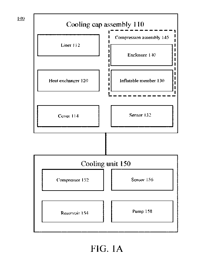
100511 FIG. lA is a block diagram of a variation of a cooling system (100)
comprising a
cooling cap assembly (110) and a cooling unit (150). The cooling cap assembly
(110) may be
configured to be removeably placed on a scalp of a patient and to decrease the
surface
temperature of a scalp during, for example, a chemotherapy treatment As shown
there, the
cooling cap assembly (110) may comprise a liner (112), a flexible heat
exchanger (120), and a
compression assembly (145), a cover (114), and one or more sensors (132). The
compression
assembly (145) may comprise an inflatable member (130) and an enclosure (140).
The heat
exchanger (120) may generally comprise fluid channels through which fluid may
circulate to
remove heat from a patient's scalp. The compression assembly (145) may be
configured to apply
a predetermined force to the heat exchanger to, for example, increase the
contact area between
the heat exchanger and a patient's scalp, which may increase the heat transfer
between the scalp
and the fluid circulating in the heat exchanger. For example, the enclosure
may provide a
counter force to the inflatable member when the inflatable member is in the
inflated
configuration.
100521 The cooling units described here may be fluidly coupled to the cooling
cap assemblies
described here to cool the cooling fluid and circulate the cooled fluid
through the heat
exchanger. For example, the cooling unit may comprise components to cool,
store, and pump
fluid (e.g., water, alcohol, glycol, a combination thereof) into and out of a
cooling cap assembly.
Turning back to FIG. 1A, as shown there, the cooling unit (150) may comprise a
compressor
(152), a reservoir (154), one or more sensors (156), and a pump (158). The
compressor (152)
may be configured to decrease the temperature of the cooling fluid and the
pump (158) may be
configured to circulate the cooling fluid through the cooling cap assembly
(110) (i.e., through
the heat exchanger). The one or more sensors (156) may be communicatively
coupled (e.g.,
wired or wirelessly) to a controller. As will be discussed in more detail
herein, the cooling unit
(150) may be fluidly coupled to the cooling cap assembly (110) by, for
example, a fluid conduit
or tubing assembly.
100531 Turning back to the cooling cap assembly (110), FIG. 1B is an exploded
perspective
view of a variation of the cooling cap assembly (110) configured to be placed
on the scalp of a
patient (101). The liner (112) may be placed on the scalp and the heat
exchanger (120) may be
placed over the liner (112) such that a bottom or inner surface of the heat
exchanger (120) may
be removeably coupled to the scalp through the liner (112). In some
variations, the cooling cap
11
CA 03139053 2021-11-22
WO 2020/247532
PCT/US2020/035971
assembly (110) may not include the liner (112), and the heat exchanger (120)
may be placed
directly on the scalp. The compression assembly (145) may be placed over the
heat exchanger
(120). More specifically, the inflatable member (130), which may be separate
from, and
moveable relative to, the heat exchanger (120), may be placed over the heat
exchanger (120)
(e.g., on top of the heat exchanger) such that a bottom or inner surface of
the inflatable member
(130) contacts a top or outer surface of the heat exchanger (120). As
mentioned above, the
enclosure (140) may be coupled to a top or outer surface of the inflatable
member (130), and
thus the enclosure (140) and the inflatable member (130) may be placed on the
user's head
simultaneously.
100541 In some variations, a cover (114) may be coupled to the enclosure (140)
(e.g., to an
outer surface of the enclosure (140)) and may be placed on the user's head
with the enclosure
(140) and the inflatable member (130). In other variations, the cover (114)
may be distinct from
the enclosure (140) and may be placed over the enclosure (140) and the user's
head separately.
The cover (114) may comprise a fastener, which may releasably attach the
cooling cap assembly
to the head of the patient (101). In some variations, the cooling cap assembly
may not include a
cover (114), and the enclosure (130) may comprise a releasable fastener to
couple to cooling cap
assembly to the head of the patient (101).
100551 When coupled, the inflatable member (130) may be positioned between the
enclosure
(140), which may comprise or otherwise serve as an outer shell, and the heat
exchanger (120).
The heat exchanger (120) may be separate from and moveable relative to the
inflatable member
(130). In some variations, the inflatable member (130) may comprise a pouch
having a top
surface and a bottom surface, and the bottom surface may be releasably coupled
to the heat
exchanger (120). The inflatable member may be coupled to a pump (not shown),
and the pump
may be configured inflate the pouch.. In some variations, the inflatable
member (130) may
comprise a plurality of chambers, as described in more detail herein, which
may be coupled to a
pump that may individually or simultaneously inflate the chambers. The
inflatable member (130)
may comprise a set of fluid conduits (144) (e.g., fluid pressure lines)
coupled to one or more
valves (142). For example, in variations comprising a plurality of fluid
conduits, each fluid
conduit may comprise or otherwise be fluidly coupled to a valve. The one or
more valves (142)
may be coupled to the pump (not shown).
12
CA 03139053 2021-11-22
WO 2020/247532
PCT/US2020/035971
100561 In some variations, transitioning the inflatable member (130) from a
deflated
configuration to an inflated configuration may increase a pressure applied to
the head of patient
by the cooling cap assembly and the contact area between the heat exchanger
(120) and the head
of the patient (101). In some variations, the compression assembly (145) may
be configured to
generate from about 0.1 lb/in2 to about 10 lb/in2 of compression to the head
when the inflatable
member (130) is in the inflated configuration. In some variations, the
compression assembly
(145) may be configured to generate from about 0.1 lb/in2 to about 8.0 lb/in2,
from about 0.1
lb/in2 to about 5.0 lb/in2, from about 0.1 lb/in2 to about 3M lb/in2, from
about 0.1 lb/in2 to about
2.0 lb/in2, from about 0.1 lb/in2 to about 1.0 lb/in2, from about 0.5 lb/in2
to about 8.0 lb/in2, from
about 0.5 lb/in2 to about 5.0 lb/in2, from about 0.5 lb/in2 to about 3.0
1b/in2, from about 0.5 lb/in2
to about 2.0 lb/in2, or from about 0.5 lb/in2 to about 1.0 lb/in2 of
compression to the head when
the inflatable member (130) is in the inflated configuration.
100571 In some variations, the cooling system may be a closed-loop system such
that one or
more parameters of one or more components of the cooling system (e.g., a pump
coupled to the
inflatable member, a pump circulating the cooling fluid, a compressor of a
cooling unit) may be
modified based on information received from one or more sensors. For example,
in some
variations, the heat exchanger (132) may comprise a plurality of temperature
sensors (132). The
plurality of temperature sensors (132) may be coupled (e.g., via wired or
wireless connection) to
a controller (140) (e.g., processor, memory). The controller may comprise
instructions and/or
execute instructions to receive a temperature from a temperature sensor and
adjust an output of
one or both of the pumps and/or the compressor based on the temperature. In
some variations,
the controller (140) may be configured to adjust or otherwise control a fluid
pressure of the
inflatable member (130) using the pump fluidly coupled thereto.
Heat Exchanger
100581 Generally, the heat exchangers described here may be configured to
remove heat from
a scalp of a patient via a cooling fluid circulating in one or more passages
therein. Due to the
shape of a patient's head and the geometry of a heat exchanger, a contact area
between the
patient's scalp and the heat exchanger may be inconsistent and/or suboptimal.
For example, the
weight and coverage area of the heat exchanger having circulating fluid may
not be sufficient to
provide the compression forces to evenly cool a patient's scalp, such as when
a patient moves
their head. In some variations, the contact area between the heat exchanger
and the scalp may be
13
CA 03139053 2021-11-22
WO 2020/247532
PCT/US2020/035971
increased using a compression assembly as described herein, which may improve
the
effectiveness of a cooling treatment. In some variations, the shape and
dimensions of the heat
exchanger may be configured to be adjustable such that the heat exchanger may
properly fit
patients having varying head shapes and sizes, which may also provide an
increased contact area
between the heat exchanger and the patient's head to increase effectiveness of
a cooling
treatment. In some variations, the heat exchanger may comprise a surface that
may be
comfortably placed directly on a scalp of a patient. For example, the interior
surface of the heat
exchanger may comprise a terry cloth surface.
100591 FIGS. 2A and 2B are schematic top and bottom (e.g., exterior and
interior) views
respectively of a variation of a heat exchanger (200). As shown there, the
heat exchanger (200)
may comprise a base portion (210), a top portion (221), a first side portion
(231), a second side
portion (241), and a fluid connector (270). The fluid connector (270) may be
used to couple the
heat exchanger (200) to a cooling unit and may be coupled to any suitable
portion of the heat
exchanger (200), for example, any of the base portion (210), the top portion
(221), or either side
portion (241). The fluid connector (270) may comprise a fluid conduit such as
tubing configured
to couple to an inlet and an outlet of a cooling unit. The top portion (221)
may be configured to
cover the top ridge and/or forefront of the head, the base portion (210) may
be configured to
cover the back of the head and/or the neck, and the first and second side
portions (231, 241) may
be configured to be cover the left and right hemispheres of the head. The base
portion (210) may
have a generally rectangular shape and may extend away from the top portion
(221).
[0060] In some variations, the top portion (221), the first side portion (231)
and/or the second
side portion (241) may comprise one or more arms or lobes, for example, two,
three, four, or
more. In some variations, the first side portion (231), the second side
portion (241), and the top
portion (221) may comprise only two lobes, and the heat exchanger (200) may
only comprise a
total of six lobes (i.e., the base portion (210) does not have any lobes). The
lobes of each portion
of the heat exchanger may be sized and shaped to adjustably cover different
portions of a
patient's head. For example, the lobes may generally be elongate (e.g., have a
larger length than
width) and may each have a curved or rounded distal end. One or more of the
distal ends may
comprise a fastener (e.g., hook, loop) used to fasten the lobes to each other.
Each lobe may
extend from the base (210) and may be flexible so as to allow conformance to a
patient's head
and for patient adjustment. In variations in which the top portion (221),
first side portion (231),
14
CA 03139053 2021-11-22
WO 2020/247532
PCT/US2020/035971
and second side portion (241) comprise a plurality of lobes, each lobe in each
portion may be the
same (e.g., have the same shape, length, width, surface area, and/or radius of
curvature of the
distal end) or each lobe may be different (e.g., have a different shape,
length, width, surface area,
and/or radius of curvature of the distal end). For example, in some
variations, each of the top
portion (221), first side portion (231), and second side portion (241) may
comprise two lobes,
the lobes (220, 222) in the top portion (221) may have the same length and
width as one another,
and the length and width of the lobes (220, 222) in the top portion (221) may
be different from
the length and width of the lobes (230, 232, 240, 242) in the side portions
(when length and
width of each lobe is measured relative to the proximal end of the heat
exchanger (200)). In
some instances, one or more lobes (230, 232) in the first side portion (231)
may be a mirror
image of one or more lobes (240, 242) in the second side portion (241) and/or
the lobes (220,
222) in the top portion (221) may be mirror images of one another.
[0061] As shown in FIG. 2A, for example, the top and side portions of the heat
exchanger
(200) may generally form a cactus-like shape or that of a set of splayed
fingers. In some
variations, the top portion (221) and base portion (210) may define a common
longitudinal axis.
The first side portion (231) and the second side portion (241) may extend from
the base portion
(210) at an acute angle with respect to the longitudinal axis. The lobes of
the side portions may
have different acute angles with respect to the longitudinal axis. In some
variations, one or more
of the lobes may be tapered. In some variations, the lobes may extend from
either another
portion of the heat exchanger (e.g., first lobe (230) extends from base
portion (210) at an acute
angle) or from another lobe (e.g., second lobe (232) extends from first lobe
(230)). In some
variations, a length of a first lobe to a length of a second lobe may be from
about 2:1 to about
0.5:1. In some variations, a width of a first lobe to a width of a second lobe
may be from about
2:1 to about 0.5:1.
[0062] In the variation depicted in FIGS. 2A-2B, the top portion (221) may
comprise a first
lobe (220) and a second lobe (222), the first side portion (231) may comprise
a first lobe (230)
and a second lobe (232), and the second side portion (241) may comprise a
first lobe (240) and a
second lobe (242). As shown there, the length of the first lobes (230, 240) of
the first portion
(231) and the second portion (241) may be greater than a length of the second
lobes (232, 242)
of the first portion (231) and the second portion (241). Additionally or
alternatively, the length
of the first and second lobes in the first side portion (231) and the second
side portion (241) may
CA 03139053 2021-11-22
WO 2020/247532
PCT/US2020/035971
be less than the length of the first and second lobes in the top portion
(221). In some variations,
an area of either the first side portion or the second side portion to an area
of the top portion is
from about 2:1 to about 0.5:1. In some variations, the heat exchanger (200)
may comprise a
length of from about 30 cm to about 50 cm, and a width of from about 35 cm to
about 80 cm.
100631 The heat exchanger (200) may generally comprise one or more fluid
channels (not
shown) forming a fluid path through at least one of the base portion (210),
the top portion (221),
the first side portion (231), and the second side portion (241). For example,
in some variations,
each portion of the heat exchanger (200) may comprise at least a portion of a
fluid channel. In
some instances, each portion of the heat exchanger (200) comprises a plurality
of fluid channels
(e.g., two, three, four, or more). The fluid channels may have any size and
shape suitable to
circulate cooling fluid through the portions of the heat exchange. For
example, each fluid
channel may comprise a cross-sectional area of from about 9 MM2 to about 100
mm2. When in
use, the fluid channels may comprise circulating fluid that may have a
temperature that is lower
than a temperature of the scalp of a patient. FIG. 2M illustrates one
variation of a fluid flow
pattern of a heat exchanger (200). In the variation shown there, each lobe of
the heat exchanger
(200) may comprise two fluid channels and fluid may enter (260) and exit (262)
the heat
exchanger (200) through a base portion of the heat exchanger (200).
100641 As shown in at least FIGS. 2A, 2B, and 2N, the heat exchanger (200) may
comprise
one or more releasable fasteners (280) (e.g., hooks, loops, Velcro , a
combination thereof or the
like) configured to form and hold the heat exchanger (200) in a predetermined
shape
configuration. For example, one or more end portions of the heat exchanger
(200) may comprise
fasteners having any suitable shape or size. FIGS. 2A and 2B show a set of
fasteners (280)
coupled to distal ends of the lobes. For example, a semispherical loop
fastener may be disposed
on a first side of the heat exchanger (200) (FIG. 2A) on a distal end of each
lobe. On a second
side of the heat exchanger (200) opposite the first side (FIG. 2B), a
semispherical hook fastener
may be disposed on four of the lobes. Furthermore, a loop fastener may be
disposed on the
second side of the base portion (210). The portions and/or lobes may be
manipulated such that
the hooks and loops of different portions may overlap and couple to each other
so as to wrap
around and secure the heat exchanger to a scalp of a patient.
100651 In some variations, the heat exchanger (200) may comprise a flexible
material such as
nylon, urethane coated nylon, woven polyester, polyvinyl chloride (PVC), loop
fabric, non-
16
CA 03139053 2021-11-22
WO 2020/247532
PCT/US2020/035971
woven fabric, combinations thereof and the like. This may allow one or more
portions of the
heat exchanger (200) to be manipulated and adjusted to conform to a shape of a
patient's head
and to accommodate patients of various head sizes. As shown in the side and
front schematic
views of FIGS. 2C and 2D, the heat exchanger (200) may be generally shaped to
be wrapped
around a head of a patient. For example, one or more end portions of the heat
exchanger may be
configured to adjustably overlap so as to surround at least a portion of the
head, as described
herein in more detail with respect to FIGS. 2H-2L.
100661 The heat exchanger (200) may be formed from several layers that may be
coupled to
one another, one or more of which may form fluid passageways within the heat
exchanger. FIG.
2G is a schematic cross-sectional view of a portion of one variation of the
layers of a heat
exchanger (200). The heat exchanger (200) may comprise a first, bottom layer
(250) configured
to face a patient and a second, top layer (254) configured to face away from
the patient (e.g.,
face an inflatable member). The first layer (250) and the second layer (254)
may form a cavity
and/or one or more of fluid channels (depicted schematically as 252)
therebetween, which may
receive circulating fluid when the heat exchanger is in use. In some
variations, the layers of the
heat exchanger may be radio frequency or thermally welded to one another to
form a circuitous
and/or tortuous path for circulating fluid and may be water impermeable. In
some variations, the
first layer (250) and/or the second layer (254) may comprise a flexible
material such as nylon. In
some variations, for example, when a liner is not used, the second layer (254)
may comprise a
soft fabric such as terry cloth and/or absorbent fabric. Additionally or
alternatively, in some
variations, one or more portions of the heat exchanger (200) (e.g., the first
layer (250) or a
portion thereof and/or the second layer (254) or a portion thereof) may
optionally comprise a
compressible material (e.g., an open cell foam, a closed cell foam). In
variations comprising a
compressible material, the compressible material may be integrated into or
embedded within one
or more layers of the heat exchanger and/or may be attached to an internal
and/or external
surface of one or more layers of the heat exchanger (200). Utilizing a
compressible material may
increase the rigidity of the heat exchanger (200) so as to increase resistance
to buckling from, for
example, internal liquid pressure and/or may increase a distance between the
first layer (250) of
the heat exchanger (200) and the patient's scalp, which may reduce the risk of
frostbite. FIGS.
2E and 2F are schematic side cross-sectional views of the heat exchanger
(200). For example,
FIG. 2E illustrates the first layer (250) comprising a hook fastener (260) and
the second layer
(254) comprising a hook fastener (260) and loop fastener (262).
17
CA 03139053 2021-11-22
WO 2020/247532
PCT/US2020/035971
[0067] FIGS. 11A and 1111 are schematic views of additional variations of a
heat exchanger
(1100) comprising a design configured for efficient cooling and fluid flow. As
shown there, the
heat exchanger (1100) may comprise a base portion (1110), a top portion
(1121), a first side
portion (1131) comprising a first arm (1130), a second side portion (1141)
comprising a second
arm (1140)), and a fluid connector (1170). Furthermore, one or more portions
of the heat
exchanger (1100) may comprise one or more fluid barriers (1150, 1152, 1154,
1156) (e.g., a
plurality of fluid bathers such as two, three, four, five, or more), one or
more fasteners (1180),
(e.g., a plurality of fasteners such as two, three, four, five or more), and
one or more sensors
(1182) (e.g., a plurality of sensors such as two, three, four, five or more).
The fluid connector
(1170) may be configured to couple the heat exchanger (1100) to a cooling unit
(not shown) and
may be coupled to any suitable portion of the heat exchanger (1100), for
example, any of the
base portion (1110), the top portion (1121), or either side portion (1131,
1141). The fluid
connector (1170) may comprise a fluid conduit such as tubing configured to
couple to an inlet
and an outlet of a cooling unit. The top portion (1121) may be configured to
cover the top ridge
and/or forefront of the head, the base portion (1110) may be configured to
cover the back of the
head and/or the neck, and the first and second side portions (1131, 1141) may
be configured to
cover the left and right hemispheres of the head. For example, the top portion
(1121) may have a
generally circular or ellipsoidal shape, the first and second side portions
(1131, 1141) may have
a generally elongate shape with rounded (e.g., bulbous) ends and the base
portion (1110) may
have a generally tapered shape and may extend away from the top portion (1121)
and side
portions (1131, 1141).
[0068] In some variations, the top portion (1121), the first side portion
(1131) and/or the
second side portion (1141) may each comprise one or more arms or lobes, for
example, one,
two, three, four, or more. In some variations, the first side portion (1131),
the second side
portion (1141), and the top portion (1121) may comprise three arms or lobes in
total, and the
heat exchanger (1100) may only comprise a total of three arms or lobes (i.e.,
the base portion
(1110) may not have any arms). The arms of each portion of the heat exchanger
may be sized
and shaped to adjustably cover different portions of a patient's head. For
example, the arms of
each of the first and second side portions may generally be elongate (e.g.,
have a larger length
than width) and may each have a curved or rounded distal end. The top portion
(1121) may have
a generally circular or ellipsoidal shape in the shape of a head. One or more
of the distal ends
may comprise a fastener (e.g., hook, loop) used to fasten the arms to one
another. Each arm may
18
CA 03139053 2021-11-22
WO 2020/247532
PCT/US2020/035971
extend outward from the base (1110) in opposing directions and may be flexible
so as to allow
conformance to a patient's head and for patient adjustment. In variations in
which the top
portion (1121), first side portion (1131), and second side portion (1141) each
comprise a
plurality of arms, each arm in each portion may be the same (e.g., have the
same shape, length,
width, surface area, and/or radius of curvature of the distal end) or each arm
may be different
(e.g., have a different shape, length, width, surface area, and/or radius of
curvature of the distal
end).
100691 As shown in FIGS. 11A-11C, for example, the top and side portions of
the heat
exchanger (1100) may generally form one or more of a humanoid shape (e.g.
scarecrow), T-
shape, and/or cross shape. In some variations, the top portion (1121) and base
portion (1110)
may define a common longitudinal axis, and in some instances, the fluid
barrier (1152) may
generally extend along the common longitudinal axis (e.g., the fluid barrier
(1152) may
generally extend along a longitudinal axis of the heat exchanger (1100)). The
first side portion
(1131) and the second side portion (1141) may extend from the base portion
(1110) at an acute
angle with respect to the longitudinal axis. In some variations, the first
side portion (1131) and
the second side portion (1141) may form a generally curved shape relative to
the base portion
(1110). For example, the side portions may extend from the base portion (1110)
at the same or at
different arcuate angles with respect to the longitudinal axis. In some
variations, one or more of
the arms may be tapered (e.g., proximal end has a larger width than distal
end, distal end has a
larger width than a proximal end). In some variations, the arms may extend
from either another
portion of the heat exchanger (e.g., first arm (1130) extends from base
portion (1110) at an acute
angle) or from another arm (e.g., second arm (1132) extends from top portion
(1121)). For
example, the first arm (1130) and the second arm (1132) may form an angle from
about zero
degrees to about 80 degrees relative to the longitudinal axis. In some
variations, a ratio of the
length of a first arm to the length of a second arm may be from about 2:1 to
about 0.5:1. In some
variations, a ratio of the width of a first arm to the width of a second arm
may be from about 2:1
to about 0.5:1.
[0070] In some variations, the heat exchanger (1100) may comprise a length of
from about 30
cm to about 50 cm, including all sub-ranges and values in-between, for
example, from about 35
cm to about 45 cm. In some variations, the heat exchanger (1100) may comprise
a width of from
about 35 cm to about 80 cm, including all sub-ranges and values in-between. In
some variations,
19
CA 03139053 2021-11-22
WO 2020/247532
PCT/US2020/035971
a ratio of a length of an arm to a diameter of the top portion may be from
about 3:2 to about 3'4.
For example, in some variations, the top portion (1121) may comprise a
diameter of about 20
cm, and the base portion (1110) may comprise a length of about 20 cm, and each
side portion
(1131, 1141) may comprise a length of about 25 cm.
100711 The heat exchanger (1100) may generally comprise a fluid path (e.g.,
fluid channels)
through at least one of the base portion (1110), the top portion (1121), the
first side portion
(1131), and the second side portion (1141). For example, in some variations,
each portion of the
heat exchanger (1100) may comprise at least a portion of a fluid path. The
fluid path may have
any size and shape suitable to circulate cooling fluid through the portions of
the heat exchanger
(1100). When in use, the fluid path may comprise circulating fluid that may
have a temperature
that is lower than a temperature of the scalp of a patient. FIGS. 11A and 11B
illustrate variations
of a fluid flow pattern (1190, 1192) of a heat exchanger (1100). In the
variations shown there,
fluid may enter (1190) and exit (1192) the heat exchanger (1100) through the
base portion
(1110) (e.g., at a proximal end of the base portion (1110)) of the heat
exchanger (1100). For
example, fluid may flow in a generally counter-clockwise direction
sequentially through the base
portion (1110), second side portion (1141), top portion (1120), first side
portion (1131), and out
through the base portion (1110).
100721 In some variations, a heat exchanger (1100) may comprise a fluid bather
configured to
direct fluid flow through the heat exchanger (1100) and to provide a
predetermined shape to the
heat exchanger (1100) in an expanded configuration. The fluid barriers
described herein may aid
in promoting even and consistent cooling and may reduce pooling of fluid
within the heat
exchanger (1100). For example, the fluid bathers may be configured to reduce
turbulent fluid
flow throughout the heat exchanger (1100) by defining a predetermined fluid
flow path.
Furthermore, the fluid barriers may be configured to reduce expansion of one
or more portions
of a heat exchanger (1100). In some variations, the heat exchanger (1100) may
comprise a set of
fluid barriers (1150, 1152, 1154, 1156) including, but not limited to, point
fluid bathers,
elongate fluid barriers, rounded fluid barriers, and shaped fluid barriers.
For example, the fluid
barriers may include one or more of a sidewall and weld within an interior
cavity of the heat
exchanger (1100) which does not include the walls defining the outer perimeter
(e.g., boundary)
of the heat exchanger (1100). For example, each barrier may be coupled between
opposing
layers (e.g., top layer, bottom layer) of the heat exchanger (1100) such that
when the heat
CA 03139053 2021-11-22
WO 2020/247532
PCT/US2020/035971
exchanger (1100) is in an expanded configuration (e.g., filled with fluid),
the heat exchanger
(1100) may maintain a predefined thickness and shape throughout rather than
"ballooning" out.
As described in more detail herein, one or more of the fluid barriers may be
formed by a welding
process.
100731 In some variations, an elongate fluid barrier (1152, 1153, 1155) may
define a fluid flow
path through one or more portions and/or arms of the heat exchanger (1100) and
may provide a
predetermined shape to the heat exchanger (1100). For example, FIG. 11A
illustrates that a
longitudinal elongate fluid bather (1152) may bisect each of the base portion
(1110) and the top
portion (1121). Similarly, lateral elongate fluid bathers (1153, 1155) may
bisect the first side
portion (1131) and the second side portion (1141), and the top portion (1121),
respectively. In
FIG. 11A, the longitudinal elongate fluid bather (1152) may form a cross-like
shape with each
of the lateral elongate fluid bathers (1153, 1155) so as to form a circuitous
fluid path through the
heat exchanger (1100). One or more elongate fluid barriers (1154) shorter than
the longitudinal
or lateral elongate fluid barriers (1152) may be disposed in close proximity
to the intersections
formed between the lateral and longitudinal elongate fluid bathers (1152,
1153, 1155) in order
to reduce fluid back pressure (e.g., pooling) in those regions. The elongate
fluid barriers (1154)
may be generally parallel or angled relative to the lateral or longitudinal
elongate fluid bathers
(1154).
100741 FIG. 11B illustrates curved elongate fluid bathers (1162) configured to
promote non-
turbulent or laminar fluid flow near, for example, intersections ancUor curved
portions of the heat
exchanger (1100). FIG. 11C is an image of the heat exchanger (1100) depicted
schematically in
FIG. 11B. The elongate fluid bathers (1162, 1164) depicted in FIGS. 11B and
11C may
comprise one or more curves to reduce fluid back pressure and turbulent flow.
Elongate fluid
bathers may form a circuitous fluid path through the heat exchanger (1100).
For example, FIG.
11B illustrates that a first elongate fluid bather (1162) that extends through
the base portion
(1110) and the second side portion (1141). A second elongate fluid bather
(1164) extends
through the first side portion (1131) and the top portion (1120). The first
and second elongate
fluid bathers (1162, 1164) may be coupled by third elongate fluid bather
(1166). A lateral
elongate fluid bather (1165) may form a cross-like shape with respect to the
second elongate
fluid bather (1164). One or more elongate fluid bathers (1154) shorter than
the first and second
elongate fluid bathers (1162 ,1164) may be disposed in close proximity to the
intersections
21
CA 03139053 2021-11-22
WO 2020/247532
PCT/US2020/035971
formed between the first, second, third, and lateral elongate fluid barriers
(1162, 1164, 1165,
1166) in order to reduce fluid back pressure (e.g., pooling) in those regions.
The elongate fluid
barriers (1154) may be generally parallel or angled relative to the elongate
fluid bathers (1162,
1164, 1165, 1166).
100751 In some variations, the set of fluid bathers may comprise a fluid
bather pattern of
spaced-apart fluid barriers (1150) configured to define a fluid flow path and
provide a
predetermined shape to the heat exchanger (1100). For example, FIGS. 11A and
11B illustrate a
set of fluid barriers (1150) comprising a torus-like (e.g., donut, dot,
cylinder) shape that may be
distributed generally evenly throughout a cavity of the heat exchanger (1100).
The center (e.g.,
hole) of the torus-like fluid bathers are not in fluid communication with the
fluid in the heat
exchanger. In some variations, one or more of the torus-like fluid bathers
(1150) may comprise
a diameter of from about 5 min to about 10 min and may be spaced apart from
other fluid
barriers (1150) from about 5 mm to about 15 mm. For example, in some
variations, one or more
(e.g., a plurality, all) of the torus-like fluid bathers (1150) may comprise a
diameter of about 7
mm, and the spacing between the torus-like fluid barriers may be at least 10
mm (e.g., about 10
mm). In some variations, the set of tori (1150) may be generally evenly spaced
apart. Each fluid
barrier of the set of fluid barriers (1150) may have the same or different
diameters. Additionally
or alternatively, the set of fluid barriers (1150) may comprise other shapes
such as a hemisphere,
rectangle, triangle, rhomboid, trapezoid, and other polygon, or a combination
thereof (e.g., a
plurality of fluid bathers may comprise a first shape (e.g., a torus-like
shape) and a plurality of
fluid barriers may comprise a second, different shape (e.g., a solid circular
shape).
100761 In some variations, one or more (e.g., a plurality, two, three, four,
or more) fluid
bathers (e.g., fluid barrier (1154)) may comprise a barbell or dumbbell-like
shape having a
torus-like or circular fluid barrier (or point barriers) coupled to each end
of an elongate fluid
barrier. These fluid bathers (1154) may be configured to direct fluid flow in
a predetermined
manner. For example, the elongate fluid bathers (1152, 1154) may promote
laminar fluid flow
near intersections and sharp angles to reduce fluid back pressure (e.g.,
pooling, dead spots).
Fluid that is relatively stagnant within the heat exchanger (1100) may
comprise a relatively
higher temperature that may reduce one or more of efficiency and performance
of the cooling
cap assembly. Thus, elongate fluid barriers may enable non-turbulent flow
throughout the heat
exchanger (1100). In some variations, the elongate fluid bather (1152, 1153,
1154, 1162, 1164,
22
CA 03139053 2021-11-22
WO 2020/247532
PCT/US2020/035971
1165, 1166) may be linear or curved, and may comprise a width equal to or less
than a diameter
or width of the fluid barrier ends (e.g., torus-like fluid barrier, point
barrier).
[0077] As described in more detail herein, in some variations, the heat
exchanger (1100) may
comprise one or more sensors (1182), such as, for example, one or more sensors
configured to
measure temperature. For example, a sensor (1182) may be disposed within the
inner "donut
hole" (e.g., through hole) of the torus-like fluid bathers (1150) at one or
more (e.g., two, three,
four, or more) predetermined locations within the heat exchanger (1100), as
indicated in FIG.
118, In some variations, a notification may be generated when one or more
measured
temperatures is outside a predetermined temperature range or other criteria.
For example, in
some variations, a patient may be notified if a temperature at one sensor
differs from one or
more other sensors by a predetermined amount (e.g., 2 C or more temperature
differential).
[0078] Additionally, in some variations, the heat exchanger (1100) may
comprise one or more
releasable fasteners (1180) (e.g., hooks, loops, Velcro , a combination
thereof or the like)
configured to form and hold the heat exchanger (1100) in a predetermined shape
configuration.
For example, one or more end portions of the heat exchanger (1100) may
comprise fasteners
(1180) having any suitable shape or size. FIGS. 11A and 11B show a set of
fasteners (1180)
coupled to distal ends of the arms. For example, a semispherical loop fastener
may be disposed
on a first side of the heat exchanger (1100) on a distal end of each arm. On a
second side of the
heat exchanger (1100) opposite the first side, a semispherical hook fastener
may be disposed on
a set of the arms. Furthermore, a loop fastener may be disposed on the second
side of the base
portion (1110). In some variations, the fasteners (1180) of the top portion
(1120) may comprise a
triangular shape to allow the top portion (1120) to form a concave or "bowl"
shape when the
heat exchanger (1100) is in the expanded configuration. For example, FIGS. 11A-
11C depict a
set of four triangular shaped fasteners (e.g., Velcro ) and three tab-shaped
fasteners on a top
portion (1120) of the heat exchanger (1100).
[0079] In some variations, the portions and/or arms may be manipulated such
that the hooks
and loops of different portions may overlap and couple to each other so as to
wrap around and
secure the heat exchanger to a scalp of a patient. For example, the fasteners
(1180) on the distal
ends of the side portions (1130, 1140) may be wrapped around the side of the
patient's head to
meet (e.g., couple, overlap) over a patient's forehead. Then, the tab-shaped
fasteners (1180)
23
CA 03139053 2021-11-22
WO 2020/247532
PCT/US2020/035971
protruding from the top portion (1120) may be coupled to the fasteners (1180)
of the side
portions (1131, 1141) to secure the top portion (1120) to the side portions
(1131, 1141),
[0080] In some variations, the heat exchanger (1100) may comprise a flexible
material such as
nylon, urethane coated nylon, woven polyester, polyvinyl chloride (PVC), loop
fabric, non-
woven fabric, combinations thereof and the like. This may allow one or more
portions of the
heat exchanger (1100) to be manipulated and adjusted (e.g., wrapped) to
conform to a shape of a
patient's head and to accommodate patients of various head sizes.
[0081] In some variations, the heat exchanger (1100) may be formed from
several layers that
may be coupled to one another, one or more of which may form one or more fluid
passageways
(e.g., fluid paths) within the heat exchanger. For example, the heat exchanger
(1100) may
comprise a first layer configured to face a patient and a second layer
configured to face away
from the patient (e.g., face an inflatable member). In some variations, the
layers of the heat
exchanger may be radio frequency or thermally welded to one another to form a
circuitous fluid
path for circulating fluid and may be water impermeable. For example,
radiofrequency welding
may comprise passing electricity using a manufacturing device through the
portion of the heat
exchanger to be welded. Localized heat and pressure applied by the
manufacturing device may
create a strong weld (e.g., bond). In some variations, the heat exchanger
(1100) may comprise a
fabric laminated with thermoplastic polyurethane (TPU).
[0082] In some variations, the heat exchanger (1100) may comprise a flexible
material such as
nylon and/or non-woven fabric. Additionally or alternatively, in some
variations, one or more
portions of the heat exchanger (1100) may optionally comprise a compressible
material (e.g,, an
open cell foam, a closed cell foam). In variations comprising a compressible
material, the
compressible material may be integrated into or embedded within one or more
layers of the heat
exchanger and/or may be attached to an internal and/or external surface of one
or more layers of
the heat exchanger (1100) which may increase resistance to buckling from, for
example, internal
liquid pressure and/or reduce the risk of frostbite.
Compression Assembly
[0083] The compression assemblies described herein may be configured to
increase a contact
area between a heat exchanger and a scalp of a patient (in some variations,
the contact may be
24
CA 03139053 2021-11-22
WO 2020/247532
PCT/US2020/035971
through a liner), which may increase the cooling efficiency of the cooling cap
assembly. The
compression assemblies described here may generally comprise an inflatable
member and an
enclosure, and may be separate from and moveable relative to the heat
exchanger. Put another
way, the compression assembly may be formed separately from the heat exchanger
and may be
removed or otherwise physically separated from the heat exchanger, for
example, during
application of the heat exchanger to a patient's scalp. When in use, an
interior surface of the
inflatable member may contact the heat exchanger and an exterior surface of
the inflatable
member may contact the enclosure. As the inflatable member is inflated, the
enclosure may be
configured to resist deformation from the inflatable member and provide a
counter force such
that the compression assembly may apply a compressive force to the heat
exchanger. This
compressive force may increase a contact area between the heat exchanger and
the scalp, by for
example, pressing the heat exchanger into a patient's scalp such that the heat
exchanger better
conforms to the shape of the patient's scalp. For example, the contour and
shape of a patient's
scalp may be such that the arms or lobes of a heat exchanger may not fully
contact all or a
substantial portion of the scalp unless pressure is applied to push the arms
or lobes towards the
scalp. This application of pressure may allow any voids, gaps, divots, etc.
between the heat
exchanger and the scalp to be reduced. In some variations, the compression
assembly may
comprise one or more sensors.
Inflatable Member
[0084] The inflatable members described here may be configured to receive a
fluid to
transition from a deflated configuration to an inflated configuration in order
to increase a force
applied by the heat exchanger to the head of a patient. FIGS. 3A and 3B are
plan views of a
variation of an inflatable member (300). The inflatable member (300) may
comprise a base
inflatable portion (310), a top inflatable portion (320, 322), a first
inflatable side portion (330,
332), and a second inflatable side portion (340, 342). The base inflatable
portion (310) may be
aligned with the neck and/or rear head of the patient with the top inflatable
portion (321) laid
over the top ridge and/or forefront of the head. When placed on a patient's
head, the side
portions (331, 341) may drape over the left and right hemispheres of the head.
Each portion may
comprise at least one chamber configured to be filled with a fluid (e.g.,
liquid, gas (e.g., air)).
For example, the inflatable member may comprise a plurality of chambers (e.g.,
two, three, four,
five, or more). For example, in one variation, the inflatable member may
comprise a front central
CA 03139053 2021-11-22
WO 2020/247532
PCT/US2020/035971
chamber, a front left chamber, a front right chamber, a top chamber, a back
central chamber, a
back right chamber, and a back right chamber. In some variations, each of the
plurality of
chambers may be independently inflatable. As mentioned above, the inflatable
member (300)
may comprise a deflated configuration and an inflated configuration. When in
use on the head of
a patient, transitioning the inflatable member (300) from the deflated to the
inflated
configuration may increase a pressure applied to the head of the patient.
100851 In some variations, a length of the first inflatable side portion (330,
332) and the
second inflatable side portion (340, 341) may be less than a length of the top
inflatable portion
(320, 322). Similar to the heat exchangers described herein, portions of the
inflatable member
(300) may be configured to adjustably overlap so as to surround at least a
portion of the head.
For example, FIGS. 3B and 3D are top and perspective views of variations of an
inflatable
member (300) held in an enclosure (360). The side and top portions of the
inflatable member
(300) may overlap one another so as to form a generally hemi-spherical shape.
In some
variations, the inflatable member (300) may be removeably coupled to the
enclosure (360). In
other variations, the inflatable member (300) may be fixed to the enclosure
(360).
100861 The inflatable member (300) may comprise one or more fluid connectors
(e.g., tubing)
coupled to one or more of the inflation portions (310, 321, 331, 341). In some
variations, the
inflatable member (300) may further comprise a manual pump fluidly coupled to
the one or
more chambers of the inflatable member (300) via the fluid connector(s). In
other variations, the
inflatable member may be fluidly coupled to a separate pump, for example, an
air pump
contained in the cooling unit, via the one or more fluid connectors. In some
variations, one or
more of the fluid conduits may comprise a valve that may be used to control or
assist in
controlling the inflation pressure.
100871 FIG. 3C depicts a variation of an inflatable member 300 comprising a
fluid pump (e.g.,
air bulb) (350). The fluid pump (350), shown there as manual hand pump (e.g.,
an air pump
bulb), may be coupled to a fluid connector (354) via flexible tubing (352).
The flexible tubing
(352) may fluidly couple the one or more chambers in the inflation portions
(310, 321, 331, 341)
to the fluid pump (350) such that the fluid pump (350) may be actuated to fill
one or more
chambers of the inflatable member (300) to a predetermined pressure (inflation
pressure) with,
for example, air and/or an inert gas. In some variations, the fluid pump (350)
may be actuated by
the patient, which may allow the patient to adjust the force applied by the
compression assembly
26
CA 03139053 2021-11-22
WO 2020/247532
PCT/US2020/035971
to the patient's head via the heat exchanger. This may allow for increased
adjustability and
comfort of the cooling cap assembly, and may allow for a degree of contact
between the heat
exchanger and the scalp. As mentioned above, in some variations, the cooling
unit may comprise
the fluid pump (350). In these variations, the cooling system may further
comprise a controller
that may be configured to manually (e.g., via user input) and/or dynamically
(e.g., using sensor
data) control an inflation pressure of the inflatable member (300) using the
fluid pump (350).
100881 In some variations, an inflatable member may be configured to conform
to the shape of
a patient's head when inflated and held in an enclosure such as a cooling cap.
FIG. 12A is a
schematic view of another variation of an inflatable member (1200). FIG. 12B
is a bottom view
of a variation of an inflatable member (1200) in a first configuration (e.g.,
uninflated
configuration) when held in an enclosure. FIG. 12C is a bottom view of an
illustrative variation
of an inflatable member in a second configuration (e.g., inflated
configuration) when held in an
enclosure. Similarly, FIG. 12D is an image of illustrative variations of an
inflatable member in
respective first and second configurations.
100891 The inflatable member (1200) depicted in FIGS. 12A-12D may comprise a
base
inflatable portion (1210), a top inflatable portion (1220) (e.g., top chamber
(1221)), a first
inflatable side portion (1230) (e.g., left chamber (1231)), and a second
inflatable side portion
(1240) (e.g., right chamber (1241)), fluid barriers (1250), fluid connector
(1270), slits or voids
(1242), and fasteners (1280). The base inflatable portion (1210) may be
aligned with the neck
and/or rear head of the patient with the top inflatable portion (1221) laid
over the top ridge
and/or forefront of the head. When placed on a patient's head, the inflatable
side portions (1230,
1240) may cover over the left and right hemispheres of the head. Each portion
may comprise at
least one chamber configured to be filled with a fluid (e.g., liquid, gas such
as air). For example,
the inflatable member (1200) may comprise a plurality of chambers (e.g., two,
three, four, five,
or more). For example, in one variation, the inflatable member (1200) may
comprise a left
chamber (1231), a right chamber (1241), and a top chamber (1221). As mentioned
above, the
inflatable member (1200) may comprise a first deflated configuration, a second
inflated
configuration, and a plurality of partially-inflated configurations in-
between. When in use on the
head of a patient, transitioning the inflatable member (1200) from the first
deflated configuration
to the second inflated configuration may increase a pressure applied to a heat
exchanger and the
head of the patient.
27
CA 03139053 2021-11-22
WO 2020/247532
PCT/US2020/035971
[0090] In some variations, the top portion (1220) may have a generally
ellipsoidal or circular
shape. The first and second side portions (1230, 1240) (e.g., wings, arms) may
have a generally
elongate shape that may be concave to form a "bowl" shape The base portion
(1210) may have
a generally tapered shape and may extend away from the top portion (1220). In
some variations,
a length of the first inflatable side portion (1230) and the second inflatable
side portion (1240)
(along a respective longitudinal axis) may be more than a length of the top
inflatable portion
(1220) (along a longitudinal axis of the top inflatable portion). Similarly to
the heat exchangers
described herein, portions of the inflatable member (1200) may be configured
to adjustably
overlap so as to surround at least a portion of the head. For example, FIGS.
12B and 12C are top
views of variations of an inflatable member (1200) held in an enclosure
(1260). The side
portions (1230, 1240) and top portion (1220) of the inflatable member (1200)
may overlap one
another so as to form a generally hemi-spherical shape. In some variations,
the inflatable
member (1200) may be removeably coupled to the enclosure (1260). In other
variations, the
inflatable member (1200) may be fixed to the enclosure (1260). When held in
the enclosure
(1260) in the inflated configuration, the inflatable member (1260) may be
configured to apply a
generally even amount of pressure to the head of a patient. In some
variations, the inflatable
member (1200) may comprise one or more slits (1242), voids, or indents to aid
in the folding,
shaping, and/or overlapping of different portions of the inflatable member
(1200) within an
enclosure (1260).
[0091] In some variations, the top portion (1220) and base portion (1210) may
define a
common longitudinal axis that bisects the inflatable member (1200). The first
side portion
(1230) and the second side portion (1240) may extend from the base portion
(1210) at an acute
angle with respect to the longitudinal axis. For example, the first side
portion (1230) and the
second side portion (1240) may form an angle from about zero degrees to about
80 degrees
relative to the longitudinal axis. In some variations, the ratio of a length
of a first portion to a
length of a second portion may be from about 2:1 to about 0.5:1. For example,
the first portion
and the second portion may be mirror images of one another. In some
variations, a ratio of the
width of a first portion to the width of a second portion may be from about
2:1 to about 0.5:1.
[0092] In some variations, the inflatable member (1200) may comprise a length
from about 25
cm to about 50 cm, including all sub-ranges and values in-between, such as,
for example, from
about 30 cm to about 40 cm. In some variations, the heat exchanger (1200) may
comprise a
28
CA 03139053 2021-11-22
WO 2020/247532
PCT/US2020/035971
width of from about 35 cm to about 80 cm, from about 50 cm to about 70 cm,
from about 60 cm
to about 70 cm, including all sub-ranges and values in-between.
[0093] In some variations, one or more portions of the inflatable member
(1200) may
comprise one or more fluid bathers (1250). In some variations, the inflatable
member (1200)
may comprise a set of fluid barriers (1210) (e.g., walls, welds) configured to
provide a
predetermined shape to the inflatable member (1200) in an inflated
configuration. The fluid
barriers described herein may aid in promoting even and consistent inflation
of the inflatable
member (1200). For example, the fluid barriers may be configured to reduce
expansion of one or
more portions of an inflatable member (1200). Each bather may be coupled
between opposing
layers (e.g., top layer, bottom layer) of the inflatable member (1200) such
that when the
inflatable member (1200) is in an inflated configuration (e.g., filled with
fluid), the inflatable
member (1200) may maintain a predefined thickness and shape throughout rather
than
"ballooning" out. This may aid patient comfort and increase coding efficiency.
One or more of
the fluid barriers may be formed by a welding process a described herein. In
some variations,
one or more of the fluid bathers (1250) may be elongate and may generally
extend through a
mid-point of a chamber. That is, the fluid barriers (1250) may be disposed
within an interior
cavity of the inflatable member. For example, a fluid bather (1250) may be
linear and/or form a
"V"-like shape.
[0094] In some variations, one or more portions of the inflatable member
(1200) may
comprise one or more releasable fasteners (1280) (e.g., hooks, loops, Velcro ,
a combination
thereof or the like) configured to form and hold the inflatable member (1200)
in a predetermined
shape configuration. The inflatable member (1200) may be manipulated such that
the hooks and
loops of different portions may overlap and couple to each other so as to wrap
around and secure
the inflatable member within an enclosure. One or more edges of the inflatable
member (1200)
may comprise a fastener (e.g., hook, loop) used to fasten the portions to each
other. Each side
portion may extend from the base portion (1210) and may be flexible so as to
allow
conformance to a patient's head and for patient adjustment.
[0095] A fluid connector (1270) may be used to couple the inflatable member
(1200) to a
pump (not shown) and may be coupled to any suitable portion of the inflatable
member (1200),
for example, any of the base portion (1210), the top portion (1220), or either
side portion (1230,
1240). The fluid connector (1270) may comprise a fluid conduit such as tubing
configured to
29
CA 03139053 2021-11-22
WO 2020/247532
PCT/US2020/035971
couple to a pump. In some variations, the inflatable member (1200) may further
comprise a
manual pump fluidly coupled to the one or more chambers of the inflatable
member (1200) via
the fluid connector(s). In other variations, the inflatable member may be
fluidly coupled to an air
pump contained in the cooling unit, via the one or more fluid connectors. In
some variations, one
or more of the fluid conduits may comprise a valve that may be used to control
or assist in
controlling the inflation pressure.
100961 In some variations, one or more chambers of the inflatable member
(1200) may be
inflated to a predetermined pressure (inflation pressure) with, for example,
air and/or an inert
gas. In some variations, A fluid pump may be actuated by the patient, which
may allow the
patient to adjust the force applied by the compression assembly to the
patient's head via the heat
exchanger. This may allow for increased adjustability and comfort of the
cooling cap assembly,
and may allow for a degree of contact between the heat exchanger and the
scalp. As mentioned
above, in some variations, the cooling unit may comprise the fluid pump. In
these variations, the
cooling system may further comprise a controller that may be configured to
manually (e.g., via
user input) and/or dynamically (e.g., using sensor data) control an inflation
pressure of the
inflatable member (1200) using the fluid pump (1250).
100971 In some variations, the inflatable member (1200) may comprise a
flexible material such
as nylon, urethane coated nylon, woven polyester, polyvinyl chloride (PVC),
loop fabric, non-
woven fabric, combinations thereof and the like. This may allow one or more
portions of the
inflatable member (1200) to be manipulated and adjusted (e.g., wrapped) to
conform to a shape
of a patient's head and to accommodate patients of various head sizes. In some
variations, the
inflatable member (1200) may comprise a flexible material such as nylon and/or
non-woven
fabric.
100981 In some variations, one or more inflation portions and/or chambers of
the inflatable
member may be independently inflated and/or deflated. As shown in FIG. 1B, for
example, the
inflatable member may comprise a plurality of segmented chambers that may be
independently
inflated and/or deflated. In these variations, a fluid conduit (144) may be
coupled to each
chamber of the inflatable member (130) to allow independent control of the
fluid pressure in
each inflatable portion and/or chamber of the inflatable member. This may
allow for more
uniform cooling of the head by allowing for individual adjustment of the
inflation pressure of
each inflation portion and/or chamber as necessary. For example, after an
initial inflation of each
CA 03139053 2021-11-22
WO 2020/247532
PCT/US2020/035971
chamber to a predetermined inflation pressure, temperature sensors coupled to
each arm or lobe
of the heat exchanger may measure temperature readings that indicate uneven
cooling of the
scalp. In response, a controller may increase inflation pressure of chambers
corresponding to
arms or lobes having increased temperature by, for example, increasing an
output of the pump
fluidly coupled to those chambers or otherwise directing additional fluid into
those particular
chambers.
Enclosure
100991 Generally, the enclosures described here may comprise a surface
configured to resist
deformation as the inflatable member is moved from the deflated to the
inflated configuration.
The enclosures described here may provide a counter force to the inflatable
member as it is
inflated, which, when in use with a heat exchanger, may allow a compressive
force to be applied
by the heat exchanger to a patient's head. Using the enclosure as a counter
force to the inflatable
member in the inflated configuration may allow the inflatable member to retain
a uniform shape
when in the inflated configuration and may increase a contact area between the
heat exchanger
and a scalp of a patient.
101001 FIG. 13 is a perspective view of an illustrative variation of an
enclosure (1300)
comprising a shell (1310), strap (1312), chin strap (1314), strap fastener
(1316), shell fastener
(1318), inflatable member (1320), and inflatable member fastener (1322). In
some variations, the
shell (1310) may comprise a hemispherical or dome shape, and may be in the
form of a helmet.
For example, the shell (1310) may comprise a rigid (e.g., molded plastic) or a
semi-rigid
material. For example, the shell (1310) may be more rigid than the inflatable
member (1320). As
shown in FIG. 13, the shell (1310) may be configured to surround at least a
portion of, and in
some variations, the entire inflatable member (1320). For example, the shell
(1310) may define a
cavity configured to surround at least a portion of the inflatable member
(1320) and/or receive
the head of a patient (not shown). In some variations, the shell (1310) may be
surrounded by a
flexible cover as described herein. The shell (1310) may comprise one or more
ports (not shown)
configured to permit one or more fluid connectors to connect to one or more of
the inflatable
member (1320) and a heat exchanger (not shown). The ports may be further
configured to permit
wired connection to one or more sensors of the cooling cap assembly. In some
variations, the
shell (1310) may comprise one or more electronic components (e.g., processor,
memory, PCB,
battery, leads, audio output device, haptic feedback device, visual output
device) of the cooling
31
CA 03139053 2021-11-22
WO 2020/247532
PCT/US2020/035971
cap assembly._ For example, the shell (1310) may comprise an audio output
device near an
earhole portion of the enclosure (1300) configured to provide audio
notification related to a
cooling treatment (e.g., operation state) of the cooling cap assembly. As
another example, a
haptic feedback device may be configured to vibrate during a power state
transition of a cooling
unit coupled to the cooling cap.
101011 In some variations, the enclosure (1300) may comprise one or more
straps (1312)
configured to fasten the shell (1310) to a patient. The strap (1312) may
comprise a chin strap
(1314) configured to wrap underneath a jaw of the patient. In some variations,
the chin strap
(1314) may be adjustable for comfort and may comprise one or more rigid and
soft components.
For example, the chin strap (1314) may be threaded through one or more
components of the
cooling cap assembly. In some variations, the strap (1312) may comprise a
strap fastener (1316)
(e.g., loop) configured to fasten the strap (1312) to one or more of the shell
(1310), inflatable
member (1322), cover, and heat exchanger (not shown). In some variations, the
shell fastener
(1318) and inflatable member fastener (1322) may each comprise a slit
configured to allow the
strap fastener (1316) to loop therethrough.
101021 FIGS. 14A-14F are perspective views of an illustrative variation of an
enclosure (e.g.,
cooling cap). FIGS. 14A and 14C are respective side and rear views of the
enclosure. FIG. 1413
is a bottom view of the enclosure with an inflatable member disposed within
the enclosure. A
manual pump is coupled to the inflatable member. FIG. 14D and 14E illustrate
that the inflatable
member and a flexible cover may be releasably coupled (e.g., via Velcro ) to a
more rigid shell
of the enclosure. FIG. 14F is a detail view of a chin strap of the enclosure.
In some variations, a
fastener (e.g., double-sided hook tape) may secure a shell of an enclosure to
an inflatable
member.
101031 FIGS. 4A and 4B are interior and exterior perspective views of a
variation of an
enclosure (400). In some variations, the enclosure (400) may comprise a rigid
(e.g., molded
plastic) or a semi-rigid material. For example, the enclosure (400) may be
more rigid than the
inflatable member. As shown in FIGS. 4A-4B, the enclosure (400) may be
configured to
surround at least a portion of the inflatable member. For example, the
enclosure (400) may
define a cavity configured to surround at least a portion of the inflatable
member and/or receive
the head of a patient. In some variations, the enclosure may comprise a
hemispherical shell (e.g.,
the enclosure may comprise a dome shape). Although not depicted in FIGS. 4A
and 4B, in some
32
CA 03139053 2021-11-22
WO 2020/247532
PCT/US2020/035971
variations, the enclosure may comprise a fastener that may reversibly couple
the enclosure (and
the entire compression assembly) to a patient's head.
Liner
[0104] Generally, the liners described here may be configured to contact one
or more of the
hair and scalp of a patient and to provide a barrier between the heat
exchanger and the scalp. In
some variations, the liner may be thin flexible, and/or lightweight, and may
allow for heat
transfer between the heat exchanger and the scalp. For example, the liner may
comprise a
flexible and/or elastic material such as a knit polyamide or a knit nylon. The
liner may form a
cavity configured to receive a patient's head, however, unlike the enclosure,
the liner may be
adaptable and without a particular structure (e.g., floppy and conformable).
The liner may be
applied over a patient's scalp and may conform thereto. In some variations, a
patient's hair may
be evenly spread across the scalp prior to application of the liner to the
head, which may assist in
providing more evenly distributed cooling to the scalp. For example, a
patient's hair may be
adjusted to cover a patient's part line, which may help protect the patient's
part line during
cooling. In some variations, the liner may assist in holding the hair in a
desired configuration. In
some variations, a moisturizing lotion and/or hair conditioner may be applied
to the scalp before
application of the liner to improve conduction and/or prevent the hair from
freezing during
treatment. The liner may comprise a washable, reusable material. In some
variations, the liner
may be elastic. The liner may be disposed between the patient's scalp and a
heat exchanger such
that the heat exchanger is moveable relative to the liner. In some variations,
the liner may form a
friction fit with the scalp such that the liner may remain on the scalp when a
cooling cap
assembly is removed from a patient's head. As mentioned above, in some
variations, the cooling
cap assembly may not include a liner.
Cover
[0105] Generally, when included in the cooling assemblies described herein,
the cover may be
configured to hold (e.g., fix, anchor) a compression assembly to the patient.
For example, a
cover may be disposed over an enclosure of the cooling cap assembly and may
comprise a
fastener that may reversible couple the cooling cap assembly to a patient. In
this manner, the
cooling cap assembly may be secured to a head of a patient such that the
cooling cap assembly
applies a predetermined pressure to the heat exchanger and head of the
patient. The inflatable
33
CA 03139053 2021-11-22
WO 2020/247532
PCT/US2020/035971
member may be inflated to further increase the compression to the head and a
contact area
between the heat exchanger and the scalp of the patient, as described in more
detail above. In
some variations, the cover may comprise a flexible, elastic material such as
neoprene, which
may be configured to expand as necessary and to hold the compression assembly
in place on the
head. In some variations, the cover may hold the compression assembly and the
heat exchanger,
such that the compression assembly and the heat exchanger may be removed from
the patient's
head together. Subsequently, the cooling cap assembly (e.g., the compression
assembly and the
heat exchanger) may be placed back onto the head of the patient as a single
piece during future
use.
101061 In some variations, the cover may be fixedly coupled to compression
assembly (e.g., to
the enclosure), while in other variations, the cover may be releasably coupled
to the compression
assembly. The cover may assist a patient in placing the cooling cap assembly
(e.g., the
compression assembly) on the head and may secure the cooling cap assembly to
the head during
use. In some variations, as will be described in more detail herein, the heat
exchanger may be
separate from, but may releasably couple, to the compression assembly. In
these variations, the
cover may also assist in removing, securing, and re-applying the heat
exchanger from a patient's
head.
101071 FIG. 5 is a perspective view of an illustrative variation of a flexible
cover (500). As
shown there, the cover (500) (e.g., distensible cap) may comprise a fastener
assembly (e.g., chin
strap (510)) configured to wrap underneath a jaw of the patient.
Sensors
101081 Generally, the sensors described here may be configured to measure one
or more
parameters such as, for example, temperature or force (e.g., pressure), which
may be used to
control one or more components of a cooling unit and/or a cooling cap
assembly. As shown in
FIG. 1B, in some variations, the cooling cap assembly may comprise one or more
sensors (132).
In this variation, the one or more sensors (132) may be coupled to the heat
exchanger (120) and
may be configured to measure one or more parameters of the cooling cap
assembly, such as, for
example, a temperature of the fluid circulating in the heat exchanger, a scalp
temperature, and/or
a force applied to a patient's scalp by the heat exchanger or vice versa. In
some variations, the
34
CA 03139053 2021-11-22
WO 2020/247532
PCT/US2020/035971
sensors may include one or more temperature sensors (e g., two, three, four,
five, or more)
and/or one or more pressure or force sensors (e.g., two, three, four, five, or
more).
[0109] In some variations, the heat exchanger (120) may comprise at least one
sensor (132) in
each of the portions of the heat exchanger (120). For example, each arm or
lobe of the heat
exchanger (120) may comprise one or more sensors (132) (e.g., one temperature
sensor, one
pressure sensor). In some variations, a temperature sensor may be disposed on
an external
surface of the heat exchanger (120), within the heat exchanger (120), or
within a fluid channel of
the heat exchanger (120). For example, a temperature sensor may be disposed on
an interior side
of the heat exchanger (120) (e.g., facing the scalp) and a pressure sensor may
be disposed on an
exterior side of the heat exchanger. The sensors may be disposed at a distal
end of the arms or
lobes. In one instance, the sensors may comprise six temperature sensors
coupled to the heat
exchanger and an ambient temperature sensor disposed external of the cooling
cap assembly. In
some variations, the temperature may be a scalp temperature and/or a fluid
temperature. In some
variations, the one or more sensors (132) may comprise a radial pattern on the
heat exchanger.
[0110] In some variations, one or more sensors may be coupled to a controller.
The controller
may be configured to receive and process the sensor measurements (e.g.,
temperature, force) to
control the cooling cap assembly. For example, inflation pressure of an
inflatable member may
be adjusted by the controller based on temperature measurements.
[0111] In some variations, an inflation pressure of each chamber of an
inflatable member
(130) may be independently adjusted based on a measured temperature of one or
more of its
respective chamber. In some variations, the measured temperature may be
compared to a
predetermined threshold or target temperature or a predetermined target
temperature range. For
example, in some variations, the target temperature range for the temperature
of a patient's scalp
may be from about 3 C to about 5 C or from about 16 C to about 18 C. If
one or more of the
scalp temperatures exceeds the predetermined threshold and/or is outside of
the predetermined
range, the controller may instruct or otherwise transmit signals to one or
more valves fluidly
coupled to the chambers of the inflatable member (130) and/or a pump fluidly
coupled to the
inflatable member (130) to increase an inflation pressure in one or more
chambers. Selectively
increasing the inflation pressure in particular chambers may increase the
contact area between
the scalp and the heat exchanger in the location(s) corresponding to those
particular chambers. In
CA 03139053 2021-11-22
WO 2020/247532
PCT/US2020/035971
this way, the controller, and one or more valves and/or the pump fluidly
coupled to the inflatable
member (130) may be configured to dynamically control the inflation pressure.
Cooling Unit
[0112] As mentioned above, the coding systems described herein may comprise a
cooling
unit. The cooling unit may be configured to decrease a temperature of a
cooling fluid and to
transfer the cooled cooling fluid to the cooling cap assembly (e.g., the heat
exchanger) to reduce
a scalp temperature of a patient using the cooling cap assemblies described
herein. As shown in
FIG. 1A, the cooling unit (150) may comprise a compressor and/or a
thermoelectric cooling
mechanism (152) (e.g., a vapor compressor comprising a refrigerant), a
reservoir (154), a sensor
(156), and a pump (158) (e.g., gear pump). The cooling unit (150) may be
fluidly coupled to the
heat exchanger (120) of the cooling cap assembly (110) and may be configured
to circulate a
cooling fluid through the heat exchanger (120). In some variations, the fluid
may comprise water
and alcohol or liquid water, ice, and salt. For example, the fluid may
comprise a mixture of
isopropyl alcohol and water. In some variations, the ratio of alcohol to water
may be from about
5% to about 50%, from about 5% to about 30%, from about 20% to about 30%, and
from about
5% to about 25%, including all sub-values and ranges in-between. In some
variations, a
composition and ratio of the fluid may be determined based on a size of the
reservoir and/or
volume of fluid.
[0113] In some variations, the cooling unit (150) may be compact such that the
cooling unit
(150) may be portable and enable freedom of movement for the patient.
Additionally, in some
variations, the cooling unit (150) may comprise a portable power source (e.g.,
a battery), which
may allow a patient to use the cooling system without access to an electrical
outlet. As will be
apparent from the description below, the cooling unit (150) enables the
cooling systems
described herein to be used without dry ice, thereby increasing safety and
reducing operational
complexity.
[0114] As mentioned above, the cooling unit (150) may be fluidly coupled to
the cooling cap
assembly (110). For example, the cooling unit may comprise a fluid conduit
(not shown)
releasably coupled to the heat exchanger (120). For example, the fluid conduit
(e.g., tubing
assembly, tube) may comprise a set of flexible, polymeric tubes of a
predetermined length, such
as, for example, between about 1 foot and about 15 feet. In some instances,
the cooling unit
36
CA 03139053 2021-11-22
WO 2020/247532
PCT/US2020/035971
(150) and/or the fluid conduit may comprise one or more valves that may assist
in controlling
the flow of the circulating cooling fluid. In some variations, the fluid
connector may comprise
one or more of polyvinyl chloride (PVC) and thermoplastic polyurethane (TPU).
In some
variations, the fluid connector may be covered by an outer sheath, which may
comprise an
insulating fabric (e.g., neoprene) that may be elastic and/or laminated.
101151 FIG. 1C is a block diagram of a variation of a cooling system (100)
comprising a
cooling cap assembly (110) and a cooling unit (150). A fluid (162) (e.g.,
water, water and
alcohol) at a first temperature Ti may be output from the cooling unit (150)
to the cooling cap
assembly (110). A fluid (160) at a second temperature T2 may be received by
the cooling unit
(150) from the cooling cap assembly (110). A compressor (152) may be
configured to reduce a
temperature of circulating fluid returned from the heat exchanger (120). In
some variations, the
compressor (152) may be configured to compress a refrigerant used to cool
fluid passing through
an expansion chamber. For example, the fluid (160) may be input into the
compressor (152), and
the compressor (152) may be configured to output a fluid (164) at a
temperature T3, which may
be lower than the temperature T2. The reservoir (154) may be configured to
hold cooled fluid
received from the compressor (152). For example, the reservoir (154) may
comprise a container
in which the fluid (164) may be stored, and in some variations, the reservoir
(154) may comprise
ice. A flow meter (152) may be disposed in a fluid path between the compressor
(152) and the
reservoir (154), and may be configured to measure a flow of the fluid in the
cooling unit (150).
A pump (158) may be configured to circulate the fluid to and from the cooling
cap assembly
(110). For example, an output of the reservoir (154) may be fluidly coupled to
the pump (158)
configured to pump the fluid (162) at a temperature T3 into the cooling cap
assembly (110).
101161 The sensor (156) may be configured to measure one or more system
parameters such as
duration of use, fluid flow, and/or temperature. For example, in some
variations, the sensor (156)
may comprise one or more temperature sensors, which may be coupled to a fluid
flow path
between a cooling cap assembly (110) and the compressor (152) (e.g., on an
inlet of the cooling
unit (150), between the compressor (152) and the reservoir (154), within the
reservoir (154),
between the reservoir (154) and the pump (158), on the outlet side of the pump
(158), and/or
between the outlet of the cooling unit (150) and the cooling cap assembly
(110)). The one or
more temperature sensors may be configured to measure the temperature of fluid
flowing to,
through, or out of the cooling unit (150), for example, temperatures Ti, T2,
and T3. In some
37
CA 03139053 2021-11-22
WO 2020/247532
PCT/US2020/035971
variations, the temperature sensors may be thermistors or thermocouples housed
in liquid-
impermeable fittings. Additionally or alternatively, the sensor (156) may
comprise a fluid flow
sensor, which may be coupled to the fluid flow path between the cooling cap
assembly (110) and
the compressor (152) (e.g., on an inlet of the cooling unit (150), between the
compressor (152)
and the reservoir (154), within the reservoir (154), between the reservoir
(154) and the pump
(158), on the outlet side of the pump (158), and/or between the outlet of the
cooling unit (150)
and the cooling cap assembly (110)). The fluid flow sensor may be configured
to measure the
flow rate of fluid flowing to, through, or out of the cooling unit (150).
Additionally or
alternatively, the sensor (156) may comprise or otherwise be communicatively
coupled to a
timer configured to count or otherwise determine a duration of, for example, a
cooling treatment
session, based at least in part on one or more of fluid flow, temperature, and
power usage
measurements.
101171 In some variations, the cooling unit (150) may comprise a controller as
described
herein to control the flow rate and/or the temperature of the circulating
fluid based on, for
example, sensor (156) measurements, sensors in the cooling cap assembly,
and/or user input.
For example, the controller may receive sensor data and alter the output of a
cooling unit
component, e.g., the pump (158) and/or the compressor (152), based on the
sensor data. As
mentioned above, in some variations, the sensor (156) of the cooling unit
(150) may comprise a
fluid flow sensor (e.g., a hall-effect sensor) configured to measure a flow
rate of fluid circulating
through the cooling unit (150) and cooling cap assembly and/or a temperature
sensor (e.g.,
thermistor, thermocouple) configured to measure the temperature of the
circulating fluid at
various locations in the cooling system. In particular, in some instances, the
controller may be
configured to receive a plurality of temperature measurements from the
temperature sensors (in
the cooling unit and/or the cooling cap assembly) and to calculate a
temperature difference (i.e.,
delta T) between two or more of the temperature measurements (e.g., between a
first temperature
and a second temperature measured at different locations in the cooling unit
(150) and/or the
cooling cap assembly (110)). The controller may also be configured to receive
fluid flow rate
measurements from the fluid flow sensor. The controller may be configured to
compare the
temperature measurements, the calculated delta T, and/or the flow rate
measurements to target
measurements (e.g., target temperature, target delta T, target flow rate)
and/or a target range of
measurements, and may adjust one or more components of the cooling unit (150)
to achieve a
desired result (e.g., a lower cooling fluid temperature, a higher cooling
fluid temperature, a
38
CA 03139053 2021-11-22
WO 2020/247532
PCT/US2020/035971
lower scalp temperature (as measured by sensors in the cooling cap assembly),
a higher scalp
temperature, a lower flow rate, a higher flow rate). For example, the
controller may adjust the
power delivered to the compressor (152) and/or the pump (158) to alter (e.g.,
increase or
decrease) or maintain the measured temperatures, measured flow rate, and/or
delta T. Adjusting
the power to the compressor (152) may increase or decrease the temperature of
the cooling fluid
exiting the compressor (152) while adjusting the power to the pump (158) may
increase or
decrease the flow rate of the cooling fluid in the system. A higher flow rate
may be generally
correlated to a lower delta T (as the fluid is exchanged faster and there is
less time for heat
exchange between the cooling fluid and the scalp). In some variations, the
target temperature
range for the cooling fluid at the site of cooling (e.g., in the heat
exchanger) may be from about
2 C to about 4 C and/or the target temperature range for the cooling fluid
in the cooling unit
may be from about -2 C to about 2 C or between about 0 C to about 2 C. In
some variations,
the controller may comprise a timer, and the controller may be configured to
determine the
duration of, for example, a cooling treatment session.
101181 In some variations, the controller may display a graphical user
interface to enable user
adjustment of the flow rate and/or temperature of the circulating fluid. In
some variations, the
controller may provide a user with instructions, via the graphical user
interface, to add or remove
ice from the reservoir and/or to modify the cooling fluid (e.g., modify the
ratio of water to
alcohol) to alter the temperature of the cooling fluid. In some variations,
the controller may
adjust the power to the compressor (152) and/or pump (158) in response to user
input received
via, e.g., the graphical user interface. While described above in relation to
the cooling unit (150),
it should be appreciated that the controller may be separate from the cooling
unit (150), for
example, in variations in which the controller is a computing device (e.g., a
smartphone, tablet,
or the like).
[0119] In some variations, the cooling cap assembly (110) and cooling unit
(150) may be self-
contained, portable, reusable, and configured to be self-operated by a patient
(e.g., without
assistance from a technician). As mentioned above, in some variations, the
cooling unit (150)
may comprise a battery that enables portability and freedom of movement for
the patient.
[0120] FIGS. 15A-15K are external views of an illustrative variation of a
cooling unit (1500).
In some variations, the cooling unit (1500) may be self-contained, portable,
reusable, and
configured to be self-operated by a patient (e.g., without assistance from a
technician). As
39
CA 03139053 2021-11-22
WO 2020/247532
PCT/US2020/035971
mentioned above, in some variations, the cooling unit (1500) may comprise a
battery (not sown)
that enables portability and freedom of movement for the patient. The cooling
unit (1500) may
comprise a housing (1502), wheels (1504), fluid reservoir (1510), latch
(1512), fluid connector
port (1520), user interface (1530), and handles (1540, 1542, 1544). The
housing (1502) may
enclose and protect the internal components of the cooling unit (1500) as
described herein and,
for example, with respect to FIGS. 16A-16D. The handles (1540, 1542, 1544) and
wheels (1504)
of the cooling unit (1500) may enable portability of the cooling unit (1500)
as they allow a
patient to easily move the cooling unit (1500) from one location (e.g.,
clinic, office, room) to
another (e.g., transportation, home, another room) while performing a
continuous cooling
treatment. In some variations, the cooling unit (1500) may comprise a height
adjustable handle
(1540) and side handles (1542). The wheels (1504) may be configured to allow
the cooling unit
(1500) to roll in any direction. In some variations, the cooling unit (1500)
may be configured to
fit on a floor of a car seat (e.g., behind a driver or front passenger seat)
or on a car seat itself For
example, the cooling unit (1500) may have a width from about 200 mm to about
500 mm, a
length from about 400 mm to about 600 mm, and a height from about 350 mm to
about 500 mm.
101211 In some variations, the cooling unit (1500) may comprise a fluid
reservoir (1510)
releasably coupled to the housing (1502). In some variations, the fluid
reservoir may be
configured to hold from about 0.5 L to about 4 L of fluid. For example, the
fluid reservoir (1510)
may be configured to hold about 3 L of fluid. In some embodiments, the fluid
reservoir (1510)
may have a width from about 100 mm to about 300 mm, a length from about 200 mm
to about
300 mm, and a height from about 50 mm to about 150 mm. In some embodiments,
the fluid
reservoir may comprise a handle (1544) configured to enable a user to separate
the fluid
reservoir (1510) from the housing (1502) of the cooling unit (1500). In some
variations, the
cooling unit (1500) may comprise a latch (1512) configured to releasably
engage the fluid
reservoir (1510) to the housing (1502). As shown, for example, in FIGS. 15B-
15G, the latch
(1512) may comprise a hinge configured to transition between an engaged and
disengaged
configuration. The latch (1512) may overlie the fluid reservoir (1510) in the
engaged
configuration to form a fluid seal over an opening of the fluid reservoir
(1510). In some
variations, the latch (1512) may further comprise an attachment sensor
configured to generate an
attachment signal when the fluid reservoir (1510) is engaged to the latch
(1512). A controller of
the cooling unit (1500) may be configured to prevent operation if the
attachment signal is not
received.
CA 03139053 2021-11-22
WO 2020/247532
PCT/US2020/035971
101221 In some variations, the cooling unit (1500) may comprise a fluid
connector port (1520).
In some variations, the fluid connector port (1520) may comprise a fluid inlet
and a fluid outlet
configured to fluidly couple the cooling unit (1500) to a heat exchanger (not
shown) of a cooling
cap. In some variations, fluid connector port (1520) may be located on an
external surface of the
housing (1502) to allow easy access and visualization confirmation of fluid
connection/disconnection by the patient. In some variations, the cooling unit
(1500) may
comprise a user interface (1530) configured to display cooling information
and/or allow control
of the cooling unit (1500).
101231 FIGS. 15L-15N are exploded perspective views of an illustrative
variation of a cooling
unit (1500). In particular, FIG. 15N depicts the battery (1550), condenser
(1560), system pump
(1570), cooling pump (1580), and temperature sensor (1590).
101241 FIGS. 16A-16D are internal views of an illustrative variation of a
cooling unit (1600).
In some variations, the cooling unit (1600) may comprise a condenser (1610),
cooling pump
(1620), system pump (1622), battery (1630), power input (1632), heat exchanger
(1640), sensors
(1650, 1652, 1654), controller (1660) (e.g., circuit board, processor,
memory), and fluid input
(1670). The condenser (1610) may be configured to condense pressurized gas
into a liquid
vapor. The pump (1620, 1622) may comprise a cooling pump (1620) (e.g.,
compressor)
configured to reduce a temperature of circulating fluid and a system pump
(1622) configured to
circulate the fluid to and from a cooling cap assembly (not shown). In some
variations, the
cooling pump (1620) may be configured to compress a refrigerant used to cool
fluid passing
through an expansion chamber. The fluid input (1670) may be configured to
receive fluid from
one or more of a fluid reservoir and cooling cap assembly (not shown).
101251 The sensors (1650, 1652, 1654) may be configured to measure one or more
system
parameters such as duration of use, fluid flow, temperature, and/or pressure.
For example, in
some variations, the sensors may comprise a fluid flow rate sensor (e.g., a
flow meter) (1650), a
temperature sensor (1652), and/or a pressure sensor (1654). In some
variations, the system may
comprise a plurality of one or more of the above-mentioned sensors. In
variations comprising
one or more flow rate sensors (1650), the flow meter (1650) may be configured
to measure a
flow of the fluid in the cooling unit (1600). In variations comprising one or
more temperature
sensors, the temperature sensors (1652) may be configured to measure the
temperature of fluid
flowing to, through, or out of the cooling unit (1600) In some variations, the
temperature
41
CA 03139053 2021-11-22
WO 2020/247532
PCT/US2020/035971
sensors may be thermistors or thermocouples housed in liquid-impermeable
fittings. In
variations comprising one or more pressure sensors, the pressure sensors
(1654) may be
configured to measure a pressure of the fluid flowing to, through, or out of
the cooling unit
(1600).
101261 In some variations, the cooling unit (1600) may comprise a controller
(1660) as
described herein to control the flow rate, pressure, and/or the temperature of
the circulating fluid
based on, for example, cooling unit sensor measurements, sensors in the
cooling cap assembly,
and/or user input. For example, the controller (1660) may receive sensor data
and alter the
output of a cooling unit component, e.g., the pump (1620, 1622) based on the
sensor data In
particular, in some instances, the controller (1660) may be configured to
receive a plurality of
temperature measurements from the temperature sensors (in the cooling unit
and/or the cooling
cap assembly) and to calculate a temperature difference (i.e., delta T)
between two or more of
the temperature measurements (e.g., between a first temperature and a second
temperature
measured at different locations in the cooling unit (150) and/or the cooling
cap assembly (110)).
The controller (1660) may also be configured to receive fluid flow rate
measurements from the
fluid flow rate sensor. The controller may be configured to compare the
temperature
measurements and/or the flow rate measurements to a target and/or target range
of
measurements, and may adjust one or more components of the cooling unit (1600)
to achieve a
desired result (e.g., a lower cooling fluid temperature, a higher cooling
fluid temperature, a
lower scalp temperature (as measured by sensors in the cooling cap assembly),
a higher scalp
temperature, a lower flow rate, a higher flow rate). In some variations, the
controller (1660) may
comprise a timer configured to count or otherwise determine a duration of, for
example, a
cooling treatment session, based at least in part on one or more of fluid
flow, pressure,
temperature, and power usage measurements.
[0127] In some variations, the controller (1660) may control a user interface
to enable user
adjustment of the flow rate and/or temperature of the circulating fluid. In
some variations, the
controller (1660) may provide a user with instructions, via the graphical user
interface to, for
example, add or remove ice from the fluid reservoir and/or to modify the
cooling fluid (e.g.,
modify the ratio of water to alcohol) to alter the temperature of the cooling
fluid. In some
variations, the controller may adjust the power to the condenser (1610) and/or
pump (1620,
1622) in response to user input received via, e.g., the user interface. While
described above in
42
CA 03139053 2021-11-22
WO 2020/247532
PCT/US2020/035971
relation to the cooling unit (1600), it should be appreciated that the
controller may be separate
from the cooling unit (1600), for example, in variations in which the
controller is a computing
device (e.g., a smartphone, tablet, or the like).
101281 FIG. 6 is a schematic depiction of the cooling system in use.. As shown
there, a patient
may use the portable cooling system in conjunction with a chemotherapy
treatment session
(600). For example, a patient may apply the cooling cap assembly to the
patient's head and may
couple the cooling cap assembly to the cooling unit without the assistance of
a medical
professional (e.g., by themselves). In some embodiments, a patient may begin a
cooling
treatment prior to receiving a chemotherapy infusion and continue the cooling
treatment while
receiving a chemotherapy infusion. The cooling unit may be configured to be
portable in a
manner that allows the patient to perform basic activities (e.g., movement,
continence) while
receiving cooling treatment. The patient may continue to use the cooling
system when the
chemotherapy session is completed (602) by transporting the cooling system to
the patient's
home or other destination. Therefore, the patient need not remain at a
treatment center to
complete the cooling treatment session. The cooling unit may comprise
sufficient portability
(e.g., having a suitable size and weight) for a patient to use while traveling
(604), for example,
between the patient's home and a chemotherapy treatment center. The patient
may continue
many of their daily activities without interruption outside a chemotherapy
treatment center (e.g.,
at a home) while the cooling treatment is being performed (608). In some
variations, a patient
may control the cooling system using a graphical user interface on a computing
device (e.g., a
mobile phone, tablet, laptop, etc.).
101291 Additionally or alternatively, the cooling unit may be located within a
medical cart, a
bag, a portable case, or the like, which may comprise a handle such that it is
easy for the patient
to transport.
Controller
101301 As mentioned above, one or more of the cooling cap assembly and the
cooling unit
may comprise a controller. Additionally or alternatively, the system may
further comprise a
separate controller (e.g. a computing device) that may be used in conjunction
with the cooling
cap assembly and/or the cooling unit. Generally, the controller described here
may comprise a
processor (e.g., CPU) and memory (which can include one or more non-transitory
computer-
43
CA 03139053 2021-11-22
WO 2020/247532
PCT/US2020/035971
readable storage mediums). The processor may incorporate data received from
memory and over
a communication channel to control one or more components of the system (e.g.,
the cooling cap
assembly (110), the cooling unit (150, 1600)). For example, in some
embodiments, the processor
may be configured to control the fluid pump coupled to the inflatable member,
the fluid pump
(158, 1620, 1622) of the cooling unit (150, 1600), and/or the compressor (152)
of the cooling
unit (150, 1600). The memory may further store instructions to cause the
processor to execute
modules, processes and/or functions associated with the methods described
herein. In some
variations, the memory and processor may be implemented on a single chip. In
other variations,
they can be implemented on separate chips.
[0131] A controller may be configured to receive and process sensor data from
the cooling
system and other data (e.g., patient data, therapy data) from other sources
(e.g., computing
device, database, user input). The controller may be configured to control one
or more of
inflation pressure of the inflatable member, circulating fluid temperature,
and flow rate based on
the measured sensor data and/or other data (e.g., patient data, therapy data,
user input). The
controller may be configured to receive, process, compile, store, and access
data. In some
variations, the controller may be configured to access and/or receive data
from different sources.
The controller may be configured to receive data directly input and/or
measured from a patient.
Additionally or alternatively, the controller may be configured to receive
data from separate
devices (e.g., a smartphone, tablet, computer) and/or from a storage medium
(e.g., flash drive,
memory card). The controller may receive the data through a network
connection, as discussed
in more detail herein, or through a physical connection with the device or
storage medium (e.g.
through Universal Serial Bus (USB) or any other type of port). In variations
in which the
controller is part of a computing device, the computing device may include any
of a variety of
devices, such as a cellular telephone (e.g., smartphone), tablet computer,
laptop computer,
desktop computer, portable media player, wearable digital device (e.g.,
digital glasses,
wristband, wristwatch, brooch, armbands, virtual reality/augmented reality
headset), television,
set top box (e.g., cable box, video player, video streaming device), gaming
system, or the like.
[0132] The controller may be configured to receive various types of data. For
example, the
controller may be configured to receive a patient's personal data (e.g.,
gender, weight, birthday,
age, height, diagnosis, etc.), general health information, or any other
relevant information. In
some variations, the controller may be configured to create, receive, and/or
store patient profiles.
44
CA 03139053 2021-11-22
WO 2020/247532
PCT/US2020/035971
The patient profiles may contain patient preferences and/or historical data on
treatment sessions
(e.g., treatment session characteristics such as, for example, duration,
location, time of day, and
day of week or cooling parameters such as, for example, inflation pressures,
cooling fluid
temperatures, scalp temperatures, and cooling fluid flow rate, from prior
treatment sessions). A
patient profile may additionally or alternatively contain any of the patient
specific information
previously described. While the above mentioned information may be received by
the controller,
in some variations, the controller may be configured to process any of the
above data from
information it has received using software stored on the device itself, or
externally. Moreover, in
some variations, the controller may be configured to adjust the inflation
pressure of the inflatable
member, the temperature of the cooling fluid, the flow rate of the cooling
fluid, treatment
session duration, or other treatment session characteristics or cooling
parameters based on a
combination of a patient's personal data, general health information, and/or
patient profile in
addition to the measurements received from the sensors described herein.
101331 The processor may be any suitable processing device configured to run
and/or execute
a set of instructions or code and may include one or more data processors,
image processors,
graphics processing units, physics processing units, digital signal
processors, and/or central
processing units. The processor may be, for example, a general purpose
processor, Field
Programmable Gate Array (FPGA), an Application Specific Integrated Circuit
(ASIC), and/or
the like. The processor may be configured to run and/or execute application
processes and/or
other modules, processes and/or functions associated with the system and/or a
network
associated therewith. The underlying device technologies may be provided in a
variety of
component types (e.g., metal-oxide semiconductor field-effect transistor
(MOSFET)
technologies like complementary metal-oxide semiconductor (CMOS), bipolar
technologies like
emitter-coupled logic (ECL), polymer technologies (e.g., silicon-conjugated
polymer and metal-
conjugated polymer-metal structures), mixed analog and digital, and/or the
like.
101341 In some variations, the memory may include a database (not shown) and
may be, for
example, a random access memory (RAM), a memory buffer, a hard drive, an
erasable
programmable read-only memory (EPROM), an electrically erasable read-only
memory
(EEPROM), a read-only memory (ROM), Flash memory, and the like. The memory may
store
instructions to cause the processor to execute modules, processes, and/or
functions associated
with the communication device cooling unit control, inflation control, and/or
communication.
CA 03139053 2021-11-22
WO 2020/247532
PCT/US2020/035971
Some variations described herein relate to a computer storage product with a
non-transitory
computer-readable medium (also may be referred to as a non-transitory
processor-readable
medium) having instructions or computer code thereon for performing various
computer-
implemented operations. The computer-readable medium (or processor-readable
medium) is
non-transitory in the sense that it does not include transitory propagating
signals per se (e.g., a
propagating electromagnetic wave carrying information on a transmission medium
such as space
or a cable). The media and computer code (also may be referred to as code or
algorithm) may be
those designed and constructed for the specific purpose or purposes.
101351 Examples of non-transitory computer-readable media include, but are not
limited to,
magnetic storage media such as hard disks, floppy disks, and magnetic tape;
optical storage
media such as Compact Disc/Digital Video Discs (CD/DVDs); Compact Disc-Read
Only
Memories (CD-ROMs), and holographic devices; magneto-optical storage media
such as optical
disks; solid state storage devices such as a solid state drive (SSD) and a
solid state hybrid drive
(SSHD); carrier wave signal processing modules; and hardware devices that are
specially
configured to store and execute program code, such as Application-Specific
Integrated Circuits
(ASICs), Programmable Logic Devices (PLDs), Read-Only Memory (ROM), and Random-
Access Memory (RAM) devices. Other variations described herein relate to a
computer program
product, which may include, for example, the instructions and/or computer code
disclosed
herein.
[0136] The systems, devices, and/or methods described herein may be performed
by software
(executed on hardware), hardware, or a combination thereof Hardware modules
may include,
for example, a general-purpose processor (or microprocessor or
microcontroller), a field
programmable gate array (FPGA), and/or an application specific integrated
circuit (ASIC).
Software modules (executed on hardware) may be expressed in a variety of
software languages
(e.g., computer code), including C, C++, Java , Python, Ruby, Visual Basic ,
and/or other
object-oriented, procedural, or other programming language and development
tools. Examples of
computer code include, but are not limited to, micro-code or micro-
instructions, machine
instructions, such as produced by a compiler, code used to produce a web
service, and files
containing higher-level instructions that are executed by a computer using an
interpreter.
Additional examples of computer code include, but are not limited to, control
signals, encrypted
code, and compressed code.
46
CA 03139053 2021-11-22
WO 2020/247532
PCT/US2020/035971
101371 In some variations, the controller may further comprise a communication
device
configured to permit a patient and/or health care professional to control one
or more components
of the cooling unit and/or cooling cap assembly. The communication device may
comprise a
network interface configured to connect the controller to another system
(e.g., Internet, remote
server, database) by wired or wireless connection. In some variations, the
controller may be in
communication with other devices via one or more wired and/or wireless
networks. In some
variations, the network interface may comprise a radiofrequency receiver,
transmitter, and/or
optical (e.g., infrared) receiver and transmitter configured to communicate
with one or more
devices and/or networks. The network interface may communicate by wires and/or
wirelessly.
101381 The network interface may comprise RF circuitry configured to receive
and send RF
signals. The RF circuitry may convert electrical signals to/from
electromagnetic signals and
communicate with communications networks and other communications devices via
the
electromagnetic signals. The RF circuitry may comprise well-known circuitry
for performing
these functions, including but not limited to an antenna system, an RF
transceiver, one or more
amplifiers, a tuner, one or more oscillators, a digital signal processor, a
CODEC chipset, a
subscriber identity module (SIM) card, memory, and so forth.
101391 Wireless communication through any of the computing and measurement
devices may
use any of plurality of communication standards, protocols and technologies,
including but not
limited to, Global System for Mobile Communications (GSM), Enhanced Data GSM
Environment (EDGE), high-speed downlink packet access (HSDPA), high-speed
uplink packet
access (HSUPA), Evolution, Data-Only (EV-DO), HSPA, HSPA+, Dual-Cell HSPA (DC-
HSPDA), long term evolution (LTE), near field communication (NFC), wideband
code division
multiple access (W-CDMA), code division multiple access (CDMA), time division
multiple
access (TDMA), Bluetooth, Wireless Fidelity (WiFi) (e.g., IEEE 802.11a, IEEE
802_11b, IEEE
802.11g, IEEE 802.11n, and the like), voice over Internet Protocol (Vow), Wi-
MAX, a protocol
for e-mail (e.g., Internet message access protocol (IIVIAP) and/or post office
protocol (POP)),
instant messaging (e.g., extensible messaging and presence protocol (XMPP),
Session Initiation
Protocol for Instant Messaging and Presence Leveraging Extensions (SIMPLE),
Instant
Messaging and Presence Service (IMPS)), and/or Short Message Service (SMS), or
any other
suitable communication protocol. In some variations, the devices herein may
directly
47
CA 03139053 2021-11-22
WO 2020/247532
PCT/US2020/035971
communicate with each other without transmitting data through a network (e.g.,
through NFC,
Bluetooth, WiFi, RFID, and the like).
[0140] The communication device may further comprise a user interface
configured to permit
a user (e.g., patient, predetermined contact such as a partner, family member,
health care
professional, etc.) to control the controller. The communication device may
permit a user to
interact with and/or control a controller directly and/or remotely. For
example, a user interface
of the controller may include an input device for a user to input commands and
an output device
for a user to receive output.
[0141] In some variations, an output device may comprise a display device
comprising at least
one of a light emitting diode (LED), liquid crystal display (LCD),
electroluminescent display
(ELD), plasma display panel (PDP), thin film transistor (TFT), organic light
emitting diodes
(OLED), electronic paper/e-ink display, laser display, and/or holographic
display.
[0142] In some variations, a user may communicate with other users using the
audio device
and a communication channel. For example, a user may form an audio
communication channel
(e.g., VolP call) with a remote health care professional. In some variations,
an audio device may
comprise at least one of a speaker, piezoelectric audio device,
magnetostrictive speaker, and/or
digital speaker.
[0143] In some variations, the user interface may comprise an input device
(e.g., touch screen)
and an output device (e.g., a display). For example, user control of an input
device (e.g.,
keyboard, buttons, touch screen) may be received by the user interface and may
then be
processed by processor and memory for the user interface to output a control
signal to the
cooling unit (150). Some variations of an input device may comprise at least
one switch
configured to generate a control signal. For example, an input device may
comprise a touch
surface for a user to provide input (e.g., finger contact to the touch
surface) corresponding to a
control signal. For example, a user may input a command to begin and stop
cooling treatment,
increase or decrease inflation pressure, increase or decrease fluid
temperature, and/or set a
cooling treatment session duration.
[0144] An input device comprising a touch surface may be configured to detect
contact and
movement on the touch surface using any of a plurality of touch sensitivity
technologies
48
CA 03139053 2021-11-22
WO 2020/247532
PCT/US2020/035971
including capacitive, resistive, infrared, optical imaging, dispersive signal,
acoustic pulse
recognition, and surface acoustic wave technologies. In variations of an input
device comprising
at least one switch, a switch may comprise, for example, at least one of a
button (e.g., hard key,
soft key), touch surface, keyboard, analog stick (e.g., joystick), directional
pad, mouse, trackball,
jog dial, step switch, rocker switch, pointer device (e.g., stylus), motion
sensor, image sensor,
and microphone. A motion sensor may receive user movement data from an optical
sensor and
classify a user gesture as a control signal. A microphone may receive audio
data and recognize a
user voice as a control signal.
101451 A haptic device may be incorporated into one or more of the input and
output devices
to provide additional sensory output (e.g., force feedback) to the user. For
example, a haptic
device may generate a tactile response (e.g., vibration) to confirm user input
to an input device
(e.g., touch surface). As another example, haptic feedback may notify that
user input is
overridden by the controller.
Network
101461 In some variations, the devices and systems described herein may be in
communication
with other devices (e.g., within the system, outside the system) or systems
via, for example, one
or more networks, each of which may be any type of network (e.g., wired
network, wireless
network). The communication may or may not be encrypted. A wireless network
may refer to
any type of digital network that is not connected by cables of any kind.
Examples of wireless
communication in a wireless network include, but are not limited to cellular,
radio, satellite, and
microwave communication. However, a wireless network may connect to a wired
network in
order to interface with the Internet, other carrier voice and data networks,
business networks, and
personal networks. A wired network is typically carried over copper twisted
pair, coaxial cable
and/or fiber optic cables. There are many different types of wired networks
comprising wide
area networks (WAN), metropolitan area networks (MAN), local area networks
(LAN), Internet
area networks (IAN), campus area networks (CAN), global area networks (GAN),
like the
Internet, and virtual private networks (VPN). Hereinafter, network refers to
any combination of
wireless, wired, public and private data networks that are typically
interconnected through the
Internet, to provide a unified networking and information access system.
49
CA 03139053 2021-11-22
WO 2020/247532
PCT/US2020/035971
[0147] Cellular communication may encompass technologies such as GSM, PCS,
CDMA or
GPRS, W-CDMA, EDGE or CDMA2000, LTE, WiMAX, and 5G networking standards. Some
wireless network deployments combine networks from multiple cellular networks
or use a mix
of cellular, Wi-Fi, and satellite communication.
Methods
[0148] Also described here are methods for assembling a cooling cap assembly
and for
cooling a scalp using the systems and devices described herein. The methods of
cooling a scalp
of a head described herein may reduce, prevent, or assist in preventing hair
loss, for example,
resultant from chemotherapy. For example, the methods may increase heat
transfer between a
cooling cap assembly and a scalp of a patient and thus may improve the
effectiveness of a scalp
cooling treatment. As another example, the methods may increase user
compliance with a
cooling treatment therapy regimen. In some variations, methods may include use
of a cooling
cap assembly and a cooling unit that may be configured to provide a closed-
loop feedback
system for responsive cooling. In these variations, the methods may include
adjusting one or
more of an inflation pressure of an inflatable member, a temperature of a
cooling fluid, and a
cooling fluid flow rate based on sensor measurements, via, for example, a
controller.
Additionally or alternatively, methods may include adjusting one or more of
the above
mentioned parameters based on user input.
Assembling a Cooling Cap Assembly
[0149] Generally, methods of assembling a cooling cap assembly may comprise
wrapping a
heat exchanger around a portion of a head (e.g., a scalp, a portion of a
scalp) and placing a
compression assembly over the heat exchanger and onto the head. FIGS. 2I-2L
are plan views of
one variation of the assembly steps for applying a heat exchanger (200) to the
scalp of a patient.
The heat exchanger (200) is depicted separately from a patient's head for
clarity. FIG. 2H
depicts the exterior side of the heat exchanger in a spread out configuration
where the interior
side may be placed on top of a patient's head. The base portion (210) may be
aligned with the
neck and/or rear head of the patient with the top portion (221) laid over the
top ridge and/or
forefront of the head. When placed on a patient's head, the side portions
(231, 241) may drape
over the left and right hemispheres of the head. As shown in FIG. 21, the
first and second lobes
(220, 222) of the top portion (221) may be flipped over the base portion
(210). The ends of the
CA 03139053 2021-11-22
WO 2020/247532
PCT/US2020/035971
first side portion (230) and second side portion (240) may be overlapped and
held together, as
shown in FIG. 2J, such that the side portions form an ovoid shape. A first
lobe (220) of the top
portion may be folded over at least a portion of the first side portion (230)
and second side
portion (240), as depicted in FIG. 2K. Then, as shown in FIG. 2L, a second
side lobe (222) of
the top portion may be folded over at least a portion of the top portion
(220), first side portion
(230), and second side portion (240). Fasteners may secure the overlapped
portions to one
another such that the heat exchanger forms a cap-like (e.g., semi-spherical)
shape that may
generally conform to the scalp of a patient. Additionally or alternatively,
one or more of the
assembly steps may be performed separately from the head, such as on a table
or other surface,
and the heat exchanger may be placed on the patient's head after partial or
full assembly.
Optionally, the patient may further adjust (e.g., tighten) the portions of the
heat exchanger to
optimize contact area and comfort after placement on the head.
101501 FIGS. 7A-7F are a schematic depiction of a variation of a method of
assembling a
cooling cap assembly. In the variation depicted in FIGS. 7A-7F, the method may
comprise
forming a cooling cap assembly on head of a patient, by, for example, placing
a liner on a scalp
of a patient (700), wrapping a heat exchanger around a portion of the scalp
(702), and applying a
compression assembly over the heat exchanger (704, 706). The method of forming
the cooling
cap assembly may further comprise applying a cover over the compression
assembly (708).
While application of the compression assembly (e.g., an inflatable member and
an enclosure)
and the cover are depicted as separate steps (704-708), it should be
appreciated that in some
variations, the compression assembly and the cover may be coupled to one
another (e.g., using
snaps, buckles, bonding, hook and loop fasteners, or the like) such that they
may be applied in a
single step.
101511 More specifically, in variations in which the cooling cap assembly
comprises a liner,
the method may begin by placing the liner around a portion of the head, for
example, around a
patient's scalp. The heat exchanger may be positioned on top of the liner
(702) and the
compression assembly may be placed on the head and over the wrapped heat
exchanger such
that the heat exchanger is disposed between the liner and the compression
assembly. In
variations in which a liner is not used, the heat exchanger may be placed in
direct contact with
the patient's scalp and may be disposed between the surface of the patient's
scalp and the
compression assembly. In particular, the inflatable member, which may be
coupled to the
51
CA 03139053 2021-11-22
WO 2020/247532
PCT/US2020/035971
enclosure (e.g., outer member, outer shell), may be placed over the heat
exchanger (704) such
that the heat exchanger is disposed between the inflatable member and the
liner or the surface of
the patient's scalp. In variations in which the cover is fixed to the
enclosure, the cover may be
placed on the patient's head in conjunction with the inflatable member and the
enclosure. In
other variations in which the cover is not originally fixed to the enclosure,
the cover may be
applied to the patient's head over the compression assembly. Methods may
further comprise
releasably coupling the cooling cap assembly to a patient's head using a
fastener (e.g., a chin
strap with a buckle, a hook, Velcro , or the like.). FIG. 7F illustrates a
partial cut-out cross-
section of the cooling cap assembly (710) after application to, or assembly
on, a head of a
patient.
101521 As mentioned above, in some variations, wrapping a heat exchanger
around a portion
of the scalp (702) may comprise fully or partially assembling the heat
exchanger while it
remains off of a patient's head, placing the fully or partially assembled heat
exchanger on the
head, and optionally adjusting the partially or fully assembled heat
exchanger. In other
variations, wrapping a heat exchanger around a portion of the scalp (702) may
comprise partially
or fully assembling the heat exchanger while the heat exchanger is on the
patient's head.
101531 In some variations, the heat exchanger may be separate from, but may
releasably
couple to, the compression assembly. In these variations, the heat exchanger
may be removed
from the head using the compression assembly. That is, the heat exchanger may
form a friction
fit with the inflatable member such that the compression assembly and the heat
exchanger may
be removed from a patient's head as a single piece. The heat exchanger may be
placed back on
the scalp using the compression assembly during future treatment sessions. In
variations
comprising a cover, the cover may also assist in removing from, securing, and
re-applying the
heat exchanger to a patient's head. In some variations, there may be a
friction fit between the
compression assembly and at least one other component of a cooling cap
assembly (e.g., heat
exchanger, cover) to reduce the number of disassembly steps For example, the
heat exchanger,
compression assembly, and cover may be removed together from a patient's head
in a single
piece, Thereby leaving just a liner on the patient's scalp. This single unit
cooling cap assembly
may then be placed back onto the patient's head to perform another cooling
treatment session.
Having previously adjusted and fitted the heat exchanger and inflatable member
to the patient's
52
CA 03139053 2021-11-22
WO 2020/247532
PCT/US2020/035971
anatomy, the assembled cooling cap assembly may be simply placed on top of the
patient's head
with minimal readjustment.
[0154] FIGS. SA-SE are perspective views of another variation of a cooling cap
assembly
process. In this variation, a cover may be opened to receive the compression
assembly (800). In
particular, the enclosure or outer shell may be placed into a cavity of the
cover (802). The
inflatable member may be pre-shaped and placed into the outer shell or may be
shaped through
placement into the outer shell (804). The heat exchanger may be assembled and
placed into the
cavity of cover and the enclosure adjacent to the inflatable member (808). As
described above,
the heat exchanger may comprise a base portion, a top portion, a first side
portion, and a second
side portion. During assembly of the heat exchanger, the ends of the first
side portion and the
second side portion may be placed over one another. Similarly, an end of the
top portion may be
placed over the ends of the first side portion and the second side portion so
as to surround at
least the portion of the scalp when placed thereon.
[0155] FIGS. 9A-9F are perspective views of yet another variation of a cooling
cap assembly
process. FIGS. 9A and 98 show a patient (900) and a liner (901) covering a
portion of the head
(902). A heat exchanger (905) may be wrapped around the head (904) over the
liner (901), as
shown in FIG. 9C. The heat exchanger (905) may comprise a plurality of sensors
(920), which
may be communicatively coupled (e.g., wired, wirelessly) to a controller
(950). An inflatable
member (907) may be placed over the heat exchanger (906) and a set of fluid
conduits (908)
may be coupled to the inflatable member (908). As shown in FIGS. 9D and 9E,
the inflatable
member (907) may comprise a plurality of independently inflatable chambers.
FIG. 9F is an
exploded schematic view of a cooling cap assembly process (910). The
controller (950) may be
configured to control circulating fluid through the heat exchanger (905)
and/or inflation pressure
of the inflatable member (907). The fluid conduits (908) may be coupled
between the inflatable
member (907) and a valve (940) controlled by the controller (950). The valve
(940) may be
coupled to a pump (not shown). As shown in FIG. 9F, the liner (901) may be
placed directly on
the scalp, with the heat exchanger (905) and the inflatable member (907)
placed concurrently or
sequentially thereon.
53
CA 03139053 2021-11-22
WO 2020/247532
PCT/US2020/035971
Using a Cooling System
101561 Generally, methods of using a cooling cap assembly or cooling system
described herein
may comprise forming a cooling cap assembly on a patient's head, inflating an
inflatable
member, and circulating cooled fluid through the cooling cap assembly (e.g,
the heat
exchanger). In some variations, methods may further comprise controlling an
inflation pressure
of the cooling cap assembly, a temperature of a cooling fluid, and/or a flow
rate of a cooling
fluid. In some variations, a closed-loop feedback system may be used to
dynamically control
fluid temperature, fluid flow rate, and/or inflation pressure (i.e., to
control compression) to
optimize the cooling treatment.
101571 As described in more detail above, forming a cooling cap assembly may
comprise
placing a liner on a scalp of a patient, wrapping a heat exchanger around a
portion of the scalp,
and applying a compression assembly over the heat exchanger. A cover may be
fitted over the
compression assembly and the cover may be fastened to the patient using, for
example, a chin
strap. A cooling fluid conduit may be used to couple the heat exchanger to a
cooling unit and an
inflation fluid conduit may be used to couple the inflatable member to a fluid
pump (e.g., air
pump such as air bulb).
101581 The inflatable member may be inflated (i.e., transitioned from a
deflated to an inflated
configuration) to compress the heat exchanger between the inflatable member
and the scalp
(e.g., through the liner). In some variations, transitioning the inflatable
member from a deflated
to an inflated configuration may increase a force (e.g., pressure) applied to
the head by the heat
exchanger. A counter pressure may be generated using the enclosure (e.g.,
outer member) when
the inflatable member is in an inflated configuration. Compression of from
about 0.1 lb/in' to
about 10 lb/in' may be generated to the head when the inflatable member is in
an inflated
configuration. In some variations, compression of from about OA lb/in' to
about 8.0 lb/in', from
about 0.1 lb/in' to about 5.0 lb/in', from about 0.1 lb/in' to about 3.0
lb/in', from about 0.1 lb/in'
to about 2.0 lb/in', from about 0.1 lb/in2 to about 1.0 lb/in2, from about 0.5
lb/in' to about 8.0
lb/in2, from about 0.5 lb/in2 to about 5.0 lb/in2, from about 0.5 lb/in' to
about 3.0 lb/in', from
about 0.5 lb/in' to about 2.0 lb/in2, about 1.5 lb/in2 to about 2.5 lb/in2, or
from about 0.5 lb/in2 to
about 1.0 lb/in2 may be generated to the head when the inflatable member is in
an inflated
configuration. The inflatable member may be inflated with any suitable fluid,
for example a gas
(e.g., air) or a liquid (e.g., water). In some variations, the inflatable
member may be inflated
54
CA 03139053 2021-11-22
WO 2020/247532
PCT/US2020/035971
using a hand pump, while in other variations the inflatable member may be
inflated using an
electric pump, for example, in the cooling unit.
[0159] Circulating cooling fluid through the cooling cap assembly may comprise
circulating
fluid at a temperature of from about -10 C to about 5 C through the heat
exchanger using the
cooling unit. In some variations, the fluid may be from about -2 C to about 2
C or from about -
2 C to about 4 C. The fluid may be circulated through the heat exchanger for
the duration of
the treatment session. The treatment session may include a pre-cooling portion
before
administration of a chemotherapy treatment, a transition portion in which a
patient is traveling to
receive a chemotherapy treatment, a chemotherapy portion in which the patient
is receiving a
chemotherapy treatment, a second transition portion in which a patient is
traveling to another
location (e.g., home) from the chemotherapy treatment, and a post-cooling
portion in which the
patient is continuing to cool the scalp for a period of time after a
chemotherapy treatment. The
patient may receive cooling treatment throughout each portion of a treatment
session. In some
variations, the fluid may be circulated for about 45 minutes to 10 hours,
about 1 hour to about 8
hours, about 1 hour to about 6 hours, or about 1 hour to about 4 hours. The
cooling system may
be plugged into an electrical outlet during one or more portions of the
treatment session (e.g., the
pre-cooling portion, the chemotherapy portion, and the post-cooling portion),
but need not be
plugged into an electrical outlet during the transition portions. Put another
way, the cooling unit
may be battery powered during the transition portions (e.g., patient traveling
from one location
to another location) of a cooling treatment session. After the patient
finishes a cooling treatment
session, the cooling cap assembly may be removed from the head and stored for
later use. In
some variations, methods may further comprise re-applying the cooling cap
assembly to the
scalp and re-circulating cooling fluid as described above
[0160] In some variations, a cooling unit may be operated in one of a
plurality of operation
states (e.g., full power, reduced power, battery power) with different
functionality based on an
available power source. For example, a pump and compressor may be turned on
when at full
power when the cooling unit is plugged into an AC power source while only a
pump may be
active when the cooling unit is in a battery power mode. FIG. 17 is a state
diagram showing an
illustrative method of controlling a cooling unit as described herein. In some
variations, a
cooling process (1700) may comprise a power OFF state (1702) in which a pump
and
compressor of a cooling unit is off (e.g., not receiving power). Consequently,
the cooling unit
CA 03139053 2021-11-22
WO 2020/247532
PCT/US2020/035971
may be inhibited from circulating fluid and/or providing cooled fluid to a
cooling cap assembly.
A patient or user may input a power ON signal (e.g., press a power button) to
activate the
cooling unit. In response, the controller may determine that the system
transitions from a power
OFF state (1702) to a power ON state (1704) (e.g., Power up state). In
response to the power ON
state (1704), the controller of the system may identify an active power source
used to energize
the cooling unit. The system may determine to transition from the power ON
state (1704) to a
full power state (1706) when the system first receives mains power (1722)
(e.g., mains power
OK, AC power supply). Mains power corresponds to, for example, wall power from
an electric
utility. In the full power state (1706), a cooling unit pump is on (e.g.,
active), and a cooling unit
compressor may be operated at full power. For example, the cooling unit may be
operated
without any power restrictions or loss of functionality (e.g., control loop
active). For example, an
active control loop may comprise closed-loop temperature feedback. In some
variations, a
cooling unit battery may be recharged while in the full power state (1706).
101611 The system may determine to transition from the power ON state (1704)
or the full
power state (1706) to a partial power state (1708) when the system is
receiving auxiliary power
and is not receiving mains power (1724) (e.g., auxiliary power OK). For
example, the cooling
unit in the partial power state (1708) may receive auxiliary power from a DC
source such as a
car battery. In the partial power state (1708), a cooling unit pump is on
(e.g., active), and a
cooling unit compressor may be operated in a reduced power state (e.g., about
50% to about
80% of full power state). For example, the cooling unit may be operated up to
a predetermined
power level with closed-loop control.
101621 The system may determine to transition from the power ON state (1704)
to a battery
power state (1710) when the system is receiving cooling unit battery power and
not receiving
mains power or auxiliary power (1730) (e.g., battery OK, no mains or aux
power). In the battery
power state (1710), a cooling unit pump is on (e.g., active), and the cooling
unit compressor is
off. Therefore, fluid may be circulated but not actively cooled by the cooling
unit. In some
variations, sensor measurements may be performed without active closed-loop
control (e.g.,
control loop monitoring only).
101631 The system may determine to transition from the partial power state
(1708) to the full
power state (1706) when the system is receiving mains power and not receiving
auxiliary power
(1730) (e.g., mains power OK, no aux power). The system may determine to
transition from the
56
CA 03139053 2021-11-22
WO 2020/247532
PCT/US2020/035971
partial power state (1708) to the battery power state (1710) when the system
is not receiving
mains or auxiliary power (1728) (e.g., no mains or aux power).
[0164] The system may determine to transition from the battery power state
(1710) to the
partial power state (1708) when the system receives auxiliary power and is not
receiving mains
power (1724) (e.g., no mains power, aux power OK). The system may determine to
transition
from the battery power state (1710) to the full power state (1706) when the
system receives
mains power (1722) (e.g., mains power OK). The system may determine to
transition from the
battery power state (1710) to the power OFF state (1702) when the battery
reaches a
predetermined power level (1732) (e.g., battery low).
[0165] The system may determine to transition from the full power state (1706)
to the battery
power state (1710) when the system is not receiving mains or auxiliary power
(1728) (e.g., no
mains or aux power). The system may determine to transition from any of the
power states
(except the power OFF state) to a power OFF state (1702) when a patient or
user inputs a power
off signal (e.g., press a power button).
[0166] As mentioned above, in some variations, the methods described here may
comprise
controlling or otherwise adjusting (e.g., manually or automatically) an
inflation pressure of the
cooling cap assembly, a temperature of a cooling fluid, and/or a flow rate of
a cooling fluid. In
some variations, the cooling unit may comprise a user interface through which
the patient may
control one or more of the cooling unit (e.g., inflatable member pump,
circulating fluid pump)
and cooling cap assembly. Additionally or alternatively, the patient may
control the temperature
and/or flow rate of the circulating fluid and/or an inflation pressure of the
compression assembly
using a graphical user interface (GUI) displayed on a computing device such as
a smartphone or
tablet. For example, the GUI may output sensor measurements including
temperature, force,
inflation pressure, and fluid flow rate generated by the various sensors of
the system.
[0167] In some variations, a controller may dynamically control treatment
time, inflation
pressure, fluid temperature, and/or fluid flow rate. For example, the
controller may instruct or
otherwise transmit signals to the cooling unit (e.g., one or more pumps,
compressor) to alter one
or more cooling parameters (e.g., flow rate of cooling fluid, temperature of
cooling fluid,
inflation pressure of one or more chambers of an inflatable member). In some
variations, the
patient may be notified when one or more temperature measurements exceed
predetermined
57
CA 03139053 2021-11-22
WO 2020/247532
PCT/US2020/035971
thresholds and may be provided the option to adjust one or more cooling
treatment parameters
using, for example, a computing device or the user interface on the cooling
unit.
[0168] As an example, in one variation, the method may comprise circulating
fluid through the
heat exchanger coupled to a scalp of a patient and adjusting a cooling
parameter of the cooling
system based on one or more temperature and/or force measurement& In some
variations,
adjusting the cooling parameter may comprise manually adjusting the cooling
parameter (e.g.,
inflation pressure, temperature of cooling fluid, flow rate of cooling fluid).
In these variations,
the patient may control one or more of the cooling parameters using the
graphical user interface
of a controller (e.g., mobile phone, tablet). In some of these variations, a
patient may be notified
using the graphical user interface to manually modify (e.g., increase) an
inflation pressure of a
cooling cap assembly by manually actuating a pump in response to a measured
temperature
and/or force. For example, an animation of a hand squeezing a pump may be
displayed on a
display of a patient's computing device when an average measured temperature
exceeds a
predetermined temperature threshold.
101691 Additionally or alternatively, adjusting the cooling parameters may
comprise using the
controller to dynamically (e.g., automatically) adjust one or more cooling
parameters based on
one or more of the measured temperatures and/or forces (e.g., a single
temperature/force
measurement, an average of a plurality of temperature/force measurements) and
predetermined
temperature and/or force thresholds, maximums, targets, or ranges. For
example, in the variation
in which dynamic control is utilized, if an average measured temperature
exceeds a
predetermined temperature threshold, the controller may increase the inflation
pressure of an
inflatable member using, for example, one or more fluid valves and/or a fluid
pump coupled to
the inflatable member as described in more detail above. If a measured
inflation pressure
exceeds a predetermined pressure threshold, the controller may decrease the
inflation pressure
until the inflation pressure is within a suitable range. If the measured
inflation pressure is within
a target range, the controller may maintain the inflation pressure within that
range. Additionally
or alternatively, if one or more temperatures (e.g., a temperature of the
cooling fluid measured
within the cooling unit, a temperature of the cooling fluid measured within
the heat exchanger,
temperature measured on or at a patient's scalp, an average of several
temperatures measured on
or at a patient's scalp, a calculated delta T between any of the
aforementioned temperatures) is
above or below a target value and/or outside of a target range, the controller
may adjust one or
58
CA 03139053 2021-11-22
WO 2020/247532
PCT/US2020/035971
more parameters of the cooling system to adjust (e.g., increase or decrease)
the heat transfer
between the cooling cap assembly and the patient's scalp. For example, the
controller may
adjust the temperature of the circulating cooling fluid by adjusting the power
of the compressor
of the cooling unit and/or may adjust the flow rate of the cooling fluid by
adjusting the power of
the cooling fluid pump in the cooling unit until the temperature reaches the
target, surpasses a
threshold value, is below a maximum value, or is within a target range. In
some variations, the
patient may be notified audibly and/or visually when the controller alters one
or more of the
inflation pressure, fluid temperature, and fluid flow rate so as to reduce
surprise or anxiety.
101701 In some variations, the method may further comprise independently
adjusting an
inflation pressure of a plurality of chambers (e.g., each chamber) of the
inflatable member based
on a set of measured temperatures. For example, an inflation pressure of in a
chamber of the
inflatable member may be increased when a measured temperature or an average
of measured
temperatures of a corresponding portion of the heat exchanger exceeds a
predetermined
maximum temperature. As another example, a measured temperature of a first arm
or lobe of a
heat exchanger may exceed a predetermined maximum temperature such that the
controller may
adjust one or more valves and/or a fluid pump to inflate the chamber of the
inflatable member
corresponding to the arm or lobe. In these variations, additional cooling may
be precisely
targeted on the patient's head. Once the measured temperature of the arm or
lobe reduces to
below the predetermined threshold, the controller may maintain the pressure of
the chamber or
may deflate the chamber to a predetermined pressure.
[0171] In some variations, methods may further comprise generating a patient
profile for each
patient. The patient profile may comprise a set of cooling treatment protocols
that may be
executed for a variety of patient scenarios. For example, a quiet treatment
protocol may reduce
the power consumption of the cooling unit such that noise is reduced. A
maximum cooling
treatment protocol may apply a predetermined maximum compression to a heat
exchanger and
set the circulating fluid to a predetermined maximum flow rate in order to
maximize heat
transfer. In some variations, a patient may personalize the treatment
protocols and/or the system
may adjust preset treatment protocols based on patient information input into
the system. The
patient may further be provided real-time control of treatment parameters such
as treatment time,
inflation pressure, fluid temperature, and fluid flow rate. Moreover, the GUI
may include visual
instructions on how to assemble or wrap the heat exchanger, assemble and
disassemble the
59
CA 03139053 2021-11-22
WO 2020/247532
PCT/US2020/035971
cooling cap assembly from the patient's head, as well as how to operate the
cooling unit and
perform a cooling treatment session. For example, in some variations, the GUI
may provide a
series of visual and/or audible (e.g., spoken) prompts that instruct a user
how to assemble the
heat exchanger, how to assemble and/or disassemble the cooling cap assembly,
and/or how to
perform a cooling treatment session.
Examples
101721 FIG. 10 is a set of graphs of sensor and power measurements of one
variation of a
cooling cap assembly. As shown in FIG. 10, parameters including coolant flow
(1000),
temperature change (1002), power (1004) (i.e., extracted power, used power)
may be plotted
against time. An array of temperature sensors (1008) may be placed over a head
with the
temperature (1006) of each sensor plotted against time. At time point A of
FIG. 10, pre-cool full
power is applied. At time point B, a cooling cap assembly powered by a 40 W
load may be
applied to a head of a patient. At time point C, an inflatable member of the
cooling cap assembly
may be inflated to increase the contact area between the heat exchanger and
the patient's scalp.
For example, the inflatable member may be inflated to increase compression to
the head. At time
point D, the speed of a compressor may be reduced in order to reduce noise and
increase patient
comfort. As the fluid within the heat exchanger reduces in temperature and the
contact area
between the cooling cap and the scalp increases, the fluid flow through the
heat exchanger may
be decreased while at least maintaining an effectiveness of cooling therapy.
At time point E, the
system may be turned off. Between time points C and E, steady state may be
achieved where all
40 W are removed.
101731 The specific examples and descriptions herein are exemplary in nature
and variations
may be developed by those skilled in the art based on the material taught
herein without
departing from the scope of the present invention, which is limited only by
the attached claims.
CA 03139053 2021-11-22