Note: Descriptions are shown in the official language in which they were submitted.
1
COMBINATION PIPE AND SPUD WRENCH
FIELD OF THE INVENTION
The present invention relates generally to hand tools, and more
particularly to a multi-purpose wrench capable of being used as both a pipe
wrench with
serrated jaws for manipulating round pipe, and a spud wrench with flat-faced
jaws for
manipulating flat-sided fasteners.
BACKGROUND
In the prior art, it has been known to design multi-purpose tools that are
capable of performing different functions that previously relied on two or
more separate
and independent tools, thus reducing the total number of tools required to
perform
different work tasks, and thereby reducing the quantity and weight of tools
that a worker
must carry to a given jobsite, especially when the full scope of necessary
work at such
site is not known prior to arrival. Among such multi-purpose tools, there have
previously
been disclosed different examples of combination wrenches that either provide
both a
flat-sided jaw space for use on flat-sided nut and bolt fasteners and a
serrated jaw
space for use on round pipes, or instead provide interchangeable jaw pieces of
flat-
faced and serrated configuration by which the singular tool can be switched
between a
flat-sided jaw setup and a serrated jaw setup depending on whether the user is
working
with flat-sided fasteners or round pipe.
Despite prior attempts to address this issue, there does not appear to
have been a commercially viable option, or at least not one that has sustained
long a
term commercial presence, as evidenced by the relatively antique nature of the
majority
of prior art known to the Applicant.
Accordingly, there remains a need for better design of a combination
wrench that can effectively be used on both round pipe and flat-sided
fasteners
Date recue / Date received 2021-11-22
2
SUMMARY OF THE INVENTION
According to one aspect of the invention, there is provided a combination
pipe and spud wrench comprising:
a main body comprising an elongated shank having opposing proximal
and distal ends spaced from one another in an axial direction, and a shoulder
jutting
laterally outward from said elongated shank on a first side of said elongated
shank at a
distal portion thereof adjacent the distal end;
a channel passing through said shoulder in said axial direction on said
first side of the elongated shank;
a first flat jaw situated on a distal face of the shoulder at a position
situated
across the channel from the elongated shank;
a first serrated jaw situated on the distal end of the elongated shank and
across the channel from the first flat jaw;
a working body movably supported on the main body, and comprising:
a stem passing axially through the channel;
a second flat jaw carried on a first side of said stem in a position of
opposing and facing relation to the first flat jaw, thereby delimiting a flat-
sided jaw space
therebetween; and
a second serrated jaw carried on an opposing second side of said
stem in a position of opposing and facing relation to the first serrated jaw,
thereby
delimiting a serrated jaw space therebetween; and
an adjustment nut threadingly engaged with the stem in a position of
axially constrained relationship to the elongated shank such that rotation of
the
adjustment nut in opposing rotational directions is operable to displace the
working
body relative to the main body in opposing axial directions to thereby
adjustably resize
Date recue / Date received 2021-11-22
3
the flat-sided and serrated jaw spaces.
According to another aspect of the invention, there is provided a
combination pipe and spud wrench comprising:
a main body comprising a shank of elongated shape in an axial direction
.. for use of a proximal portion of said shank as an operating handle of said
wrench;
a channel extending axially through a distal portion of said main body that
resides distally of said proximal portion;
a first flat jaw residing in distally facing orientation on the distal portion
of
the main body on a first side of said channel;
a first serrated jaw residing in distally facing orientation on the distal
portion of the main body on an opposing second side of said channel;
a working body movably supported on the main body, and comprising:
a stem passing axially through the channel;
a second flat jaw carried by said stem on a first side thereof in a
proximally facing position of aligned and opposing relation to the first flat
jaw, thereby
delimiting a flat-sided jaw space therebetween; and
a second serrated jaw carried by said stem on an opposing second
side thereof in a proximally facing position of aligned and opposing relation
to the first
serrated jaw, thereby delimiting a serrated jaw space therebetween; and
an adjustment nut threadingly engaged with the stem in a position of
axially constrained relationship to the elongated shank such that rotation of
the
adjustment nut in opposing rotational directions is operable to displace the
working
body relative to the main body in opposing axial directions to thereby
adjustably resize
the flat-sided and serrated jaw spaces;
wherein the stem of the working body is biased into a default position from
Date recue / Date received 2021-11-22
4
which said stem is laterally tiltable relative to the elongated shank, and is
further
characterized in that (a) the first and second flat jaws reside in parallel
relationship with
one another in said default position; and/or (b) the working body is tiltable
out of said
default position in only one direction, specifically in a direction operable
to widen a
mouth of the serrated jaw space.
According to yet another aspect of the invention, there is provided a
combination pipe and spud wrench comprising:
a main body comprising a shank of elongated shape in an axial direction
for use of a proximal portion of said shank as an operating handle of said
wrench;
a channel extending axially through a distal portion of said main body that
resides distally of said proximal portion;
a first flat jaw residing in distally facing orientation on the distal portion
of
the main body on a first side of said channel;
a first serrated jaw residing in distally facing orientation on the distal
portion of the main body on an opposing second side of said channel;
a working body movably supported on the main body, and comprising:
a stem passing axially through the channel;
a second flat jaw carried by said stem on a first side thereof in a
proximally facing position of aligned and opposing relation to the first flat
jaw, thereby
delimiting a flat-sided jaw space therebetween; and
a second serrated jaw carried by said stem on an opposing second
side thereof in a proximally facing position of aligned and opposing relation
to the first
serrated jaw, thereby delimiting a serrated jaw space therebetween; and
an adjustment nut threadingly engaged with the stem in a position of
axially constrained relationship to the elongated shank such that rotation of
the
Date recue / Date received 2021-11-22
5
adjustment nut in opposing rotational directions is operable to displace the
working
body relative to the main body in opposing axial directions to thereby
adjustably resize
the flat-sided and serrated jaw spaces;
wherein the stem of the working body is laterally tiltable relative to the
elongated shank, a side of the channel nearest to the flat-sided jaw space has
a flat
wall segment that lies parallel to the axial direction and a sloped wall
segment that
spans therefrom toward the first flat jaw at an angle that widens said channel
toward
said first jaw, and the stem of the working body is biased into a default
position in which
one side of the stem abuts against said flat wall segment of the side of the
channel
nearest to the flat-sided jaw space.
BRIEF DESCRIPTION OF THE DRAWINGS
One embodiment of the invention will now be described in conjunction
with the accompanying drawings in which:
Figure 1 is a front perspective view of a combination pipe and spud
wrench of the present invention with a movable working body thereof in a
default non-
tilted position.
Figure 2 is a front elevational view of the wrench of Figure 1.
Figure 3 is a side elevational view of the wrench of Figure 1.
Figure 4 is a cross-sectional view of the wrench of Figure 3 as viewed
along line A ¨ A thereof.
Figure 5 is another side elevational view of the wrench of Figure 3, but
with the working body moved into a tilted position.
Figure 6 is a cross-sectional view of the wrench of Figure 5 as viewed
along line C ¨ C thereof.
Figure 7 is an isolated view of a main body of the wrench, cross-sectioned
Date recue / Date received 2021-11-22
6
in the same plane as Figures 4 and 6.
Figure 8 is an exploded perspective view of the wrench.
DETAILED DESCRIPTION
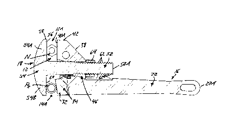
Shown in the drawings is a combination pipe and spud wrench 10
featuring a flat-sided adjustable jaw space 12 on a first side of the tool,
for use in
rotational working of flat-sided fasteners (e.g. hexagonal nuts and bolt
heads) in similar
manner to a convention spud wrench, and with a serrated adjustable jaw space
14 on
an opposing second side of the tool, for use in rotational working of round
pipes in
similar manner to a conventional pipe wrench. The tool is substantially
composed of a
main body 16 that is held in the user's hand to manipulate the tool, and a
cooperative
working body 18 that is movably supported on the main body in a manner
operable to
adjust the size of the two jaw spaces 12, 14 of the tool to fit differently
sized fasteners
and pipes. The main body 16 features an elongated shank 22 having a proximal
end
22A, and an opposing distal end 22B lying oppositely and distally thereof in
an axial
direction denoted by a longitudinal axis 24 of the shank 22 that lies
centrally thereof in
a midplane Pm of the shank that cuts therethrough from a front of the wrench
to an
opposing rear thereof. This axis 24, and the axial direction denoted thereby,
are used
as a reference to describe relative locations of various additional components
and
features of the tool.
In addition to the shank 22, the main body 16 also features a shoulder 20
that projects laterally outward from the shank on a first side 26 thereof,
specifically at a
distal portion 28 of the shank that neighbours the distal end 22B thereof. A
remaining
proximal portion 30 of the shank extends axially from the shoulder-equipped
distal
portion 28 to the proximal end 22A of the tool, whereby this proximal portion
30 of the
shank 22 defines a manually graspable handle of the tool. As shown, a
structural shape
Date recue / Date received 2021-11-22
7
of the shank 22 may be of an I-beam configuration, at least over the span of
the handle-
defining proximal portion 30, to impart notable bending strength to the
handle. At the
distal end 22B, the shank 22 terminates in a plane lying transversely of the
longitudinal
axis 24, and in the illustrated example, in an end plane PE lying obliquely
transverse of
the shank midplane Pm at an acute angle a thereto. Here, at the distal end 22B
of the
shank 22, is a first serrated jaw 32 whose serrated surface 32A faces axially
and distally
outward from the shank 22. In the non-limiting example of the illustrated
embodiment,
the first serrated jaw 32 is embodied by a separate jaw body attached to the
main body
by a cross-pin 34 that is engaged in aligned cross-bores of the main tool body
and a
base of the serrated jaw body. The serrated surface 32A of the jaw resides at
the same
acute angle a to the midplane Pm and longitudinal axis 24 as the distal shank
end 22B
to which the serrated jaw is attached.
An outer periphery of the shoulder 20 of the main body 16 features a
proximal face 36 that juts outward from the first side 26 of the shank 22 in a
plane lying
perpendicular to the midplane Pm and longitudinal axis 24, and faces axially
toward the
proximal end 22A of the shank 22; and an angled outer face 38 whose plane
obliquely
intersects that of the proximal face 36 at an outer end thereof furthest from
the shank
22, thereby forming a proximal outer corner 39 of the shoulder 20 from which
the angled
outer face 38 extends obliquely from the proximal face 36 in a distal
direction away from
the proximal end 22A of the shank. A distal face 40 of the shoulder's outer
periphery
resides oppositely of the proximal face 36 thereof, and spans inwardly back
toward the
shank 22, where this distal face 40 of the shoulder 20 then joins up with the
distal end
22B of the shank 22. At a laterally outermost extent of the shoulder's
periphery situated
furthest from the shank 22, an outermost face 42 of the shoulder's periphery
joins
together the angled outer face 38 and the distal face 40, and in doing so,
intersects the
Date recue / Date received 2021-11-22
8
distal face 40 at a right angle to form a distal outer corner 44 of the
shoulder 20. A flat
outer region 40A of the distal face 40 that neighbours this distal outer
corner 44 resides
in parallel relation to the proximal face 36 of the shoulder, and thus in
perpendicular
relation to the shank midplane Pm and longitudinal shank axis 24.
This flat outer region 40A, at least in the illustrated example, is a solid
surface that defines a first flat jaw of the flat-sided jaw space 12, though a
discrete jaw
member formed separately of the main tool body 16 may alternatively be affixed
to the
shoulder's distal face 40 at the outer region thereof to instead define the
first flat jaw.
In the illustrated example, the shoulder's distal face 40 has a profiled shape
that, from
an inner end of the flat outer region 40A, has a step-shaped transition area
40B that
transitions a short distance proximally back toward the proximal face 36,
followed by an
angled inner region 40C that that resides at an oblique angle to the shank
midplane Pm
and thereby slopes distally back toward, and connects to, the distal end 22B
of the
shank.
The shoulder 20 is the portion of the main body by which the working body
18 is supported on the main body 16 of the tool. For such purposes, the
shoulder 20
has a channel 46 passing fully therethrough in the axial direction from the
distal face 40
of the shoulder 20 to the proximal face 36 thereof. The channel passes axially
through
the shoulder 20 at a location between the shank 22 and the first flat jaw 40A,
and thus
penetrates through the profiled distal face 40 of the shoulder 20 at the
transitional and
sloped areas 40B, 40C, thereof, while leaving the first flat jaw 40A and the
first serrated
wrench jaw 20 fully intact on opposing sides of the channel 46.
In cross-sectional planes lying normal to the longitudinal axis 24, the
channel 46 is rectangular in shape, though the cross-sectional area of the
channel is
not-unform through the channel's length, and instead varies among said cross-
sectional
Date recue / Date received 2021-11-22
9
planes. This variation in channel width is attributable to profiled shapes in
boundary
walls of the channel at both an inner shank-adjacent side of the channel, and
an outer
shank-opposing side of the channel. The end of the channel that penetrates the
distal
face 40 of the shoulder 20 is referred to as a distal terminus of the channel
46, while
the opposing end of the channel that penetrates the proximal face 36 of the
shoulder is
referred to as a proximal terminus of the channel 46.
Starting from the distal terminus of the channel 46, the inner shank-
adjacent side of the channel 46 features a flat inner-wall segment 48A
residing in a
plane parallel to the shank midplane PM, followed by a neighbouring sloped
inner-wall
segment 48B that spans from the flat inner-wall segment 48A to the proximal
terminus
of the channel 46 at an angle lying obliquely of the flat inner-wall segment
48 and
sloping inwardly of the shank 22 toward the midplane Pm thereof. Starting from
the
proximal terminus of the channel 46, the outer shank-opposing side of the
channel 46
features a flat outer-wall segment 50A residing in a plane parallel to the
flat inner-wall
segment 50B, followed by a neighbouring sloped outer-wall segment 50B that
spans
from the flat outer-wall segment 50A to the distal terminus of the channel 46
at an angle
lying obliquely of the flat outer-wall segment 48 and sloping outwardly away
from the
shank 22 and the midplane Pm thereof. The axial spans of the flat inner and
outer wall
segments 48A, 50A overlap one another at a mid-region of the channel 46, where
the
width of the channel is uniform and at its narrowest. Moving from this narrow
mid-region
of the channel in either axial direction toward the proximal face or distal
face of the
shoulder 20, the channel grows wider due to the orientation of the sloped wall
segment
on one side of the channel that angles away from the opposing flat wall
segment on the
other side of the channel.
The working body 18 has an overall T-shaped structure featuring an
Date recue / Date received 2021-11-22
10
elongated stem 52 that lies alongside the shank 22 in a position passing fully
through
the channel 46 of the shoulder 20 and reaching axially past the distal end 22B
of the
shank 22. A double-sided head 54 of the working body 18 is affixed to the stem
52 in
a position lying cross-wise thereto at a distal end thereof situated axially
beyond the
distal end 22B of the shank 22. A first side 54A of the working body head 54
projects
laterally outward from the stem 52 at the same side thereof at which the first
flat jaw
40A resides on the main body 16, while a second side 54B of the head 54
projects
laterally outward from the stem 52 at the same side thereof at which the first
serrated
jaw 32 resides on the main body 16.
A proximally-facing edge of the first side 54A of the working body head
54 carries or defines a second flat jaw 56 of the tool. This second flat jaw
56 has a
solid planar working surface that faces proximally toward the first flat jaw
40A on the
main body 16 in opposing and aligned relation therewith, whereby the first and
second
flat jaws 40A, 56 cooperatively delimit the flat-sided jaw space 12 between
them. An
open mouth 12A of the flat-sided jaw space 12 is thus defined between the
distal outer
corner 44 of the main body's shoulder 20 at an outermost tip 58 of the first
side 54A of
the working body head 54. Accordingly, a hexagonal nut, hexagonal bolt head,
or other
flat-sided fastener is receivable into the flat-sided jaw space 12 through
this open mouth
12A thereof. Meanwhile, an opposing closed end of the flat-sided jaw space 12
is
defined by the working body stem 52, specifically at the area thereof that
protrudes
distally from the channel 46 in the shoulder 20 of the main body 16.
Similarly, a proximally-facing edge of the second side 54B of the working
body head 54 carries or defines a second serrated jaw 60 of the tool, which
features a
serrated working surface that faces proximally toward the first serrated jaw
32 on the
main body 16 in opposing and aligned relation therewith, whereby the first and
second
Date recue / Date received 2021-11-22
11
serrated jaws 32,60 cooperatively delimit the serrated jaw space 14 between
them. An
open mouth 14A of the serrated jaw space 14 resides oppositely of a closed end
thereof, the latter of which is once again defined by the working body stem
52,
specifically at the area thereof that protrudes distally from the channel 46
in the shoulder
20 o the main body 16. Due at least partly to the above-described oblique
angle of the
first serrated jaw 32 on the distal end 22B of the shank 22, the first and
second serrated
jaws 32, 60 lie in divergent relation to one another, in a manner growing
further apart
from one another in a direction moving laterally ooutward from the working
body stem
52 toward the open mouth 14A of the serrated jaw space 14.
A threaded proximal section of the working body stem 52 has external
thread segments 62 thereon at opposing sides thereof, specifically at both a
shank-
adjacent side of the stem 52 and an opposing shank-opposing side thereof.
These
thread segments 62 start at a proximal end 52A of the stem, and span at least
a partial
fraction of the stem's overall length toward the working head 54 at the
opposing distal
end of the stem 52. An internally-threaded adjustment nut 64 closes around the
threaded proximal section of the stem 52. The internal threading of the
adjustment nut
64 is operably engaged with the thread segments 62 of the working body stem
52. The
adjustment nut 64 preferably has a round and knurled outer circumference, and
is
rotatable around the working body stem 52, but is constrained from notable
axial
displacement relative to the main tool body shank 22.
To impose such axial constraint, the adjustment nut 64 is captured
between the proximal face 36 of the shoulder 20, and a pair of stop lugs 66
that project
laterally from the first side 26 of the main tool body shank 22 on opposing
sides of the
working body stem 52 at a distance spaced axially and proximally from the
proximal
face 36 of the shoulder 20. With the adjustment nut 64 axially constrained
relative to
Date recue / Date received 2021-11-22
12
the main tool body 16, manual rotation of the adjustment nut 64 causes
displacement
of working body stem 52 back and forth through the channel 46, whereby the
adjustment nut 64 is operable to move the working body head 54 toward and away
from
the stationary jaws 40A, 32 on the main body 16, thereby adjusting the size of
the flat-
sided and serrated jaw spaces 14, 16 delimited between these stationary jaws
40A, 32
on the main body 16 and the movable jaws 56, 60 on the working body 18.
The minimum width of the channel 46 between the two flat wall segments
48A, 50A thereof exceeds a width of the mounting head stem 52, which allows
some
degree of tilting of the working body stem 52 within the channel 46, as can be
seen by
comparison of Figures 4 and 6. The working body stem 52 is normally biased
into a
default non-tilted position in which the working body stem 52 lies parallel to
the
longitudinal shank axis 24, and thus parallel to a similar longitudinal axis
of the channel
46. The working body stem 52 is biased into this default position by a small
compression spring 68 that has an inner end thereof seated within a receiving
bore 70
in the flat wall segment 48A of the shank-adjacent side of the channel 46.
From this
bore 70, the spring 68 juts into the channel 46 to push against the shank-
adjacent side
of the working body stem 52, though in an indirect fashion via a resilient
spring cover
72. Inside the channel 46, this spring cover 72 spans axially across an outer
end of the
spring 68 in arcuate fashion. The spring cover 72 is retained in such position
by
abutment of opposing ends of the spring cover 72 against opposing ends of a
shallow
recess in the flat inner-wall segment 48A that spans axially across the
receiving bore
70.
The location of the spring 68 on the flat inner-wall segment 48A of the
shank-adjacent side of the channel 46 resides directly across the from the
flat outer-
wall segment 50A of the shank-opposing side of the channel 46. The shank-
opposing
Date recue / Date received 2021-11-22
13
side of the working body stem 52 is therefore spring biased into normally
abutting
contact against the flat outer-wall segment 50A of the shank-opposing side of
the
channel 46, as shown in Figure. The spring force thus normally holds the
working body
stem 52 in its default non-tilted position, absent exertion of any external
forces
exceeding the spring force. In this default non-tilted position of the working
body 18,
the first and second flat jaws 40A, 56 lie substantially parallel to one
another, and are
therefore respectively engagable against opposing flat sides of a flat-sided
fastener,
such the opposing flat sides of the hexagonal nut N shown in Figures 1, 2 and
4.
Meanwhile, in the same default non-tilted position of the working body 18, the
first and
second serrated jaws 32, 60 are in a divergent relationship angling away from
one
another toward the open mouth 14A of the serrated jaw space 14. This way, with
the
serrated jaw space widest at its open mouth 14A thereof, a round pipe PR is
more easily
introduced into the serrated jaw space 14, and into a wedged position between
the
serrated jaws 32, 60.
When placing the wrench into working relation with the round pipe PR, the
adjustment nut 64 is first used to adjust the open mouth 14A of the serrated
jaw space
14 to a size slightly exceeding the diameter of the round pipe PR concerned,
and the
open mouth 14A is lowered over the pipe PR to introduce the pipe into the
serrated jaw
space 14. During introduction of the pipe PR through the open mouth 14A and
into
contact with the divergent serrated jaws 32, 60, initial contact of the pipe
wall against
the serrated jaws 32, 60 forces these two jaws 32, 60 further apart from one
another,
against the bias force of the spring 68, thus acting to both widen the
serrated jaw space
14 and tilt the working body stem 52 out of it default position. Such tilting
takes place
about a fulcrum point 72 (Fig. 7) wherein the flat outer-wall segment 50A of
the shank-
opposing side of the channel 46 meets the sloped outer-wall segment 50B
thereof. This
Date recue / Date received 2021-11-22
14
tilting action takes place in a direction urging the proximal end 52A of the
working body
stem 52 toward the main body shank 22. The allowable amount of tilt is limited
by
eventual contact of one or both sides of the working body stem 52 with the
sloped wall
segment(s) on one or both sides of the channel 46, or by contact of the
proximal end
52A of the working body stem 52 with the first side 26 of the main tool body
shank 22.
Accordingly, once the tilting action of the working body 18 is ceased by such
contact
between the body stem 52 and one or more non-fulcrum points on the main tool
body,
further widening of the serrated jaw space 14 by the admitted pipe is
prevented, and
any further advancement of the pipe PR into the serrated jaw space 14 now
serves
solely to wedge the pipe PR firmly between the two serrated jaws 32, 60,
whereby their
serrated surfaces frictionally bite against the pipe wall at opposing sides
thereof.
The wrench is now ready to drive rotation of the pipe PR via exertion of
manual force on the proximal handle portion 30 of the shank 22 from the
shoulder-
equipped first side 26 of the shank. Forced movement of the wrench in this
direction is
referred to herein as a working stroke of the wrench. This moment direction of
this
exerted manual force on the proximal handle portion 30 of the shank 22 is of
opposite
relation to the previous tilting action induced on the working body 18 by the
wrench's
prior placement on the pipe. The exerted manual force of the working stroke
therefore
acts in a manner attempting to return the working body 18 and main tool body
16 to
their normal default relationship where the main body shank 22 and the working
body
stem 52 are parallel to one another. The manual force of the working stroke
therefore
attempts to drive the serrated jaws 32, 60 back toward one another, and
thereby
tightens the wrench's serrated frictional grip on the pipe while the wrench is
being
pushed or pulled through its working stroke from the shoulder-equipped side 26
of the
shank 22. A reverse stroke performed by application of manual force in the
opposing
Date recue / Date received 2021-11-22
15
direction from the other side of the shank reduces the wrench's frictional
bite on the
pipe PR. Manual depression of the proximal end 52A of the working body stem 52
toward the shank 22 can likewise be used to lessen the wrench's frictional
bite on the
pipe PR.
So for selective use of the wrench on a round pipe PR, the tiltability of the
working body stem 52 in the channel 46 in one permissible direction from its
default
spring-biased state allows the serrated jaw space 14 to widen from its default
width at
the user-selected displacement position of the working body (as set by the
adjustment
nut 64) up to a permitted maximum jaw space width at this selected
displacement
position (as limited by eventual contact of the tilted working body stem 52
with a non-
fulcrum point on the main tool body). Once the pipe is wedged between the
forced-apart
serrated jaws, performance of a manual working stroke of the wrench increases
the
frictional biting action on the pipe to confidently drive rotation of the pipe
via said working
stroke.
On the other hand, since the working body stem 52 abuts against the flat
wall segment 50A of the shank-opposing outer side of the channel 46 in the
stem's
default position, tilting of the working body stem 52 in the opposite
direction from this
default position is prohibited. Accordingly, when the flat-sided jaw space 12
of the
wrench is used on a nut, bolt or other flat-sided fastener, the only
permissible direction
of relative tilt between the working body 18 and the main body16 is in a
direction that
would cause the two flat jaws 40A, 56 to tilt toward one another from their
normally
parallel state in the default working body position. Accordingly, the only
possible
direction of relative movement between the flat-sided jaws 40A, 56 during use
of the
wrench on a flat-sided fastener is a movement direction that serves to
increase the
applied squeezing force on the fastener. Relative movement of the working body
in an
Date recue / Date received 2021-11-22
16
opposing direction causing the flat jaws 40A, 56 to tilt further apart from
their default
parallel relationship is prohibited.
Since various modifications can be made in my invention as herein above
described, and many apparently widely different embodiments of same made, it
is
intended that all matter contained in the accompanying specification shall be
interpreted
as illustrative only and not in a limiting sense.
Date recue / Date received 2021-11-22