Note: Descriptions are shown in the official language in which they were submitted.
CA 03140518 2021-11-15
Method and system for the synthesis of methanol
The invention relates to a process for synthesis of methanol according to the
preamble of claim 1, and to a plant for synthesis of methanol according to the
preamble of claim 15.
Methanol is prepared by an exothermic reaction that uses hydrogen and carbon
oxides as reactants, which are supplied as a gas stream to an appropriate
reactor
for methanol synthesis. These substances may be obtained from various sources.
A first option is to subject a carbonaceous energy carrier stream to steam
reforming or, for instance, to a catalytic partial oxidation, so as to obtain
a
synthesis gas comprising essentially hydrogen and carbon oxides. According to
the
type of energy carrier and mode of production of the synthesis gas, different
proportions of hydrogen and the carbon oxides - and hence a different
stoichionnetry - are achieved in the synthesis gas. The resulting
stoichionnetry can
then be adjusted by various measures, for instance by subjecting it to a water-
gas
shift reaction. One advantage of this approach is that the energy carrier
itself - for
instance natural gas - can regularly be provided at a high pressure, such that
only
a comparatively small increase in pressure is necessary after the synthesis
gas has
been obtained for attainment of the pressure required for the methanol
synthesis.
A further option for providing the reactants for the synthesis of methanol is
to use
a gas stream having a high carbon dioxide content and without hydrogen. Such a
gas stream can be obtained, for instance, from a flue gas, i.e. from an offgas
from
a combustion. It would likewise be possible to obtain such a gas stream from a
plant for preparation of bioethanol. Since such a flue gas thus does not
include any
hydrogen, it is necessary in this variant to provide hydrogen from another
source,
for example from an electrolysis.
1
Date Recue/Date Received 2021-11-15
CA 03140518 2021-11-15
Regularly, for the methanol synthesis, the gas comprising the reactants is
circulated in a circuit, since a single pass of this gas through the reactor
typically
does not lead to sufficiently substantial conversion to methanol. The methanol
converted is regularly removed from the circulating gas by condensation. At
the
same time, however, the circulation also results in accumulation of inert
substances that cannot be sufficiently removed by this condensation. For
removal
of these substances from the circuit, it is necessary to remove a portion of
the
circulating gas as purge gas, which purge gas can then be burned, for example.
WO 2014/173452 Al, which is the closest to the present invention, describes
such
.. a process and a corresponding plant for the synthesis of methanol from a
carbon
dioxide stream and a separate hydrogen stream.
WO 2018/019875 Al likewise discloses such a process and a corresponding plant.
A disadvantage of this prior art is that hydrogen is always also removed when
gas
is discharged. This discharged hydrogen is thus lost to the methanol
synthesis.
Proceeding from this prior art, it is therefore an object of the invention to
reduce
the proportion of hydrogen in the purge gas and hence to minimize the loss of
hydrogen, which is relatively valuable for the methanol synthesis.
With respect to a process for synthesis of methanol according to the preamble
of
claim 1, this object is achieved by the features of the characterizing part of
claim 1.
With respect to a plant for synthesis of methanol according to the preamble of
claim 15, this object is achieved by the features of the characterizing part
of
claim 15.
The invention is based on the finding that hydrogen can be recovered from a
tail
gas from a methanol reactor prior to removal thereof, and the hydrogen
recovered
2
Date Recue/Date Received 2021-11-15
CA 03140518 2021-11-15
can then be returned to the methanol synthesis. In this way, the hydrogen can
be
utilized for the methanol synthesis and is not just burnt.
The process proposed serves for synthesis of methanol, wherein a CO2 stream
consisting predominantly of carbon dioxide and an H stream consisting
.. predominantly of hydrogen are supplied to a methanol reactor arrangement
for
conversion to methanol. What is meant by the CO2 stream consisting
predominantly of carbon dioxide is that the molar proportion of carbon dioxide
of
the CO2 stream is at least 50%. The molar proportion of carbon dioxide in the
CO2
stream is preferably at least 95% and especially at least 99%. What is meant
by
the H stream consisting predominantly of hydrogen is correspondingly that the
molar proportion of hydrogen in the H stream is at least 50%. The molar
proportion
of hydrogen in the H stream is preferably at least 95% and especially at least
99%.
The conversion of the substances supplied to methanol is regularly incomplete.
In the process proposed, a tail gas stream comprising unreacted hydrogen is
obtained from the methanol reactor arrangement, and the unreacted hydrogen is
returned at least partly to the methanol reactor arrangement. The tail gas
stream
may, as well as the unreacted hydrogen, also include unreacted carbon dioxide,
and also carbon monoxide formed in the methanol reactor arrangement,
especially
by the reverse water-gas shift reaction. The tail gas stream for the methanol
synthesis may likewise include inert constituents such as nitrogen, methane
and
noble gases, and also by-products such as dinnethyl ether. It is preferable
that the
methanol reactor arrangement is encompassed by a plant for synthesis of
methanol.
The process proposed is characterized in that the tail gas stream is supplied
to a
hydrogen recovery arrangement to obtain a return stream comprising the
unreacted hydrogen. The process proposed is further characterized in that the
return stream consists predominantly of hydrogen. This means that the molar
proportion of hydrogen in the return stream is at least 50%. The molar
proportion
3
Date Recue/Date Received 2021-11-15
CA 03140518 2021-11-15
.. of hydrogen in the return stream is preferably at least 95% and especially
at least
99%. It is likewise preferable that the molar hydrogen content in the return
stream
is higher than in the tail gas stream. The hydrogen recovery arrangement
results
in enrichment of hydrogen. The plant for synthesis of methanol preferably
comprises the hydrogen recovery arrangement.
It is preferable that a purge stream is also obtained from the hydrogen
recovery
arrangement, which purge stream preferably has a smaller molar proportion of
hydrogen than the tail gas stream. In this way, a greater proportion of
hydrogen
is returned than is removed via the purge stream. In principle, the purge
stream
may be removed to any further use. For instance, the purge stream may be
routed
to a flare or to a catalytic postconnbustion.
It is preferable that the purge stream is fed as fuel to a firing apparatus of
a
chemical plant for obtaining a substance. The substance obtained is a
substance
other than methanol. This chemical plant is preferably an additional plant
with
respect to the plant for synthesis of methanol. But this chemical plant may
have
apparatuses in common with the proposed plant for synthesis of methanol,
especially the hydrogen recovery arrangement. This chemical plant is likewise
preferably a plant for obtaining a substance from a hydrocarbonaceous starting
.. stream. Alternatively or additionally, the chemical plant is set up to
recover a
hydrocarbonaceous product stream. The energy from the firing apparatus in the
chemical plant can be used for basically any purpose. It is preferable that
the
energy from the firing apparatus is used in the chemical plant for heating of
a
process stream and/or for raising steam. The chemical plant may especially be
a
steanncracker, a hydrogen plant or a dehydrogenation plant.
A preferred embodiment of the process proposed is characterized in that the
return
stream is supplied as H stream to the methanol reactor arrangement. In this
way,
the return stream can predominantly or even completely provide the hydrogen
for
the methanol synthesis. This is possible especially when the hydrogen recovery
4
Date Recue/Date Received 2021-11-15
CA 03140518 2021-11-15
arrangement is supplied not just with the tail gas stream but also with one or
more
further hydrogen-containing streams. The return stream may then include the
hydrogen from all these hydrogen-containing streams. It may be the case here
that the hydrogen recovery arrangement is encompassed by the chemical plant.
In such a case, it is thus possible to branch off a regularly relatively small
proportion of hydrogen from the hydrogen recovery arrangement in the chemical
plant, which does of course serve a different purpose than the synthesis of
methanol, for the synthesis of methanol.
It may especially be the case that a hydrogen-containing fresh gas stream is
fed
to the hydrogen recovery arrangement to obtain the return stream. The hydrogen-
containing fresh gas stream may especially be obtained from a hydrogen-
obtaining
arrangement, i.e. a plant for obtaining a hydrogen stream. The hydrogen-
obtaining
arrangement may be encompassed by the chemical plant. In this way, double
utilization also takes place for the recovery of hydrogen.
But it may also be the case that, in addition to the hydrogen from the return
stream, a fresh gas stream of hydrogen is supplied to the methanol reactor
arrangement. A corresponding further preferred embodiment of the process
proposed is characterized in that the H stream is a fresh gas stream from a
hydrogen-obtaining arrangement, and in that the return stream is returned
additionally to the H stream to the methanol reactor arrangement for
conversion
to methanol. This approach reduces the demands on the processing capacity of
the hydrogen recovery arrangement. The hydrogen-obtaining arrangement may
comprise a plant for obtaining hydrogen by electrolysis. The plant for
synthesis of
methanol preferably comprises the hydrogen-obtaining arrangement.
Alternatively, the chemical plant may comprise the hydrogen-obtaining
arrangement.
In principle, the hydrogen recovery arrangement can perform the hydrogen
recovery in accordance with any technical principle. In a preferred embodiment
of
5
Date Recue/Date Received 2021-11-15
CA 03140518 2021-11-15
the process proposed, the hydrogen recovery arrangement includes a pressure
swing adsorption (PSA) apparatus. It may especially be the case that the
hydrogen
recovery arrangement includes a pressure swing adsorption apparatus for
obtaining the return stream from the tail gas stream. The pressure swing
adsorption apparatus may likewise be set up to obtain the purge stream. Such a
pressure swing adsorption apparatus achieves a very high purity in the return
stream and is associated with a comparatively small pressure drop, such that
the
return stream has to be repressurized only to a small degree for the methanol
synthesis. In a further preferred embodiment of the process proposed, the
hydrogen recovery arrangement includes a further pressure swing adsorption
(PSA) apparatus, and the further pressure swing adsorption apparatus is
connected downstream of the pressure swing adsorption apparatus in the
processing operation. In this case, an output stream from the pressure swing
adsorption apparatus of the further pressure swing adsorption apparatus may be
set up to obtain a further return stream comprising hydrogen from the output
stream, in which case the further return stream is sent to the methanol
reactor
arrangement for conversion to methanol.
In a further preferred embodiment of the process proposed, the hydrogen
recovery
arrangement includes a membrane apparatus. It may especially be the case that
the hydrogen recovery arrangement includes a membrane apparatus for obtaining
the return stream from the tail gas stream. The membrane apparatus is
preferably
set up to separate off hydrogen.
Alternatively, it is possible to combine various modes of hydrogen recovery in
the
hydrogen recovery arrangement. For instance, in a preferred variant, the tail
gas
stream is fed to the membrane apparatus to obtain a membrane hydrogen stream
and a membrane tail stream, and the membrane tail stream is fed to the
pressure
swing adsorption apparatus to obtain a PSA hydrogen stream. In such a case,
either the membrane hydrogen stream or the PSA hydrogen stream may form the
return stream and the respective other stream the further return stream, in
which
6
Date Recue/Date Received 2021-11-15
CA 03140518 2021-11-15
case the further return stream is fed to the methanol reactor arrangement for
conversion to methanol. It is also possible to feed both return streams to the
methanol reactor arrangement for conversion to methanol. It is alternatively
possible to combine the membrane hydrogen stream and the PSA hydrogen stream
to give the return stream.
In a further preferred embodiment of the process proposed, the membrane
hydrogen stream is obtained from a low-pressure side of the membrane
apparatus,
and the membrane tail stream is obtained from a high-pressure side of the
membrane apparatus. It may thus be the case that the membrane hydrogen
stream is obtained at a lower pressure than the membrane tail stream.
As well as the return stream, it is also possible to return further streams to
the
methanol reactor arrangement. A preferred embodiment of the process proposed
is characterized in that a recycle stream comprising further unreacted tail
gas of
the methanol reactor arrangement is returned to the methanol reactor
arrangement for partial conversion to methanol. This is unreacted tail gas in
addition to the unreacted tail gas from the tail gas stream. It is preferable
here
that the recycle stream is pressurized by a recycle compressor arrangement
before
being returned to the methanol reactor arrangement. In this way, recirculation
of
the carbon dioxide and of any carbon monoxide formed in the methanol reactor
arrangement also takes place. The plant for synthesis of methanol preferably
encompasses the recycle compressor arrangement.
The recycle compressor arrangement may also be used to pressurize the return
stream. A further preferred embodiment of the process proposed is therefore
characterized in that the return stream is fed into the recycle stream. More
particularly, the return stream may be fed into the recycle stream prior to
pressurization by the recycle compressor arrangement.
7
Date Recue/Date Received 2021-11-15
CA 03140518 2021-11-15
In a preferred embodiment of the process proposed, the methanol reactor
arrangement comprises a methanol separation arrangement for obtaining the tail
gas stream and a crude methanol stream. It is likewise preferable that the
recycle
stream is obtained from the methanol separation arrangement. The tail gas
stream
may be obtained from the methanol separation arrangement in that the tail gas
stream is branched off from the recycle stream.
In a preferred embodiment of the process proposed, the crude methanol stream
is sent to a distillation to obtain the methanol. The plant for synthesis of
methanol
preferably encompasses the distillation.
It may be the case in principle that the methanol reactor arrangement
comprises
just a single reactor stage or else just a single reactor for the methanol
synthesis.
Within a single reactor stage, it is possible to connect multiple reactors for
the
methanol synthesis in parallel in the processing operation. In a further
preferred
embodiment of the process proposed, the methanol reactor arrangement has a
multitude of reactor stages for methanol synthesis that are connected in
series in
the processing operation. It is not necessary here for the reactor stages to
follow
on directly from one another in the processing operation.
In accordance with the multitude of reactor stages, it is also possible for
the
methanol separation arrangement to be in multistage form. For instance, it is
preferable that the methanol separation arrangement comprises a multitude of
methanol separation apparatuses, wherein each methanol separation apparatus of
the multitude of methanol separation apparatuses is connected downstream in
the
processing operation of a reactor stage of the multitude of reactor stages. In
other
words, each methanol separation apparatus is connected downstream in the
processing operation of a single one of the reactor stages and, if the reactor
stage
is not the last in the processing operation, upstream of the next reactor
stage. By
removing methanol and water after each individual reactor stage, it is
possible to
improve the reaction equilibrium for each downstream reactor stage.
8
Date Recue/Date Received 2021-11-15
CA 03140518 2021-11-15
A preferred embodiment of the process proposed is characterized in that a
crude
methanol substreann and a stage tail gas stream comprising unreacted hydrogen
are obtained from each of the methanol separation apparatuses of the multitude
of methanol separation apparatuses. The stage tail gas stream may also include
carbon monoxide, nitrogen, methane, noble gases and/or further constituents.
The
stage tail gas stream may likewise also include unreacted carbon dioxide. It
may
especially be the case that, up to a last reactor stage in the series of the
multitude
of reactor stages, each stage tail gas stream from one of the methanol
separation
apparatuses is fed to a downstream reactor stage in the processing operation.
In
other words, the removal of methanol takes place at first after each reaction
stage,
and the remaining tail gas is supplied to the respective next reactor stage if
there
is such a next reactor stage. It is further preferable that the crude methanol
substreanns are combined to give the crude methanol stream.
In principle, the reactor stages may have reactors of any type. A further
preferred
embodiment of the process proposed is characterized in that at least one of
the
reactor stages for methanol synthesis includes an isothermal reactor or
consists of
an isothermal reactor. It may especially be the case that all reactor stages
for
methanol synthesis each have an isothermal reactor or each consist of an
isothermal reactor.
In a further preferred embodiment of the process proposed, the CO2 stream and
the H stream, and preferably also the return stream, are fed to a first
reactor stage
of the multitude of reactor stages. It is likewise preferable that the
pressurized
recycle stream is fed to the first reactor stage.
A preferred embodiment of the process proposed is characterized in that the
tail
gas stream is obtained from a methanol separation apparatus which is connected
downstream of a tail gas recovery reactor stage in the processing operation,
wherein the tail gas recovery reactor stage is connected downstream of the
first
reactor stage in the processing operation. In other words, it is the case here
that
9
Date Recue/Date Received 2021-11-15
CA 03140518 2021-11-15
the tail gas stream is obtained after a particular reactor stage, which is
referred to
here as the tail gas recovery reactor stage. This tail gas recovery reactor
stage is
connected downstream of the first reactor stage, i.e. is a stage other than
the first
reactor stage. Specifically, the tail gas stream is obtained from that
methanol
separation apparatus which specifically follows this tail gas recovery reactor
stage
in the processing operation. The tail gas recovery reactor stage is preferably
the
last in the series in the processing operation among the multitude of reactor
stages. In other words, the last reactor stage is the tail gas recovery
reactor stage.
A further preferred embodiment of the process proposed is characterized in
that
the CO2 stream and the H stream, and preferably also the return stream, before
being fed to the methanol reactor arrangement, are pressurized by a feed gas
compressor arrangement. In principle, the feed gas compressor arrangement may
be in one-stage form, such that the feed gas compressor arrangement has only a
single compressor stage. Preferably, the CO2 stream and the H stream, and
preferably also the return stream, are pressurized by the feed gas compressor
arrangement to a synthesis pressure between 50 bar and 80 bar.
It is preferable that the feed gas compressor arrangement has a multitude of
compressor stages for pressurization that are connected in series in the
processing
operation. The feed gas compressor arrangement preferably has four compressor
stages. Such a multistage configuration means makes it possible for particular
streams that can be provided at a higher pressure not to have to pass through
all
compressor stages. The multitude of compressor stages may be a multitude of
compressor stages of a single compressor, such that the multitude of
compressor
stages has a common shaft. It is likewise alternatively possible for the
multitude
of compressor stages to be formed by a multitude of single compressors.
It is thus especially preferable that the H stream is supplied to the feed gas
compressor arrangement for pressurization between different compressor stages
of the multitude of compressor stages than the CO2 stream. This is an option
when
Date Recue/Date Received 2021-11-15
CA 03140518 2021-11-15
the H stream is provided at a different pressure than the CO2 stream. It is
alternatively possible that the H stream is supplied between those compressor
stages of the multitude of compressor stages for pressurization between which
the
CO2 stream is also supplied. This is advantageous when the H stream is
provided
at the same pressure as the CO2 stream. It may likewise be the case that the
return stream is supplied between different compressor stages of the multitude
of
compressor stages of the feed gas compressor arrangement for pressurization
than
the further return stream. The plant for synthesis of methanol preferably
encompasses the feed gas compressor arrangement.
In a preferred embodiment of the process proposed, the CO2 stream consists
essentially of carbon dioxide. It may alternatively or additionally be the
case that
the H stream consists essentially of hydrogen.
The plant proposed serves for synthesis of methanol and has a methanol reactor
arrangement which is supplied with a CO2 stream consisting predominantly of
carbon dioxide and an H stream consisting predominantly of hydrogen for
partial
conversion to methanol.
In the plant proposed, a tail gas stream comprising unreacted hydrogen is
obtained
from the methanol reactor arrangement, and the unreacted hydrogen in the tail
gas stream is at least partly returned to the methanol reactor arrangement.
The plant proposed is characterized in that the plant has a hydrogen recovery
arrangement which is supplied with the tail gas stream for obtaining a return
stream comprising the unreacted hydrogen, and in that the molar hydrogen
content in the return stream is higher than in the tail gas stream.
Features, advantages and properties of the plant proposed correspond to the
features, advantages and properties of the process proposed, and vice versa.
11
Date Recue/Date Received 2021-11-15
CA 03140518 2021-11-15
Further details, features, aims and advantages of the present invention are
elucidated hereinafter with reference to the drawing that shows working
examples
only. The drawing shows:
Fig. 1 a schematic of the flow diagram of a plant for execution of
the process
proposed in a first working example,
Fig. 2 a schematic of the flow diagram of a plant for execution of
the process
proposed in a second working example,
Fig. 3 a schematic of the flow diagram of a plant for execution of the
process
proposed in a third working example,
Fig. 4 a schematic of the flow diagram of a plant for execution of
the process
proposed in a fourth working example,
Fig. 5 a schematic of the flow diagram of a plant for execution of
the process
proposed in a fifth working example and
Fig. 6 a schematic of the flow diagram of a plant for execution of
the process
proposed in a sixth working example.
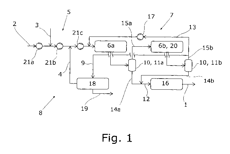
The plant according to a first working example of the plant proposed as shown
in
fig. 1 serves for synthesis of methanol 1 and can be operated by the process
proposed.
A CO2 stream 2 consisting essentially of carbon dioxide, an H stream 3
consisting
essentially of hydrogen, and a return stream 4 likewise consisting essentially
of
hydrogen are pressurized by a feed gas compressor arrangement 5 and then fed
to a first reactor stage 6a of a methanol reactor arrangement 7.
12
Date Recue/Date Received 2021-11-15
CA 03140518 2021-11-15
This feed gas compressor arrangement 5 is in multistage form. By way of
simplification, the feed gas compressor arrangement 5 here is represented by
three compressor stages 21a-c of a single compressor that are series-connected
in the processing operation, where a feed gas compressor arrangement 5 may
regularly have four compressor stages. It is apparent that the CO2 stream 2,
the
H stream 3 and the return stream 4 are each supplied upstream of a different
compressor stage 21a-c. The CO2 stream 2 is fed in at ambient pressure, and
therefore is to be pressurized by all compressor stages 21a-c of the feed gas
compressor arrangement 5 for attainment of the target pressure for the
methanol
synthesis, and it is consequently supplied directly to the first compressor
stage
21a. The H stream 3 is fed in at a somewhat higher pressure and is therefore
fed
in downstream of the first compressor stage 21a and upstream of the second
compressor stage 21b in the processing operation. Finally, the return stream 4
is
fed in at the highest pressure, and therefore between the second compressor
stage
21b and the third compressor stage 21c in the processing operation.
Likewise fed into the first reactor stage 6a is a recycle stream 13. In this
first
reactor stage 6a consisting of a single isothermal reactor, partial conversion
of the
carbon dioxide and of the hydrogen to methanol takes place.
The CO2 stream 2 is obtained from the flue gas from a power plant (not shown
here). The H stream 3 is obtained from an electrolysis plant for obtaining
hydrogen
(likewise not shown here), wherein the H stream 3 in this example could also
be
obtained at ambient pressure. It is alternatively conceivable that the H
stream 3
is provided at a lower pressure than the CO2 stream 2, in which case the feed
to
the compressor stages 21a-c would be switched. The return stream 4 is obtained
from a hydrogen recovery arrangement 8 of the plant, which is supplied for
this
purpose with a tail gas stream 9 from the methanol reactor arrangement 7,
which
includes unreacted reactants from the methanol synthesis and therefore
unreacted
hydrogen in particular.
13
Date Recue/Date Received 2021-11-15
CA 03140518 2021-11-15
Connected downstream of the first reactor stage 6a in the processing
operation,
albeit not directly, is a second reactor stage 6b of the methanol reactor
arrangement 7, which second reactor stage 6b here likewise consists of a
single
isothermal reactor. The methanol reactor arrangement 7 has a methanol
separation arrangement 10 which, through condensation of crude methanol, is
set
up to obtain the tail gas stream 9 and a crude methanol stream 12. The
methanol
separation arrangement 10 in turn consists here of a first methanol separation
apparatus ha connected between the first reactor stage 6a and the second
reactor
stage 6b in the processing operation, and a second methanol separation
apparatus
lib connected downstream of the second reactor stage 6b in the processing
operation.
The gas mixture comprising methanol and unreacted tail gas from the first
reactor
stage 6a is fed to the first methanol separation apparatus 11a, and a first
crude
methanol substreann 14a, consisting essentially of crude methanol, and a first
stage tail gas stream 15a comprising the unreacted tail gases from the first
reactor
stage 6a are obtained from this methanol separation apparatus 11a. The first
stage
tail gas stream 15a is fed to the second reactor stage 6b for methanol
synthesis.
Correspondingly, the gas mixture from the second reactor stage 6b is fed to
the
second methanol separation apparatus 11b, and a second crude methanol
substreann 14b and a second stage tail gas stream 15b are obtained therefrom.
The first crude methanol substreann 14a and the second crude methanol
substreann
14b are combined to give the crude methanol stream 12, which is in turn fed to
a
distillation 16 to obtain the methanol 1.
The second stage tail gas stream 15b is divided into the tail gas stream 9,
which
is of course fed to the hydrogen recovery arrangement 8, and the recycle
stream
13. In this way, both the tail gas stream 9 and the recycle stream 13 are
obtained
from the methanol separation arrangement 10. The recycle stream 13 is fed to a
recycle compressor arrangement 17 for increasing the pressure and then to the
first reactor stage 6a. Since the tail gas stream 9 from the second reactor
stage
14
Date Recue/Date Received 2021-11-15
CA 03140518 2021-11-15
6b is thus obtained directly downstream here, the second reactor stage 6b can
be
referred to as tail gas-obtaining reactor stage 20.
In the working example of fig. 1, the hydrogen recovery arrangement 8 is a
pressure swing adsorption apparatus 18 that affords the return stream 4 from
the
tail gas stream 9. Likewise obtained is a purge stream 19, which is fed to a
firing
apparatus (not shown here) of a separate chemical plant, where it is
incinerated.
The composition of the purge stream 19 corresponds essentially to the
composition
of the tail gas stream 9 minus the return stream 4. The hydrogen fed back to
the
methanol reactor arrangement 7 via the return stream 4 is not fired with the
purge
stream 19 but is available for the methanol synthesis.
The plant according to a second working example of the plant proposed as shown
in fig. 2 may be operated by the process proposed. This working example
corresponds in principle to the first working example of fig. 1, except that
the
return stream 4 from the hydrogen recovery arrangement 8 is not pressurized by
the feed gas compressor arrangement 5 before being fed to the first reactor
stage
6a. Instead, the return stream 4 is fed into the recycle stream 13. This feed
is
effected upstream of the recycle compressor arrangement 17 in the processing
operation, such that the return stream 4 is pressurized by the recycle
compressor
arrangement 17 together with the recycle stream 13. Compared to the working
example of fig. 1, this firstly reduces the burden on the feed gas compressor
arrangement 5. It may likewise be the case that the pressure of the return
stream
4 is close to the pressure of the recycle stream 13, such that the latter has
to be
expanded only slightly, and therefore combination of the return stream 4 with
the
recycle stream 13 is more favorable than supply of the return stream to the
feed
gas compressor arrangement 5.
The plant according to a third working example of the plant proposed as shown
in
fig. 3 may be operated by the process proposed. This working example likewise
corresponds in principle to the first working example of fig. 1, except that
the
Date Recue/Date Received 2021-11-15
CA 03140518 2021-11-15
hydrogen recovery arrangement 8 here consists of a membrane apparatus 22 for
obtaining the return stream 4 and the purge stream 19. Especially when a
relatively large pressure drop of the return stream 4 compared to the tail gas
stream 9 is accepted - which can in principle be compensated for by the
increase
in pressure in the feed gas compressor arrangement 5 - it is possible to
recover a
particularly high proportion of the hydrogen in the tail gas stream 9 via the
return
stream 4. Correspondingly, the loss of hydrogen in the purge stream 19 is low.
The plant according to a fourth working example of the plant proposed as shown
in fig. 4 proceeds from the third working example of fig. 3 and can likewise
be
operated by the process proposed. Here, the hydrogen recovery apparatus 8
comprises both a membrane apparatus 22 and a pressure swing adsorption
apparatus 18. Specifically, the tail gas stream 9 is fed to the membrane
apparatus
22. A hydrogen-enriched membrane hydrogen stream 23 and a correspondingly
low-hydrogen membrane tail stream 24 are obtained from the membrane
apparatus 22. The membrane tail stream 24 is fed to the pressure swing
adsorption
apparatus 18, such that a PSA hydrogen stream 25 consisting essentially of
hydrogen and the purge stream 19 are obtained therefrom in turn. The PSA
hydrogen stream 25 is combined here with the membrane hydrogen stream 23 to
give the return stream 4. But it would also be possible to guide only the
membrane
hydrogen stream 23 as return stream 4 and the PSA hydrogen stream 25
separately as further return stream to the feed gas compressor arrangement 5.
In
this case, it would be possible to feed in the membrane hydrogen stream 23 and
the PSA hydrogen stream 25 upstream of different compressor stages 21a-c owing
to their different pressure. Because the membrane apparatus 22 is connected
.. upstream of the pressure swing adsorption apparatus 18 in the manner
described
for the fourth working example, the burden on the pressure swing adsorption
apparatus 18 is reduced to such an extent that can have a smaller design. It
is
thus possible to return a very high proportion of the hydrogen in the tail gas
stream
9 overall.
16
Date Recue/Date Received 2021-11-15
CA 03140518 2021-11-15
The plant according to a fifth working example of the plant proposed as shown
in
fig. 5 may be operated by the method proposed and proceeds in principle from
the
first working example of fig. 1, except that - as will be described in detail -
the H
stream 3 is not obtained from an electrolysis. However, the hydrogen recovery
arrangement 8 designed as a pressure swing adsorption apparatus 18 is also
used
here for the hydrogen-containing fresh gas stream 26, which fresh gas stream
26
is obtained from a hydrogen-obtaining arrangement 27. The hydrogen-obtaining
arrangement 27 consists of a steam reformer 28 which is supplied with a
natural
gas stream 31 and from which a synthesis gas stream 32 comprising carbon
oxides
and hydrogen is obtained. This synthesis gas stream 32, in order to increase
its
hydrogen content, is fed to a reactor 29 of the hydrogen-obtaining arrangement
27 for the water-gas shift reaction, from which reactor 29 the fresh gas
stream 26
is then obtained. The purge gas 19 from the pressure swing adsorption
apparatus
18 can then be used together with a fuel gas 30 for operation of the steam
reformer
28. In a departure from the working examples of figs. 1 to 4, the pressure
swing
adsorption apparatus 18 and the hydrogen-obtaining arrangement 27 added in
this working example are also part of a chemical plant 33, with the pressure
swing
adsorption apparatus 18 being part of this chemical plant 33 and part of the
plant
proposed for synthesis of methanol.
By virtue of the common use of the pressure swing adsorption apparatus 18, the
return stream 4 from the hydrogen recovery arrangement 8 forms the H stream
3, such that the return stream 4 is thus fed as H stream 3 to the methanol
reactor
arrangement 7. As shown in fig. 5, only a portion of the hydrogen obtained
from
the hydrogen recovery arrangement 8 forms the return stream 4, and the further
hydrogen can be fed to a use in the chemical plant 33.
Finally, the plant according to a sixth working example of the plant proposed
as
shown in fig. 6 may likewise be operated by the process proposed and proceeds
from the fifth working example. However, the hydrogen recovery arrangement 8
here, similarly to the fourth working example, has a membrane apparatus 22 and
17
Date Recue/Date Received 2021-11-15
CA 03140518 2021-11-15
a pressure swing adsorption apparatus 18. In accordance with the fourth
working
example, the membrane tail stream 24 here too is fed to the pressure swing
adsorption apparatus 18, specifically together with the fresh gas stream 26.
The
PSA hydrogen stream 25 then forms the return stream 4 which, after its
pressure
has been increased by the feed gas compressor arrangement 5, is fed as H
stream
3 to the methanol reactor arrangement 7. The membrane hydrogen stream 23
forms a further return stream 34 which, after its pressure has been increased
by
the feed gas compressor arrangement 5, is fed to the methanol reactor
arrangement 7.
18
Date Recue/Date Received 2021-11-15