Note: Descriptions are shown in the official language in which they were submitted.
CA 03140796 2021-11-16
1
METHOD FOR PRODUCING IMPROVED COLD-FORMING TOOLS FOR
HIGH-STRENGTH AND SUPER-HIGH-STRENGTH STEELS, AND COLD FORMING TOOL
The invention relates to a method for producing cold forming tools,
particularly for cold
forming super-high-strength steels and to the cold forming tool for doing so.
Particularly in automotive engineering, there is a continual endeavor to make
vehicle bodies
ever lighter in weight. In the last few years, efforts in this area have led
to the production of
high-strength steel components, for example by means of press hardening
methods, which
because of their high strength require comparatively low material thicknesses
and thus
weights. Now, particularly for reasons of environmental protection and
reducing fuel con-
sumption, lightweight construction is a top priority for automobile
manufacturers. In particu-
lar, so-called high-strength, super-high-strength, and ultra-high-strength
steel materials are
being used (UHSS ¨ ultra-high-strength steel, AHSS ¨ advanced-high-strength
steel). For the
purposes of this application, the term "high-strength steel" relates to steel
materials with a
tensile strength of more than 350 MPa, in particular more than 600 MPa. These
materials
are particularly used to produce components such as bumper reinforcements,
side impact
bars, seat frames and mechanisms, as well as chassis components.
With materials of this kind, the weight can be reduced by up to 40% compared
to conven-
tional components. It is also possible to reduce costs and increase production
efficiency.
There are two main processes used in the forming of metals, namely hot forming
and cold
forming.
"Hot forming" refers to all of the forming steps that take place above the
recrystallization
temperature of a metal. In general, lower forming forces are required for it;
in addition, no
cold work hardening of the workpiece occurs during the forming.
Date Recue/Date Received 2021-11-16
CA 03140796 2021-11-16
2
In this connection, A1203-based solutions are often used for the hot forming
tools, which,
due to their oxidic components, increase the hot hardness and oxidation
resistance of the
overall coating for the high-temperature application of hot forming. These
oxidic layers,
however, are hard and brittle. Usually, the purpose of coatings on hot forming
tools is to
allow them to withstand the thermal stress and to also function as a diffusion
barrier.
One challenge in this context, however, is the cold forming of such super-high-
strength
steels.
Because of their property, these materials resist the forming tools with
considerably higher
forces than would be the case with conventional auto body steel.
Because of the high contact pressures that occur between the workpiece and
tool during the
cold forming of super-high-strength steels, in particular the tribological
stresses on the tools
are very high. For this reason, PVD layers are used in cold forming, which are
focused on
increasing the mechanical load capacity, increasing wear, and reducing crack
propagation,
instead of relying on oxidic layers ¨ as in hot forming ¨ which have a higher
hot hardness in
order to counteract thermal fatigue in the tools. Since economical production
requires tools
with long service lives, it is necessary to ensure that the wear due to the
extremely high
contact stresses in the normal direction is reduced. For cold forming, one
approach in this
context is to pretreat workpieces and in particular to also add lubricants
containing high lev-
els of additives.
The addition of lubricants can have negative effects on worker health since
when they are
used, lubricant emissions can get into the workers' breathing air and onto
their skin at their
work stations. In addition, this can result in the spread of cold lubricants
into the area sur-
rounding the machine, which further degrades the life cycle assessment of the
entire pro-
cess.
The object of the invention is to create a method that can be used to produce
cold forming
tools, which exhibit a reduced wear propensity and whereby it is possible to
significantly
Date Recue/Date Received 2021-11-16
CA 03140796 2021-11-16
3
increase tool service life. Another object of the invention is to reduce the
lubrication expense
in forming processes, particularly of super-high-strength steels.
The object is attained with a method having the features of claim 1.
Advantageous modifications are disclosed in the sub-claims that are dependent
thereon.
Another object is to create a corresponding cold forming tool.
This object is attained with a cold forming tool having the features of claim
9.
Advantageous modifications are disclosed in the sub-claims that are dependent
thereon.
The invention relates to the particular requirements in cold forming processes
due to the
high forming forces, particularly in the cold forming of super-high-strength
steels. To meet
these requirements, the cold forming tool according to the invention is
provided with a mul-
tilayer hard material layer composed of an applied titanium nitride adhesive
layer and layers
of aluminum titanium nitride and aluminum chromium nitride that are deposited
thereon. By
means of this specific multilayer structure, it is possible to achieve the
strength and load-
bearing capacity of the overall coating, which is required by the application
of cold forming
super-high-strength sheet metals.
In addition, the crack growth, which is observed with the high strain forces
in the cold form-
ing of super-high-strength sheet metals, can be stopped by the overall coating
due to the
alternating layers of aluminum titanium nitride and aluminum chromium nitride
in that the
cracks are stopped at the transitions between the individual layers due to
their differing mi-
crostructures. In order to reduce the breakaway torque, a top layer of
titanium nitride or
alternatively titanium carbon nitride is provided as a top layer.
Date Recue/Date Received 2021-11-16
CA 03140796 2021-11-16
4
In the original German description, the terms "Schicht,""Layer," and "LageF
are used syn-
onymously refer to a single layer of the multilayer composite coating.
The focus of the present invention is the mechanical and tribological
requirements of cold
forming in which the hot hardness and oxidation resistance of the overall
coating and indi-
vidual layers are negligible due to the application of cold forming. Oxidic
layers are extreme-
ly hard and brittle. In the cold forming, the main stress on the tool is
produced by the pow-
erful forming forces occurring and by the cold work hardening, as a result of
which the use
of oxidic layers, whose advantages lie in their thermal resistance, is less
common and more
focus is being placed on wear-resistant nitride-based multilayer coatings,
which inhibit crack
growth and increase the mechanical load capacity. Also, the use of oxidic
layers in the cold
forming sector is only possible to a limited degree since the synthesis of for
example A1203
layers for this application area requires the production of the alpha-A1203
phase, which can
be achieved with conventional PVD/CVD methods only at deposition temperatures
>1000 C.
Due to the high deposition temperatures and the accompanying thermal warpage
and hard-
ness reduction of the tools and because of the near-net-shape requirements,
these process-
es can only be used to a limited degree for coating cold forming tools. A
coating of the
gamma-A1203 phase at temperatures < 800 C is also only possible to a limited
degree for
use in cold forming since it does not procure mechanical properties and wear
resistance that
are comparable to those achieved by other nitridic PVD systems.
According to the invention, the surface of a cold forming tool, particularly
for forming super-
high-strength steels, is changed in that hard material layers with reduced
friction coefficients
are applied to the surface. The underlying idea is to offer better resistance
to local stresses
by producing property gradients on the tool surface. The surface in this case
is for example
provided with a higher degree of hardness while the tool substrate ensures the
required
degree of toughness.
In particular, according to the invention, a PVD hard material layer is
deposited onto corre-
sponding tools.
Date Recue/Date Received 2021-11-16
CA 03140796 2021-11-16
The production of PVD coatings (physical vapor deposition) has been known for
a long time
and is used especially for tools, in particular cutting tools.
A method that is usually used for such hard material layers is cathodic arc
evaporation, also
5 referred to as arc-PVD or arc evaporation. This method belongs to the
group of physical
gas-phase deposition (PVD) methods and stated more precisely, is an
evaporation method.
With this method, a negative potential is applied to the cathode or the
material to be evapo-
rated; an arc is produced between the chamber wall of the vacuum chamber
(correspond-
ingly functioning as an anode) and the cathode surface. The cathode contains
the material
that is to be subsequently deposited, for example, onto the workpiece, in this
case the tool;
by means of a corresponding atmosphere in the chamber, for example, the
cathode material
in the plasma phase can also react with corresponding gases (reaction gases)
in order to
produce a corresponding layer.
In this cathodic arc evaporation, a large part of the evaporated material is
ionized, during
which, in a line-of-sight process, the material diffuses radially from the
cathode surface. In
addition, a negative potential is applied to the substrate so that the ionized
metal vapor is
accelerated toward the substrate. The vapor condenses on the substrate
surface; as a result
of the high ionization percentage and the negative bias voltage at the
substrate, a high ki-
netic energy can be introduced into the growing layer. By means of this, it is
possible among
other things to influence the properties such as the layer adhesion, density,
composition,
and microstructure of the deposited layer.
It is known, however, that normally, aluminum chromium nitride (AlCrN) and
aluminum titani-
um nitride (AlTiN) layers can only be applied with a high percentage of
macroparticle inclusions
(so-called "droplets") in the growing layer and that in the evaporation of
aluminum chromium
cathodes, a powerful formation of macroparticles is observed. This is
manifested in so-called
droplet/macroparticle inclusions in the growing thin layer and a
correspondingly higher degree
of layer roughness. These droplets also form in monolithic embodiments of
aluminum chromi-
um nitride and aluminum titanium nitride layers. Aluminum chromium nitride and
aluminum
titanium nitride layers also have a comparatively high degree of layer
hardness and higher fric-
Date Recue/Date Received 2021-11-16
CA 03140796 2021-11-16
6
tion coefficients in actual use. The higher degrees of layer roughness and the
higher friction
coefficients in the region close to the surface, however, can have a
disadvantageous effect dur-
ing the forming of for example super-high-strength galvanized sheet steels and
can lead to
instances of welding buildup, which can reduce tool service life. The welding
buildup is an ad-
hesive material residue composed of softer formed material on the harder tool.
According to the invention, therefore, an additional thin titanium nitride top
layer (TIN) is ap-
plied as a final layer, which due to its reduced droplet inclusions yields a
more uniform,
smoother layer surface. Another property of the titanium nitride top layer is
its friction coeffi-
cient, which is lower than those of the underlying layers. This reduces the
risk of welding
buildup and thus improves the break-in behavior of the layer in comparison to
the underlying
harder aluminum titanium nitride and aluminum chromium nitride layers. The
break-in behav-
ior is advantageously improved by the titanium nitride top layer because of
its good sliding
properties and its low breakaway torque (the force, which is necessary to
overcome the static
__ friction and initiates the transition to sliding friction). Surprisingly,
the titanium nitride top lay-
er absorbs some force with each stroke since the titanium nitride top layer
has a better elas-
ticity than the hard aluminum chromium nitride and aluminum titanium nitride
layers beneath
it. A TiN top layer thinner than 0.1 pm does not result in an improved break-
in behavior. With
TIN top layers that are too thick (thicker than 0.5 pm), the underlying
multilayer structure can
no longer exhibit its advantageous properties such as the slower crack growth.
TIN top layers
with a thickness of between 0.2 and 0.3 pm can be particularly advantageous.
This represents
an optimum balance of good break-in properties and delayed tool damage, for
example due
to the inhibition of crack growth.
Instead of the titanium nitride top layer (TIN), it is also alternatively
possible to provide a tita-
nium carbon nitride top layer (TiCN). The use of a titanium nitride top layer
(TIN) is preferable,
for example, for the cold forming of coated ultra-high-strength sheet metals
since this reduc-
es friction due to its lower hardness in comparison to the titanium carbon
nitride top layer
(TiCN) and thus reduces the potential welding buildup on the coating (e.g.
electrochemically
galvanized with zinc) of the ultra-high-strength sheet metal on the tool.
Moreover, the choice
between the two top layers permits a color diversification for the user if so
desired since the
TIN top layer has a golden color and the TiCN top layer has a gray-blue color.
Date Recue/Date Received 2021-11-16
CA 03140796 2021-11-16
7
In addition, a titanium nitride adhesive layer (TIN) can be advantageously
deposited onto
the tool that is to be coated.
This adhesive layer can result in a better bonding of the subsequent multiple
layers of the
coating. The TIN adhesive layer advantageously has a thickness of 0.2 to 0.9
pm. With lay-
ers thicker than 0.9 pm, internal stresses in the layer can occur that are so
high that the
layer adhesion deteriorates. A titanium nitride adhesive layer that is 0.4 to
0.7 pm thick
turns out to be particularly advantageous; this made it possible to achieve
the best layer
adhesion. The upper limit can also be selected to be 0.9, 0.8, 0.7, or 0.6 pm
thick. The low-
er limit can also be selected to be 0.2, 0.3, 0.4, or 0.45 pm thick.
For the application of the individual layers of the multilayer coating,
preferably aluminum
chromium, aluminum titanium, and titanium cathodes are used, with nitrogen
being used as
a reactive gas, in order to deposit aluminum titanium nitride or aluminum
chromium nitride
layers (AlTiN-AlCrN multilayer systems). These nitride hard material layers,
due to their me-
chanical and thermal properties, can produce wear-minimizing and local thermal
effects with
respect to the extreme contact stresses in the normal direction. It has turned
out to be ad-
vantageous to first deposit an aluminum titanium nitride layer onto the
optional TIN adhe-
sive layer. It is thus possible to improve the bonding of the subsequent
multiple layers.
The interplay of layers with different mechanical and thermal properties is
advantageous
among other things in order to reduce crack propagation. In this connection,
the inventors
have discovered that 5 respective layers of AlCrN and AlTiN (i.e. a total of
10 layers) can ef-
fectively reduce crack propagation. But too many layers have the disadvantage
that with in-
creasing layer thickness, the internal stresses in the applied layer can
become high enough
that layer adhesion problems can occur. It has advantageously turned out that
for this pur-
pose, the number of alternating layers should not exceed 20 (i.e. a total of
40 ¨ or 42 with a
TIN adhesive layer and a TIN or alternatively TiCN top layer). The upper limit
for alternating
layers can also be selected to be 20, 18, 16, 14, or 12 layers of AlCrN and
AlTiN. The lower
limit for alternating layers can also be selected to be 5, 6, 7, 8, 9, or 10
layers of AlCrN and
AlTiN.
Date Recue/Date Received 2021-11-16
CA 03140796 2021-11-16
8
The individual aluminum titanium nitride layers can advantageously each be 0.1
to 0.5 pm
thick. With layers thinner than 0.1 pm, it may not be possible to achieve the
desired proper-
ties (somewhat more elastic than AlCrN) of the hard material layer. Thicker
layers, particularly
those over 0.5 pm thick, can have internal stresses that are so high that the
layer adhesion
deteriorates. Layer thicknesses of between 0.2 and 0.3 pm can be particularly
advantageous
since they can already have a functional effect without introducing
excessively high internal
stresses. The upper limit can also be selected to be 0.50, 0.40, 0.35, or 0.30
pm thick. The
lower limit can also be selected to be 0.10, 0.15, or 0.20 pm thick.
The individual aluminum chromium nitride layers can advantageously each be 0.1
to 0.5 pm
thick. With layers thinner than 0.1 pm, it may not be possible to achieve the
desired proper-
ties (resistant to abrasive wear, very hard, tougher than AlTiN, high degree
of hot hardness ¨
temperature stability up to approx. 900 C) of the hard material layer. Thicker
layers, particu-
larly those over 0.5 pm thick, can have internal stresses that are so high
that the layer adhe-
sion deteriorates. Layer thicknesses of between 0.2 and 0.3 pm can be
particularly advanta-
geous since they can already have a functional effect without introducing
excessively high
internal stresses. The upper limit can also be selected to be 0.50, 0.40,
0.35, or 0.30 pm
thick. The lower limit can also be selected to be 0.10, 0.15, or 0.20 pm
thick.
In a particularly advantageous embodiment, a layer thickness combination of
0.2 to 0.3 pm
for each aluminum chromium nitride and aluminum titanium nitride layer is
selected. Through
the interplay of somewhat more elastic layers and somewhat tougher layers, it
is possible, for
example, to slow crack growth and thus to ensure a longer service life of the
tool.
The overall layer thickness can be between 1.5 and 21 pm. Preferably, the
overall layer thick-
ness is 10 to 11 pm. Preferably, the thickness of the AlTiN-AlCrN multilayer
system is more
than 5 pm since this slows the crack propagation.
The chemical composition of the layers is 40 to 50 at% titanium and 50 to 60
at% nitrogen in
the titanium nitride (adhesive layer and top layer), 20 to 23 at% carbon, 30
to 33 at% nitro-
gen, and 44 ¨ 50 at% titanium in the titanium carbon nitride (alternative top
layer), 30 to 40
at% aluminum, 10 to 20 at% chromium, and 45 to 55 at% nitrogen in the aluminum
chromi-
Date Recue/Date Received 2021-11-16
CA 03140796 2021-11-16
9
urn nitride, and 8 to 14 at% aluminum, 30 to 40 at% titanium, and 40 to 50 at%
nitrogen in
the aluminum titanium nitride. In other words: TizNi_õ where z = 0.4 to 0.6,
TixCyNi_(x+y),
where x = 44 to 50, y = 20 to 23, and the rest is nitrogen, AlaCrbNi_(a+b),
where a = 30 to 40,
b = 10 to 20, and the rest is nitrogen, and AlcTidNi_(c+d), where c = 8 to 14,
d = 30 to 40, and
the rest is nitrogen.
The layer structure according to the invention on the cold forming tool can be
deposited with
a duplex method (in-situ plasma nitriding and subsequent PVD coating).
Preferred substrates
include all materials that can be plasma nitrided, in particular metal
materials, especially HSS
(high speed steel) and carbide metal. For purposes of this disclosure, the
metal material that
is to be coated is referred to as the substrate. The applicant produces the
alpha 400P and
alpha 900P coating systems for this purpose. In the duplex method, the two
work steps
(plasma nitriding and PVD coating) are performed one after another in one
process without
having to ventilate the system in between them. In the plasma nitriding,
nitrogen diffuses into
the boundary zone, which increases the surface hardness of the tool material.
The formation
of unwanted compound layers is suppressed in this case. It is thus possible to
optimally pre-
pare the workpiece (good supporting effect) for the subsequent hard, brittle
PVD coating.
The invention thus relates to a method for producing a cold forming tool,
particularly for cold
forming super-high-strength steels, wherein the cold forming tool is the upper
and/or lower
tool of a forming tool set, wherein the cold forming tool is made of a metal
material and has a
forming surface that is designed so that a formed metal sheet has the desired
final contour of
the component, wherein that a hard material layer is deposited on the forming
surface of the
forming tool by means of physical gas-phase deposition, wherein the hard
material layer con-
sists of a titanium nitride adhesive layer and alternating layers of aluminum
titanium nitride
and aluminum chromium nitride deposited thereon, wherein a titanium nitride
top layer or
titanium carbon nitride top layer is deposited as the final layer as the
outermost outer surface
oriented toward a workpiece that is to be formed.
According to another advantageous embodiment, as the first layer of the
alternating deposit-
ed layers, first an aluminum titanium nitride layer is deposited onto the
titanium nitride adhe-
sive layer.
Date Recue/Date Received 2021-11-16
CA 03140796 2021-11-16
In another advantageous embodiment, five to twenty alternating layers are
deposited onto
the titanium nitride adhesive layer before a final titanium nitride top layer
or titanium carbon
nitride top layer is deposited.
5
It is advantageous if the titanium nitride adhesive layer (2) has a thickness
of 0.2 microme-
ters to 0.9 micrometers, preferably from 0.4 micrometers to 0.7 micrometers.
It is likewise advantageous if the aluminum titanium nitride layers (3) have a
thickness of
10 0.1 to 0.5 micrometers, preferably from 0.2 to 0.3 micrometers.
The aluminum chromium nitride layers (4) advantageously have a thickness of
0.1 to 0.5
micrometers, preferably from 0.2 to 0.3 micrometers.
In another embodiment, the final titanium nitride top layer (5) or a titanium
carbon nitride
top layer has a thickness of 0.2 to 0.5 micrometers, preferably from 0.2 to
0.3 micrometers.
In another advantageous embodiment, the chemical composition of the layers is
as follows:
adhesive layer and top layer TizNi_õ where z = 0.4 to 0.6, as an alternative
top layer TixCyNi_
(x-Fy), where x = 44 to 50, y = 20 to 23, and the rest is nitrogen,
AlaCrbNi_(a+b), where a =
to 40, b = 10 to 20, and the rest is nitrogen, and AlcTidNi_(c+d), where c = 8
to 14, d = 30
to 40, and the rest is nitrogen.
The invention also relates to a cold forming tool, which has a hard material
coating that is
25 deposited according to the above-described method.
According to an advantageous embodiment, the hard material layer is composed
of alternat-
ing aluminum titanium nitride layers (3) and aluminum chromium nitride layers
(4), with a
final titanium nitride top layer (5) or a titanium carbon nitride top layer.
Date Recue/Date Received 2021-11-16
CA 03140796 2021-11-16
11
In another advantageous embodiment, there is a titanium nitride adhesive layer
(2) as a
first layer on the tool, followed by the aluminum titanium nitride layers (3)
and aluminum
chromium nitride layers (4) and the final titanium nitride top layer (5) or a
titanium carbon
nitride top layer.
The invention will be explained by way of example based on the drawings. In
the drawings:
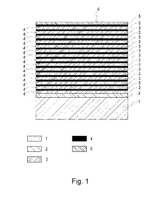
Fig. 1 shows a sample layer structure with a titanium nitride adhesive
layer 2 on a sub-
strate 1 containing 15 layers each of alternating aluminum titanium nitride
layers
3 and aluminum chromium nitride layers 4 and a titanium nitride top layer 5 in
a
first embodiment;
Fig. 2 shows an abstract calotte grinding, i.e. a top view in which the
individual layers
are visible;
Fig. 3 shows a metallographic comparison of sample layers by means of a
calotte grind-
ing, which were deposited onto a specimen using two different systems;
Fig. 1 shows a sample layer construction with a titanium nitride adhesive
layer 2 on a sub-
strate 1 containing 15 layers each of alternating aluminum titanium nitride
layers 3 and
aluminum chromium nitride layers 4 and a titanium nitride top layer 5 in a
first embodiment,
wherein the titanium nitride adhesive layer 2 is followed directly by an
aluminum titanium
nitride layer 3.
Fig. 2 shows an abstract calotte grinding. In the calotte grinding, a ball
grinds a calotte
(spherical cap) into the surface. If the multilayer structure is ground
through to the sub-
strate, then the substrate is visible in the innermost circle. The sample
layer structures are
visible. First, the substrate 1 has a titanium nitride adhesive layer 2
applied to it, which im-
proves the adhesion between the subsequent layers and the substrate 1. The
titanium ni-
Date Recue/Date Received 2021-11-16
CA 03140796 2021-11-16
12
tride adhesive layer 2 is advantageously followed directly by an aluminum
titanium nitride
layer 3. Then come alternating aluminum titanium nitride layers 3 and aluminum
chromium
nitride layers 4; these layers are deposited 15 times each and finally, a
titanium nitride top
layer 5 is deposited.
Fig. 3 shows the metallographic calotte grindings of two sample layer
structures, which have
been deposited onto a cylindrical test specimen composed of the corresponding
steel materi-
al. The layer structure is the same as in Fig. 2. The coating system on the
left was applied
using an alpha 400P coating system produced by the applicant and the coating
system on the
right was applied using an alpha 900P coating system produced by the
applicant.
The figures do not depict a sample use of a titanium carbon nitride top layer
instead of a tita-
nium nitride top layer.
The invention will be explained below based on a specific example:
The chemical composition of the layers in the example consists of approx. 45
at% titanium
and approx. 55 at% nitrogen in the titanium nitride, approx. 35 at% aluminum,
approx. 15
at% chromium, and approx. 50 at% nitrogen in the aluminum chromium nitride,
whereas
approx. 11 at% aluminum, 35 at% titanium, and 45 at% nitrogen are contained in
the alumi-
num titanium nitride.
A coating for cold forming tools is produced in the form of a multilayer hard
material coating,
which, starting from the substrate 1 (tool base material, metal material) and
using PVD-ARC
technology, is deposited as a sequence of a TIN adhesive layer 2, an AlTiN-
AlCrN multilayer
system (15 individual layers), and a TIN top layer 5 and is able to improve
the service life of
the cold forming tool. The optimization of the tool service life is achieved
in that the PVD arc-
based AlTiN-AlCrN multilayer system, because of its mechanical and thermal
properties, pro-
duces wear-minimizing and local thermal effects with respect to the extreme
contact stresses
in the normal direction during forming. The additional thin TIN top layer 5
benefits the break-
Date Recue/Date Received 2021-11-16
CA 03140796 2021-11-16
13
in behavior of the layer and reduces the friction in comparison to the
underlying harder AlTiN-
AlCrN multilayer structure.
The 0.5 pm-thick TIN adhesive layer 2 is deposited with an increasing
substrate temperature
ramp from 400 to 450 C, a decreasing substrate bias voltage of 600 ¨ 220 V,
and a vaporizer
current of 60 A with the aid of the reaction gas N2 at 1.2*10-2 mbar. The
composition of the
TIN adhesive layer 2 is as follows, within the measurement uncertainty: 45 at%
Ti and 55
at% Al.
The 0.2 to 0.3 pm-thick AlTiN layer 3 of the AlTiN-AlCrN multilayer system
starts with an Al-
TIN layer with a high Ti concentration, which is deposited at a substrate
temperature of 450 C
and a substrate bias voltage of 200 V, with a simultaneous deposition of AlTi
cathodes at 55 A
and Ti cathodes at 60 A with the aid of the reaction gas N2 at 2*10-2 mbar.
The composition
of the AlTiN individual layer is as follows, within the measurement
uncertainty: 11 at% Al, 35
at% Ti, and 54 at% N.
The overlying 0.2 to 0.3 pm-thick AlCrN layer 4 of the AlTiN-AlCrN multilayer
system is depos-
ited at a substrate temperature of 450 C, a substrate bias voltage of 80 V,
and an AlCr cath-
ode current of 105 A with the aid of the reaction gas N2 at 2*10-2 mbar. The
composition of
the AlCrN individual layer 4 is as follows, within the measurement
uncertainty: 35 at% Al, 15
at% Ti, and 50 at% N.
The individual layers of AlTiN 3 and AlCrN 4 are applied 15 times one after
another and pro-
duce the above-mentioned AlTiN-AlCrN multilayer system.
The 0.2 pm-thick TIN top layer 5 is deposited with an increasing substrate
temperature of
450 C, a substrate bias voltage of 80 V, and a Ti cathode current of 60 A with
the aid of the
reaction gas N2 at 2*10-2mbar. The composition of the TIN top layer 5 is as
follows, within the
measurement uncertainty: 45 at% Ti and 55 at% Al.
Date Recue/Date Received 2021-11-16
CA 03140796 2021-11-16
14
The layer thickness of the overall layer composite in the example is 5 ¨ 7 pm.
The forming
surface 6 is the tool surface that is oriented toward the workpiece.
The layer properties relating to tool service life were determined on a
stamping tool since
.. stamping tests and the parameters associated with them are better defined
than forming
tests. All of the stamping tests were performed on an eccentric press (four
pillar eccentric
press, 15,000 kg). A respective stamping tool was coated that was made of cold
work steel
(with 0.7 wt% carbon, 5 wt% chromium, 2.3 wt% Mo, 0.5 wt% vanadium, and 0.5
wt%
manganese, 0.2 wt% Si, with a hardness of 60 to 61 HRc). It was used to stamp
a 1.5 mm-
thick sheet composed of super-high-strength steel with a tensile strength of
1400 MPa with-
out additional lubrication.
Stamping parameters:
Stroke rate: 160-170 strokes/minute
.. Feed rate (with 1.5 mm-thick steel sheet): 8 m/min
Pressure: 72,500-74,000 N
The service life was measured in comparison to an aluminum titanium nitride-
based reference
layer and tool failure or the burr height on the stamped workpiece/component
was used as an
.. abort criterion. In other words, if tool failure occurs, then the wear in
the edge regions of the
tool is high enough that a critical burr height is reached on the
workpiece/steel sheet. In this
case, the aluminum titanium nitride-based reference layer reached a critical
burr height at
65,000 strokes and the tool that is coated according to the invention reached
the critical burr
height only after 365,000 strokes. This corresponds to extending the service
life by a factor of
5.
Instead of the TIN top layer, it is also possible to use a TiCN top layer. The
0.2 pm-thick TiCN
top layer can be deposited with an increasing substrate temperature of 450 C,
a falling sub-
strate bias voltage from 150 V to 50 V, and a falling Ti cathode current from
60 A to 42 A with
.. the aid of the reaction gases N2 and CH4at 1.2*10-2 mbar. The composition
of the TiCN top
Date Recue/Date Received 2021-11-16
CA 03140796 2021-11-16
layer is as follows, within the measurement uncertainty: 20 to 23 at% C, 30 -
33 atomic per-
cent N2, and 44 ¨ 50 at% Ti.
With the invention, it has been advantageously possible to significantly
increase the service
5 life of a tool with the multilayer structure according to the invention.
Date Recue/Date Received 2021-11-16
CA 03140796 2021-11-16
16
Reference Numeral List
1 metal material, substrate (tool to be coated)
2 titanium nitride adhesive layer (TIN adhesive layer)
3 aluminum titanium nitride layers (AlTiN layer)
4 aluminum chromium nitride layers (AlCrN layer)
5 titanium nitride top layer (TIN top layer)
6 forming surface
Date Recue/Date Received 2021-11-16