Note: Descriptions are shown in the official language in which they were submitted.
CA 03141200 2021-11-18
WO 2020/239265 PCT/EP2020/025249
1
DESCRIPTION
INTEGRATED MOTOR-COMPRESSOR WITH A STAND-ALONE
MOTOR AND BUNDLE
Embodiments of the invention relate generally to motor
compressor units, and more particularly to a coupling of a compressor
bundle and a motor casing of an integrated in line compressor ("ICL").
Embodiments of the invention also relate to a method for
assembling such a motor compressor unit.
Generally, a motor compressor unit comprises a compressor
bundle mounted in a cylindrical compressor casing and a cylindrical
motor casing.
To assemble the motor compressor unit, the compressor casing
and the motor casing are fastened together forming a housing sealed
tight against a gas to be compressed.
Then, a coupling device is mounted into the housing to connect
a motor shaft and a shaft of the compressor bundle together.
As the two casings are fastened together, generally at least one
small access port is provided in the compressor casing, this port being
sized so that an operator is able to connect each shaft to the coupling
device through the access port, and sized to resist to high pressures
arising in the ICL housing.
After coupling of the two shafts, the access port is hermetically
closed with a hatch so that the compressed gas cannot leak outside the
compressor casing.
The hatch is massive to resist to high pressures.
The access port is also used for maintenance access.
One common used solution to staunch the hatch is to provide
the compressor casing with a plane, the access port been localized on
the plane so that the hatch sealing joints are planar.
However, creating a plane on a cylinder reduces the compressor
casing volume.
CA 03141200 2021-11-18
WO 2020/239265 PCT/EP2020/025249
2
For compressor units comprising a compressor casing with a
small external diameter, the size of the access port may be not large
enough to perform the coupling of the two shafts through the access
port.
The document US 2010/0044966 discloses a motor compressor
unit comprising a compressor casing and a motor casing connected
together with a coupling including access ports.
The motor compressor unit further comprises a coupling guard
comprising sealing members and mounted on two slide guides so that
the coupling guard translates and forms a sealing surface over the
coupling.
However, the coupling guard and slide guides are massive and
voluminous parts.
Moreover, the translation of the coupling guard deteriorates the
sealing members scraping on the motor casing.
There is a need to avoid at least some of the previously-
mentioned drawbacks, especially by suppressing hatches closing
access ports or coupling.
According to an aspect, a compressor bundle for a motor
compressor unit is proposed.
The compressor bundle may include at least one fastening
device configured to fasten the compressor bundle to a motor casing of
the motor compressor unit, and may also include at least one opening
sized to couple of a motor rotor and a compressor rotor through the at
least one opening.
According to another aspect, a motor compressor unit is
proposed.
The motor compressor unit may comprise:
- a compressor bundle as defined above ; and
- a motor casing, the at least one fastening device fastening the
compressor bundle and the motor casing together.
Advantageously, the at least one fastening device is at least
one removable fastening device.
CA 03141200 2021-11-18
WO 2020/239265 PCT/EP2020/025249
3
The motor compressor unit may further comprise a compressor
casing, the compressor bundle being mounted in the compressor casing
fastened to the motor casing, the motor casing and the compressor
casing forming a housing sealed with respect to a gas to be
compressed.
Advantageously, the compressor bundle is fastened in the
compressor casing by at least one removable fastening device.
According to an aspect, a method for assembling a motor
compressor unit is proposed.
The method may comprise:
- fastening a compressor bundle to a motor casing; and
- coupling through at least one opening of the compressor
bundle a motor rotor and a compressor bundle rotor.
A coupling device may be connected to one of the motor rotor
and the compressor rotor, the coupling step comprises connecting the
coupling device to the other rotor.
The method further may further comprise:
- inserting the compressor bundle into a compressor casing; and
- fastening the compressor bundle in the compressor casing, the
motor casing and the compressor casing forming an housing sealed
with respect to a gas to be compressed.
The compressor bundle and the motor casing may be fastened
together by at least one removable fastening device.
The compressor bundle may further be fastened in the
compressor casing by at least one removable fastening device.
The method may further comprise performing at least one
electrical or mechanical connection through the at least one opening.
Other advantages and features of the invention will appear on
examination of the detailed description of embodiments, in no way
restrictive, and the appended drawings in which:
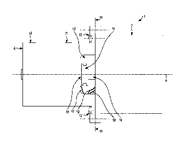
[Fig 1] represents an embodiment of a motor compressor unit;
[Fig 2] illustrates the motor compressor unit without the
compressor casing;
[Fig 3] illustrates a view of the compressor bundle;
CA 03141200 2021-11-18
WO 2020/239265 PCT/EP2020/025249
4
[Fig 4] illustrates a longitudinal cross section of the motor
compressor unit; and
[Fig 5] illustrates an example of a method for assembling the
motor compressor unit.
Embodiments herein disclosed are intend to fasten a
compressor bundle unit and a motor casing in such a way that the
connection of a motor rotor and a compressor bundle rotor is
performed before the compressor bundle unit is inserted into a
compressor casing, the motor casing compressing the compressor
bundle unit and the motor casing forming the motor compressor.
Access ports and hatches usually used to connect the motor
rotor and the compressor bundle rotor are suppressed reducing the
weight of the motor compressor unit, enhancing the sealing integrity
of the motor compressor housing and avoiding that the volume inside
the housing is reduce.
Furthermore, using removable fastening devices to fasten the
compressor bundle to the compressor casing and to fasten the motor
casing to the compressor casing allows to easily extract the
compressor bundle from the compressing casing.
In addition, using removable fastening devices to fasten the
compressor bundle to the motor casing allows to easily dismount the
compressor bundle and the motor casing when the compressor bundle
lies outside the compressor casing.
Reference is made to figure 1 which represents an embodiment
of a motor compressor unit 1 comprising a compressor casing 2, a
motor casing 3 and a central axis A confused with an axis of rotation
of the motor compressor unit.
The casings 2 and 3 are cylindrical.
In another embodiment, the casings 2 and 3 may have another
shape, for example square.
The compressor casing 2 may include a first 4 flange and a
second 5 flange, that are configured to be connected to gas processing
means (not represented).
CA 03141200 2021-11-18
WO 2020/239265 PCT/EP2020/025249
Illustratively, Figure 1 depicts first flange 4 connected with a
gas inlet pipe and the second flange 5 connected with a gas outlet
pipe.
The gas inlet pipe provides a gas to be compressed by the
5 motor compressor unit 1.
The flanges 4 and 5 are arranged perpendicularly to the central
axis A.
In another embodiment, the compressor casing 2 may have
more than two flanges, for example the compressor casing 2 may have
one input flange and two output flanges.
A compressor bundle 6 is mounted in the compressor casing 2.
The compressor bundle 6 may be fastened in the compressor
casing 2 by at least one first removable fastening device 40, for
example screw and thread assemblies so that the compressor bundle 6
can be easily dismounted from the compressor casing 2.
In another embodiment, the compressor bundle 6 is fastened in
the compressor casing 2 without using a removable fastening device.
For example, the two casings may be welded together.
Second fastening devices 7 fasten the compressor casing 2 and
a motor casing 3 together.
The second fastening devices 7 are for example removable
fastening devices comprising screws 8 mounted in threads 9 localized
in the compressor casing 2.
The motor casing and the compressor casing form a housing
sealed tight with respect to the gas to be compressed.
Figure 2 illustrates the motor compressor unit 1 when the
compressor casing 2 is dismounted.
The compressor bundle 6 further comprises a compressor
bundle inlet 10 and a compressor bundle outlet 11 respectively
cooperating with the first flange 4 and the second flange 5 so that gas
flows through the compressor bundle 6.
Third fastening devices 12 fasten the motor casing 3 and the
compressor bundle 6 together.
CA 03141200 2021-11-18
WO 2020/239265 PCT/EP2020/025249
6
The third fastening devices 12 are removable fastening devices
comprising for example screw and thread assemblies.
In another embodiment, the third fastening devices 12 do not
comprise removable fastening means. For example, the motor casing 3
and the compressor bundle 6 are welded together.
The compressor bundle further comprises openings 13 sized for
carry out the coupling of a motor rotor 14 of the motor casing 3 and a
compressor rotor 15 of the compressor bundle 6 through the openings
13.
A coupling device 16 connects the two rotors 14 and 15
together.
The coupling device 16 may be a flexible coupling device to
decouple the two rotors 14 and 15.
The openings 13 are further used to perform electrical or
mechanical connections through the openings 11, for example coupling
wires 17, 18 and 19 to a control circuit 20 (represented on figure 4).
Figure 3 illustrates a view of the compressor bundle 6
according the direction of figure 2.
The compressor bundle 6 comprises three openings 13 regularly
arranged on an outer periphery of the compressor bundle 6.
According to another embodiment, the compressor bundle 6
comprises at least one opening or more openings arranged irregularly
on an outer periphery of the compressor bundle 6, the openings having
a same shape or different shapes.
Figure 4 illustrates a longitudinal cross section of the motor
compressor unit 1.
The motor casing 3 comprises a motor 21 comprising the rotor
14.
The motor 21 may be an electric motor such as a permanent
magnet motor having permanent magnets mounted on the rotor and a
stator. As an alternative, other types of electric motors, such as for
example synchronous, induction, brushed DC motors may be used.
Wire 18 connects the motor 21 to the control circuit 20.
CA 03141200 2021-11-18
WO 2020/239265 PCT/EP2020/025249
7
The motor rotor 14 comprises a motor shaft 14a rotationally
supported in the motor casing 3 by two bearings 22, 23.
The compressor bundle 6 comprises one compression section
comprising four compression wheels 24, 25, 26, 27 mounted on a
compressor shaft 15a, the compression wheels and compressor shaft
15a forming the rotor 15.
The compressor shaft 15a is rotationally supported in the
compressor bundle 6 by two bearings 28, 29.
Bearings 22, 23, 28 and 29 are active magnetic bearings, the
bearings 22 and 23 been connected to the control circuit 20 by the wire
19 and the bearings 28 and 29 been connected to the control circuit 20
by the wire 17.
The control circuit 20 is configured to control the bearings 22,
23, 28 and 29, and the motor 21. The control circuit 20 comprises for
example a microprocessor.
Alternatively, the bearings 22, 23, 28 and 29 may be
hydrodynamic bearings.
In another embodiment, the compressor bundle 6 may comprise
more than one compression section, each section comprising at least
one compression wheel.
In another embodiment, the motor casing 3 and the compressor
bundle 6 comprise more or less than two bearings.
Referring now to Figures 1, 2, 3, and 4, a complete operating
cycle of the compressor is described.
In an embodiment of operation of the motor-compressor unit 1,
the motor 21 rotates the motor rotor 14 and thereby drives the
compressor shaft 15a. A process gas to be compressed is introduced
via the first flange 4 provided in the compressor housing 2. The motor
compressor unit 1 then compresses the process gas through the
compression wheels 24, 25, 26, 27 to thereby produce a compressed
process gas. The compressed process gas then exits the motor
compressor unit 1 via the second flange 5 provided in the compressor
housing 2.
CA 03141200 2021-11-18
WO 2020/239265 PCT/EP2020/025249
8
Figure 5 illustrates an example of a method for assembling the
motor compressor unit 1.
It is assumed that a first end of the coupling device 16 is
connected to the motor shaft 14a and that one end of the wires 18, 17
and 19 is connected to the motor 21, to the bearings 22 and 23, and to
the bearings 28 and 29.
At step 30, the motor casing 3 and the compressor bundle 6 are
fastened together using the third fastening devices 12.
Then, at step 31, the motor rotor 14 and the compressor rotor
15 are coupled together. The second end of the coupling device 16 is
connected to the compressor shaft 15a, a central axis of the axis 14
and 15 been aligned on the central axis A of the motor compressor unit
1.
The coupling is performed through the openings 13.
Further, the free end of the wires 17, 18 and 19 is connected to
the control circuit 20. The connection of the wires 17, 18 and 19 is
performed through the openings 13.
Other electrical connections can be performed through the
openings, for example connecting sensors to the control circuit 20.
Mechanical connections can also be performed through the openings
13 at step 32.
Then, in a stage 32, the compressing bundle 6 fastened to the
motor casing 3 is inserted into the compressor casing 2 and fastened in
the compressor casing 2 by the first fastening device 40.
The compressor casing 2 and motor casing 3 are then fastened
together by the second fastening devices 7 (step 33).
Fastening the compressor bundle 6 to the motor casing 3, and
providing the compressor bundle 6 with at least one opening 13 enable
to couple the motor rotor 14 and compressor rotor 15, and to perform
electrical or mechanical connections without using access ports and
hatches.
The suppression of access ports and hatches reduces the weight
of the motor compressor 1 and enhances the sealing integrity of the
motor compressor housing.
CA 03141200 2021-11-18
WO 2020/239265 PCT/EP2020/025249
9
In addition, the volume inside the housing is not reduced, no
plane surface is required on the housing.
It is very well adapted for motor compressor with small
external diameter.
Furthermore, the use of first 40 and second 7 removable
fastenings devices allows to easily extract the compressor bundle 6
from the compressing casing 2, for example for maintenance
operations, without dismounting the first and second flanges 4, 5
arranged perpendicularly to the central axis A of the motor compressor
1.
In addition, the use of third removable fastening devices 12
enables to easily dismount the compressor bundle 6 and the motor
casing 3 when the compressor bundle 6 lies outside the compressor
casing 4 to ease maintenance operations.
Various inventive aspects of the invention are set forth in the
following clauses, which may be combined in any suitable fashion
unless otherwise indicated:
A. Compressor bundle (6) for a motor compressor unit (1), the
compressor bundle includes at least one fastening device (12)
configured to fasten the compressor bundle to a motor casing (3) of the
motor compressor unit, and also includes at least one opening (13)
sized to couple a motor rotor (14) and a compressor rotor (15) through
the at least one opening.
B. Motor compressor unit (1) comprising:
- a compressor bundle (6) according to A ; and
- a motor casing (3), the at least one fastening device (12)
fastening the compressor bundle and the motor casing together.
C. Motor compressor unit according to B, in which the at least
one fastening device (12) is at least one removable fastening device.
D. Motor compressor unit according to B or C, further
comprising a compressor casing (2), the compressor bundle (6) being
mounted in the compressor casing fastened to the motor casing, the
motor casing and the compressor casing forming a housing sealed with
respect to a gas to be compressed.
CA 03141200 2021-11-18
WO 2020/239265 PCT/EP2020/025249
E. Motor compressor unit according to D, in which the
compressor bundle (6) is fastened in the compressor casing (2) by at
least one removable fastening device (40).
F. Method for assembling a motor compressor unit (1), the
5 method comprises:
- fastening a compressor bundle (6) to a motor casing (3); and
- coupling through at least one opening (13) of the compressor
bundle a motor rotor (14) and a compressor bundle rotor (15).
G. Method according to F, in which a coupling device (16) is
10 connected to one of the motor rotor (14) and the compressor rotor
(15), the coupling step comprising connecting the coupling device to
the other rotor.
H. Method according to F or G, further comprising:
- inserting the compressor bundle (6) into a compressor casing
(2); and
- fastening the compressor bundle in the compressor casing, the
motor casing (3) and the compressor casing forming an housing sealed
with respect to a gas to be compressed.
I. Method according to any one of F, G or H, in which the
compressor bundle (6) and the motor casing (3) are fastened together
by at least one removable fastening device (12).
J. Method according to any one of F, G, H or I, in which the
compressor bundle (6) is fastened in the compressor casing (2) by at
least one removable fastening device (40).
K. Method according to any one of F, G, H, I or J, further
comprising performing at least one electrical or mechanical connection
through the at least one opening (13).