Note: Descriptions are shown in the official language in which they were submitted.
CA 03141237 2021-11-18
WO 2020/260934
PCT/IB2019/055532
TRIANGULATION-BASED OPTICAL PROFILOMETRY SYSTEM
TECHNICAL FIELD
[01] The present application relates to triangulation-based optical
profilometry systems.
BACKGROUND
[02] Triangulation-based three-dimensional optical profilometry systems are
employed as
contact-less surface measurement/mapping systems. A projection system projects
a
luminous line onto a sample surface. An imaging system, disposed at an angle
to the sample
surface, images the projected line onto an image sensor. Based on standard
principles of
triangulation-based profilometry, distortions in the imaged line are used to
calculate the
surface profile along the portion of the sample surface over which the
luminous line was
projected.
[03] Generally, a centerline of the imaged luminous line is used to determine
the surface
profile for the sample surface. Various methods can be used for computing the
centerline of
the imaged luminous line, one of the most popular being the computation of the
centroid
(also referred to as the first moment, center of mass, or center of gravity)
of the brightness
(irradiance) profile along the thickness of the imaged line. The centroid is
then computed
for each sampling position along the imaged line to generate the centerline.
[04] In the interest of maximizing accuracy of the profilometry measurements,
the
projected luminous line is preferably thin, in order to capture a smaller
cross-sectional area
orthogonal to the lateral extent of the line (i.e. thickness of the line).
Similarly, resolution of
the imaging system is often optimized in order to better capture sample
surface details
across a lateral extent of the sample.
[05] However, the fine resolution of triangulation-based profilometry systems
that use
pixel-based image sensors can lead to non-physical artifacts appearing in the
centroid
calculation, and therefore in the calculated surface profile.
[06] Figure 1 depicts an example image 40 of a luminous line projected onto a
flat, tilted
surface, as captured by a two-dimensional pixel array based image sensor. As
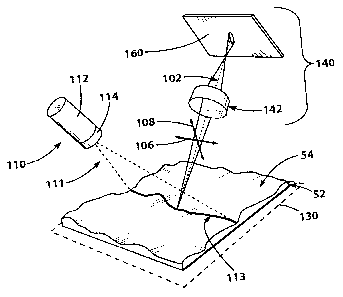
the irradiance
tracks diagonally across the image 40, activation of different rows of pixels
can been seen
1
CA 03141237 2021-11-18
WO 2020/260934
PCT/IB2019/055532
as one moves from left to right. A centroid line 46 extracted from the image
of Figure 1 is
illustrated in graph 45 of Figure 2. A straight line 48, representing the
theoretical centroid
profile associated to a luminous line that would hit a flat, tilted surface is
also illustrated, for
comparison.
[07] As can be seen from the centroid line 46, several jumps or "wiggles" in
the
calculated vertical positions of the centroid are present. These non-physical
artifacts appear
in the centroid calculation where the tilted irradiance line is only detected
in one pixel row
for several adjacent lateral points on the line, due to the thickness of the
imaged line that is
smaller than the vertical dimension of a pixel of the image sensor. Rather
than diagonally
crossing different pixels, some portions of the tilted image line remain
within a single row
of pixels. For instance, in three neighboring pixels, the imaged line could be
incident on a
top portion of the first pixel, a center portion of the second pixel, and a
bottom portion of
the third pixel. In the centroid calculation, however, the image could appear
as a horizontal
line as pixels do not generally report where on a given pixel the light is
detected.
[08] Some solutions have been proposed to address this issue. The
discretization problem
above can at least nominally be tackled by extending the imaged line over many
pixels. One
possible solution is thus simply to use an image sensor with higher resolution
(smaller
pixels), but the increased cost of high-resolution sensors can quickly become
a limiting
factor in such a solution. Depending on the particular system, it is also
possible that no
greater resolution image sensor is available or practical.
[09] It has also been proposed to form a thicker luminous line on the sample
surface
under inspection. The corresponding image line formed on the image sensor will
generally
be thicker, and thus will cover a larger number of pixels along the vertical
direction, aiding
in diminishing this discretization problem. The thicker luminous line formed
on the sample
surface also results in decreased resolution along the direction orthogonal to
the line,
however the sampling area would increase as wider strips of the sample surface
are gathered
into the same line measurement.
[10] In order to cover multiple pixels, defocusing the image of the projected
line has also
been proposed. In such a case, any point of the luminous line formed on the
sample surface
would be imaged over a plurality of pixels of the image sensor. This proposed
solution
would aid in maintaining a small sampling area by keeping a fine line
projected on the
2
CA 03141237 2021-11-18
WO 2020/260934
PCT/IB2019/055532
sample surface. The lateral resolution would however be decreased, as each
point along the
line would be spread laterally across the image sensor as well, overlapping
with adjacent
lateral points along the line.
[11] There therefore remains a desire for solutions related to addressing
measurement
artifacts in triangulation-based three-dimensional optical profilometry
systems.
SUMMARY
[12] It is an object of the present technology to ameliorate at least some
of the
inconveniences present in the prior art. Developers of the present technology
have
developed various embodiments thereof based on their appreciation of at least
one technical
problem associated with the prior art approaches to triangulation-based three-
dimensional
optical profilometry and, particularly, to measurement artifacts related to
imaging resolution
for surface measurement.
[13] In order to aid in minimizing the non-physical artifacts (jumps or
"wiggles") in the
calculated surface profile related to discretization issues in pixel-based
image sensors, an
optical profilometry system is presented herein with the following features in
accordance
with a first broad aspect of the present technology. An objective lens
assembly is arranged
to form an out-of-focus image of a sample plane on an image sensor. The system
further
includes a diaphragm with a non-circular aperture, disposed along an optical
axis between
the sample plane and the image sensor. The defocused image of a luminous line
projected
on the sample plane is then asymmetrically spread over the image sensor. The
image of any
given point along the luminous line is thus received at the image sensor as a
defocused spot,
elongated along a vertical direction to extend over a greater number of pixels
of the image
sensor in the vertical direction than in the lateral direction. The vertical
centroid of the
imaged line can then be calculated over multiple rows of pixels, diminishing
the effect of
the discrete pixel arrangement. As the defocus is less extensive along the
lateral direction,
aiding in maintaining the lateral resolution of the measurement.
[14] In accordance with one broad aspect of the present technology, there
is provided
triangulation-based optical profilometry system for scanning a three-
dimensional sample
surface located at a sample plane of the system. The system includes a
projection system for
3
CA 03141237 2021-11-18
WO 2020/260934
PCT/IB2019/055532
projecting a luminous line across the sample surface; an image sensor for
converting images
of the luminous line, as projected on the sample plane, into electrical
signals; a processing
unit communicatively connected to the image sensor for processing the
electrical signals; an
objective lens assembly for imaging the luminous line, as projected on the
sample plane,
onto the image sensor, the objective lens assembly defining an optical axis
extending
between the sample plane and the image sensor, a first direction orthogonal to
the optical
axis and being defined parallel to an extent of the luminous line as
projected, a second
direction being defined perpendicular to the first direction, the first and
second directions
defining a plane orthogonal to the optical axis; and a diaphragm disposed
along the optical
axis between the sample plane and the image sensor, the diaphragm defining a
non-circular
aperture therein, the aperture being defined by a first dimension and a second
dimension
perpendicular to the first dimension, the second dimension being greater than
the first
dimension, the diaphragm being rotationally oriented relative to the image
sensor such that
the first dimension is aligned with the first direction and the second
dimension is aligned
with the second direction, the objective lens assembly being arranged to form
an out-of-
focus image of the sample plane on the image sensor.
[15] In some embodiments, the diaphragm, the objective lens assembly and
the image
sensor are arranged such that an image of a given point along the luminous
line, as projected
onto the sample surface and collected by the image sensor during operation of
the system,
exhibits greater defocus along the second direction than the first direction.
[16] In some embodiments, the luminous line extends laterally across the
sample
plane; the first direction is a lateral direction; the second direction is a
vertical direction; and
the diaphragm, the objective lens assembly, and the image sensor are arranged
such that an
image of a given point along the luminous line, as projected onto the sample
surface and
.. collected by the image sensor during operation of the system, exhibits
greater vertical
defocus than lateral defocus.
[17] In some embodiments, the image sensor is a two-dimensional array of
pixels; and
during operation of the system, the image of the given point of the luminous
line extends
over a greater number of pixels of the image sensor in the vertical direction
than in the
lateral direction.
[18] In some embodiments, during operation of the system, the image of the
given point
4
CA 03141237 2021-11-18
WO 2020/260934
PCT/IB2019/055532
of the luminous line on the image sensor extends vertically over at least two
pixels of the
image sensor.
[19] In some embodiments, a normal defined by the sample plane is skewed by a
first
angle (y) relative to the optical axis; and a normal defined by the image
sensor is skewed by
a second angle (y') relative to the optical axis.
[20] In some embodiments, the first angle (y) and the second angle (y') are
arranged in a
Scheimpflug configuration, such that the second angle (y') is chosen relative
to the first
angle (y) according to the relation: y' = tan-1
tan(y)1, where S, is an image distance
so
measured from the objective lens assembly to the image sensor and So is an
object distance
measured from the sample plane to the objective lens assembly.
[21] In some embodiments, the projection system includes at least one
illumination
source; and a projection optical assembly for projecting light from the
illumination source
onto the sample plane in the form of a line.
[22] In some embodiments, the at least one illumination source is a laser
source; and the
luminous line is a laser line projected onto the sample plane.
[23] In some embodiments, the image sensor is disposed at a defocus position
shifted
along the optical axis away from an image plane of the sample plane as imaged
by the
objective lens assembly.
[24] In some embodiments, the objective lens assembly includes a plurality of
lenses.
[25] In some embodiments, the diaphragm is disposed at an aperture stop of the
objective
lens assembly.
[26] In some embodiments, the diaphragm is disposed at an entrance pupil of
the
objective lens assembly.
[27] In some embodiments, the diaphragm is disposed at an exit pupil of the
objective
lens assembly.
[28] In some embodiments, the second dimension of the aperture is about four
times
greater than the first dimension.
5
CA 03141237 2021-11-18
WO 2020/260934
PCT/IB2019/055532
[29] In some embodiments, the aperture is generally rectangular in form.
[30] In some embodiments, a shape of the aperture is one of a geometric
stadium, an
oval, a rhombus, and a rounded-corner rectangle.
[31] In some embodiments, the image sensor is one of: a charge-coupled device
(CCD), a
complementary metal¨oxide¨semiconductor (CMOS) device, and a N-type metal-
oxide-
semiconductor (NMOS) device.
[32] Quantities or values recited herein are meant to refer to the actual
given value. The
term "about" is used herein to refer to the approximation to such given value
that would
reasonably be inferred based on the ordinary skill in the art, including
equivalents and
approximations due to the experimental and/or measurement conditions for such
given
value.
[33] For purposes of this application, terms related to spatial orientation
such as vertical
and lateral are as they would normally be understood with reference to an
optical axis to
which the vertical and lateral directions are orthogonal. Terms related to
spatial orientation
when describing or referring to components or sub-assemblies of the system,
separately
from the system, should be understood as they would be understood when these
components
or sub-assemblies are assembled in the system, unless specified otherwise in
this
application.
[34] In the context of the present specification, unless expressly provided
otherwise, a
"computer" and a "processing unit" are any hardware and/or software
appropriate to the
relevant task at hand. Thus, some non-limiting examples of hardware and/or
software
include computers (servers, desktops, laptops, netbooks, etc.), smartphones,
tablets, network
equipment (routers, switches, gateways, etc.) and/or combination thereof.
[35] Embodiments of the present technology each have at least one of the above-
mentioned object and/or aspects, but do not necessarily have all of them. It
should be
understood that some aspects of the present technology that have resulted from
attempting
to attain the above-mentioned object may not satisfy this object and/or may
satisfy other
objects not specifically recited herein.
[36] Additional and/or alternative features, aspects and advantages of
implementations of
6
CA 03141237 2021-11-18
WO 2020/260934
PCT/IB2019/055532
the present technology will become apparent from the following description,
the
accompanying drawings and the appended claims.
BRIEF DESCRIPTION OF THE DRAWINGS
[37] For a better understanding of the present technology, as well as other
aspects and
further features thereof, reference is made to the following description which
is to be used
in conjunction with the accompanying drawings, where:
[38] Figure 1 depicts an example image of a projected line as captured by a
triangulation
based three-dimensional optical profilometry system according to the prior
art;
.. [39] Figure 2 illustrates a surface profile determined from the imaged line
of Figure 1;
[40] Figure 3 schematically depicts a triangulation-based three-dimensional
optical
profilometry system according to the present technology;
[41] Figure 4 is a close-up view of some portions of the profilometry system
of Figure 3;
[42] Figure 5A is an example line as imaged by the profilometry system of
Figure 3;
[43] Figure 5B illustrates a surface profile determined from the imaged line
of Figure 5A;
[44] Figure 6 schematically depicts a side view of an objective lens assembly
and
diaphragm of the profilometry system of Figure 3, the Figure further showing
three
particular positions of the diaphragm along an optical axis;
[45] Figure 7 illustrates the diaphragm of Figure 6, as viewed along the
optical axis of the
objective lens assembly of Figure 6;
[46] Figures 8 to 11 illustrate different alternative embodiments of the
diaphragm of
Figure 7; and
[47] Figure 12 schematically depicts the relative arrangement of some
components of the
profilometry system of Figure 3.
[48] The drawings are not necessarily to scale and may be illustrated by
phantom lines,
diagrammatic representations and fragmentary views. In certain instances,
details that are
7
CA 03141237 2021-11-18
WO 2020/260934
PCT/IB2019/055532
not necessary for an understanding of the embodiments or that render other
details difficult
to perceive may have been omitted. It should further be noted that throughout
the appended
drawings, like features are identified by like reference numerals.
DETAILED DESCRIPTION
[49] Reference will now be made in detail to various non-limiting embodiments
for an
optical system and components disposed therein. It should be understood that
other non-
limiting embodiments, modifications and equivalents will be evident to one of
ordinary skill
in the art in view of the non-limiting embodiments disclosed herein and that
these variants
should be considered to be within the scope of the appended claims.
Furthermore, it will be
recognized by one of ordinary skill in the art that certain structural and
operational details of
the non-limiting embodiments discussed hereafter may be modified or omitted
altogether
(i.e. non-essential). In other instances, well known methods, procedures, and
components
have not been described in detail.
[50] A triangulation-based three-dimensional optical profilometry system 100
according
to the present technology, also referred to herein as the system 100, is
schematically
illustrated in Figures 3 and 4. The system 100 includes a projection system
110 for
projecting light onto a sample, a sample plane 130 for receiving the sample,
and an imaging
assembly 140 for imaging part of the light reflected from the illuminated
portion of the
sample surface 54. Each of the projection system 110, the sample plane 130,
and the
imaging assembly 140 will be described in more detail below. Depending on the
specific
embodiment or application, the system 100 could include additional components
that need
not be described herein, including but not limited to: support structures,
mechanical stages,
power supplies, control hardware and/or software, electronic systems, etc.
[51] The general principle of operation of the triangulation-based three-
dimensional
optical profilometry system 100 is illustrated in Figure 3. The projection
system 110
produces a fan-shaped light beam 111 which generates a luminous line 113
spanning across
the sample plane 130 along a lateral direction 106, spanning a lateral extent
of a sample 52
disposed on the sample plane 130. As used herein, it should be noted that the
"lateral"
direction 106 simply indicates a direction orthogonal to a line connecting the
projection
system 110 and the imaging assembly 140 and generally parallel to the sample
plane 130.
8
CA 03141237 2021-11-18
WO 2020/260934
PCT/IB2019/055532
There is not meant to be suggested by the term lateral any specific
orientation in space of
either the system 100 or any sample measured therein.
[52] The luminous line 113, as projected across a sample surface 54 of the
sample 52, is
then imaged by the imaging assembly 140, which includes an objective lens
assembly 142
and an image sensor 160. As is illustrated, for samples 52 which have a
smaller lateral
extent than the luminous line 113, portions of the sample plane 130 may also
be imaged. It
is also contemplated that the projection system 110 could be adjusted to
project only onto
the sample 52.
[53] As imaged by the imaging assembly 140, the line 113 does not generally
appear as a
straight line. Instead, topological features of the sample 52 distort the
luminous line 113, as
seen from the vantage point of the imaging assembly 140. Topological features
of the
sample 52 which can distort the luminous line 113 include, but are not limited
to: surface
shape, curvature, surface steps, surface roughness, irregularities, and holes
or gaps in the
surface. For example, the close-up partial image of a portion of the sample
surface 54 shows
surface roughness which causes the luminous line 113 to appear to undulate.
[54] The imaging assembly 140 then captures one or more images of the luminous
line
113 formed on the sample 52 at a plurality of locations along a length of the
sample 52 (the
length being measured along a direction perpendicular to the lateral extent of
the line 113).
In accordance with the principles of optical trigonometric triangulation, the
objective lens
assembly 142 and the image sensor 160 are located and oriented such that local
variations in
height located on the portion of the sample surface 54 illuminated by the
luminous line 113
are detected by corresponding vertical shifts in images of the luminous line
113. A sample
image 117 is illustrated as having been determined by a processing unit 170
(specifically a
computer 170).
[55] The image 117 is then processed by the computer 170 in order to correlate
the line
of the image 117 to the physical lateral extent and height of the sample
surface 54. For each
individual position along the length of the sample 52, a two-dimensional
graph, illustrated
by sample graph 119, is then created. The horizontal x-axis of the graph 119
corresponds to
the lateral position across the sample and the vertical z-axis is the
determined height, based
on the distortion of the projected straight luminous line 113 by the profile
of the sample
surface 54. The deviations in the image 117 are correlated to an actual height
variation of
9
CA 03141237 2021-11-18
WO 2020/260934
PCT/IB2019/055532
the sample surface 54, as illustrated on the z-axis of the graph 119,
depending on parameters
such as the angles of the projection system 110 and the imaging assembly 140
relative to the
sample plane 130 and the magnification of the objective lens assembly 142. As
is mentioned
above, a centroid of the imaged line along the vertical direction is
calculated for each lateral
position (along the x-axis) to determine the sample surface profile currently
illuminated the
projection system 110. Finally, the process of imaging the luminous line 113
at a particular
position along the length of the sample surface 54 is repeated as the luminous
line 113 is
swept along the length of the sample surface 54. A three-dimensional map of
the profile of
the sample surface 54 can then be created by combining the graphs 119
collected across the
length of the sample surface 54.
[56] In order to aid in minimizing the non-physical artifacts (jumps or
"wiggles") visible
in the calculated surface profile illustrated in the example of Figure 2 and
discussed above,
the objective lens assembly 142 is arranged to form an out-of-focus image of
the sample
plane 130 on the image sensor 160. The system 100 further includes a diaphragm
150 with a
non-circular aperture 154 (see Figure 7, described in more detail below). The
diaphragm
150 is disposed along an optical axis 102 (defined by the objective lens
assembly 142)
between the sample plane 130 and the image sensor 160 such that the defocused
image of
the luminous line 113 is asymmetrically spread over the image sensor 160. As
is illustrated
schematically in Figure 4, the image of any given point along the luminous
line 113 is
received at the image sensor 160 as a defocused spot, elongated along a
vertical direction
108 (perpendicular to the lateral direction 106 of the luminous line 113).
[57] During operation of the system 100, the image of each point of the
luminous line
113 thus extends over a greater number of pixels of the image sensor 160 in
the vertical
direction 108 than in the lateral direction 106. An example image of a
luminous line
projected on a tilted, flat surface is illustrated in Figure 5A, where it can
be seen that the
line is defocused along the vertical direction 108 and activates at least two
pixels along the
entire lateral extent of the line. This allows the vertical centroid of the
imaged line 113 to be
calculated over multiple rows of pixels, diminishing the effect of the
discrete pixel
arrangement as is illustrated in Figure 5B. As the defocus is less extensive
along the lateral
direction 106, the lateral resolution is less affected than it would be in
cases where a
circularly uniform defocus is present. While in the present embodiment the
image of each
given point of the luminous line 113 extends over at least two pixels of the
image sensor
CA 03141237 2021-11-18
WO 2020/260934
PCT/IB2019/055532
160 in the vertical direction 108, it is contemplated that the thickness of
the imaged line 113
could extend over more pixels of the image sensor 160.
[58] While the particulars of any given embodiment could differ, components
employed
in the present embodiment of the system 100 will now be described in more
detail, with
continuing reference to Figures 3 and 4.
[59] The projection system 110 includes an illumination source 112 and a
projection
optical assembly 114 for projecting light from the illumination source 112
onto the sample
plane 130 in the form of a line. In the present embodiment, the illumination
source 112 is a
laser source 112 and the line projected onto the sample plane 130 is a laser
line. It is
contemplated that other light sources, including partially-coherent and
incoherent light
sources, could be used in some embodiments. In some embodiments, it is also
contemplated
that the illumination source 112 could include multiple light sources. For
instance, in some
embodiments the illumination source 112 could include a plurality of laser
sources emitting
at different wavelengths. The projection optical assembly 114 includes a
plurality of lenses
and a linear slit (not separately illustrated), although different assemblies
of optical
components are contemplated.
[60] The projection system 110 projects the luminous line 113 onto the sample
52
disposed on the sample plane 130. The sample plane 130 is the plane where the
sample
surface 54 should be located for proper operation of the system 100. In some
embodiments,
the sample plane 130 could be defined by a sample stage or table for receiving
the sample
52. In some embodiments, the projection system 110 and/or the imaging assembly
140
could be positioned or adjusted such that the sample plane 130 generally
aligns with the
sample surface 54. Depending on the particular light source and arrangement,
it is
contemplated that the luminous line 113 could be well defined at a plurality
of different
planes. In some cases, the luminous line 113 will get its minimum thickness at
one
particular distance from the projection system 110, preferably at the distance
of the sample
plane 130.
[61] The luminous line 113 is then imaged from the sample 52 by the imaging
assembly
140. The imaging assembly 140 includes the image sensor 160, an objective lens
assembly
142 and a diaphragm 150 disposed therein. The objective lens assembly 142 and
the
diaphragm 150 will be described in more detail below.
11
CA 03141237 2021-11-18
WO 2020/260934
PCT/IB2019/055532
[62] The image sensor 160 converts images of the luminous line 113, as
projected on the
sample plane 130 and imaged onto the image sensor 160 by the objective lens
assembly
142, into electrical signals. According to the present technology, the image
sensor 160 is a
two-dimensional array of pixels, specifically a charge-coupled device (CCD).
Depending on
the particular embodiment, it is contemplated that the image sensor 160 could
be embodied
by sensors including, but not limited to, complementary
metal¨oxide¨semiconductor
(CMOS) devices and a N-type metal-oxide-semiconductor (NMOS) device.
[63] The system 100 includes a processing unit 170 communicatively connected
to the
image sensor 160 for processing the electrical signals generated by the image
sensor 160.
The processing unit 170 is generally described as the computer 170 herein, but
this is
simply one example of a non-limiting embodiment. Depending on the particular
embodiment of the system 100, it is contemplated that the processing unit 170
could be
implemented as various structures, including but not limited to: one or more
processors in a
computing apparatus, software supported by a computing apparatus, and
processing boards
(GPU, FPGA, etc.). As is mentioned above, the computer 170 receives the
electrical signals
representing the image of the projected luminous line 113 from the image
sensor 160. Based
on those electrical signals, the computer 170 then calculates the centroid
profile of the
imaged line 113 to determine a physical profile of the sample surface 54.
[64] With further reference to Figures 6 to 11, the objective lens assembly
142 and the
diaphragm 150 will now be described in more detail. As is mentioned briefly
above, the
optical axis 102 is defined by the optical axis of the objective lens assembly
142. As is
noted above, the lateral direction 106 is the direction orthogonal to a line
connecting the
projection system 110 and the imaging assembly 140 and generally parallel to
the sample
plane 130. Generally, the lateral direction 106 is thus also parallel to the
extent of the
luminous line 113 as projected and orthogonal to the optical axis 102. The
vertical direction
108 is defined perpendicular to the lateral direction 106. The vertical and
lateral directions
106, 108 thus generally define a plane orthogonal to the optical axis 102, as
is illustrated in
Figure 4.
[65] The objective lens assembly 142 includes a plurality of lenses 144 in the
illustrated
example of Figure 6, specifically a pair of doublets 144. It should be noted
that this is
simply one non-limiting embodiment according to the present technology. It is
12
CA 03141237 2021-11-18
WO 2020/260934
PCT/IB2019/055532
contemplated that the objective lens assembly 142 could include more lenses
144 than
illustrated, or only a single lens 144 depending on particulars of the
embodiment.
[66] The diaphragm 150 is disposed along the optical axis 102 between the
sample plane
130 and the image sensor 160. In the illustrated embodiment, the diaphragm 150
has been
inserted between the lenses 144 so that the diaphragm 150 is located at an
aperture stop 146
of the objective lens assembly 142. It is contemplated, however, that the
diaphragm 150
could be disposed exterior to the objective lens assembly 142, either on an
object side or an
image side of the objective lens assembly 142. In some embodiments for
example, the
diaphragm 150 could be disposed at an entrance pupil 147 of the objective lens
assembly
142. In some other embodiments, the diaphragm 150 could be disposed at an exit
pupil 149
of the objective lens assembly 142. The particular choice of placement of the
diaphragm
150 along the optical axis 102 could depend on a variety of factors including,
but not
limited to, physical constraints in the objective lens assembly 142 or the
imaging assembly
140 and magnification of the objective lens assembly 142.
[67] It is further contemplated that in some embodiments, the objective lens
assembly
142 could be an off-the-shelf lens assembly adapted for receiving a
commercially-available
diaphragm defining a circular aperture. The diaphragm 150 according to the
present
technology could then be inserted into the off-the-shelf lens assembly, in
place of the round
aperture diaphragm.
[68] As is mentioned above, the diaphragm 150 defines therein a non-circular
aperture
154. In the present embodiment, the aperture 154 is in the shape of a rounded-
corner
rectangle, as shown in Figure 7. Different aperture shapes could be
implemented in the
present technology, as will be described in further detail below.
[69] With reference to Figure 7, the aperture 154 is defined in size by two
dimensions: a
"vertical" dimension 156 and a "lateral" dimension 158 perpendicular to the
vertical
dimension 156. The terms vertical and lateral dimension 156, 158 are used due
to their
alignment in the system 100 with the vertical and lateral directions 108, 106
when the
diaphragm 150 is in use in the system 100. It should be noted however that the
diaphragm
150 could be differently oriented when considered separately from the system
100 without
changing the relative sizing of the "vertical" and the "lateral" dimensions
156, 158.
13
CA 03141237 2021-11-18
WO 2020/260934
PCT/IB2019/055532
[70] By the present technology, the vertical dimension 156 is greater than the
lateral
dimension 158, such that a larger portion of the light incident on the
diaphragm 150 is
allowed to pass the aperture stop 146 in the vertical direction 108 than in
the lateral
direction 106. In the present embodiment, the vertical dimension 156 is about
four times
greater than the lateral dimension 158, but the ratio of the vertical
dimension 156 to the
lateral dimension 158 could be greater or smaller depending on the specific
embodiment.
[71] When assembled in the system, the diaphragm 150 is rotationally oriented
such that
the vertical dimension 156 is aligned with the vertical direction 108 and the
lateral
dimension 158 is aligned with the lateral direction 106. As the objective lens
assembly 142
is arranged to form an out-of-focus image of the sample plane 130 on the image
sensor 160,
the non-circular aperture 154 produces a non-circular spot on the image sensor
160 for any
given point on the luminous line 113. Specifically, the spot on the image
sensor 160 is
generally oval and elongated along the vertical direction 108, although the
exact spot size
and dimensions will vary with the specific embodiment of the diaphragm 150 and
the
objective lens assembly 142.
[72] As is noted above, this combination of the non-circular aperture 154 and
the
objective lens assembly 142 being arranged at a defocus position relative to
the image
sensor 160 allows the imaged line 113 to extend vertically over at least two
rows of pixels
to aid in diminishing the effect of pixel-based artifacts in centroid
calculation of surface
profiles.
[73] In some embodiments, in place of the diaphragm 150 in the form of a
rounded-
corner rectangle, the system 100 could instead include differently shaped
apertures. For
instance, the system 100 could include a diaphragm 250 defining a rhombus-
shaped
aperture 254 (illustrated in Figure 8). In other embodiments, the system 100
could include a
diaphragm 350 defining a geometric stadium-shaped aperture 354, a diaphragm
450
defining a generally rectangular-shaped aperture 454, or a diaphragm 550
defining an oval-
shaped aperture 554 (illustrated in Figures 9 to 11 respectively). In each of
the apertures
254, 354, 454, 554, the vertical dimension of the aperture is about 4 times
the lateral
dimension of the aperture.
[74] As the image sensor 160 and the objective lens assembly 142 are arranged
to create
an out-of-focus image of the sample plane 130, the sample plane 130 and the
image sensor
14
CA 03141237 2021-11-18
WO 2020/260934
PCT/IB2019/055532
160 are further arranged relative to one another in order to maintain a
consistent defocus
across the image plane on the image sensor 160, in order to avoid varying spot
size at
different locations of the image sensor 160. In the present embodiment, the
sample plane
130 and the image sensor 160 are each skewed to the optical axis 102 of the
system 100
according to a Scheimpflug configuration. In Figure 12, the Scheimpflug
configuration of
the sample plane 130 and the image sensor 160 relative to the optical axis 102
is illustrated.
[75] For simplicity of illustration, the objective lens assembly 142 is
schematically
depicted as a single thin lens. As will be generally understood in the art,
distances such as
image distance and object distance are calculated with respect to principal
planes of the
objective lens assembly 142.
[76] According to the Scheimpflug configuration, a normal 131 to the sample
plane 130
is skewed by a first angle (y) relative to the optical axis 102, where a
center of the sample
plane 130 is disposed at an object distance So from the objective lens
assembly 142. A
normal 161 to the plane of the image sensor 160 is then skewed by a second
angle (y')
relative to the optical axis 102, where a center of the image sensor 160 is at
an image
distance S, from the objective lens assembly 142.
[77] The angles (y), (y') between the normals 131, 161 and the optical axis
102 are then
arranged according to the relation:
= tan-1 tan (y)1
so
[78] While the angles (y), (y') are chosen based on known distances S, So in
the example
above, it is contemplated that the angles (y), (y') could be constrained (for
instance
depending on mechanical restrictions on the system 100), and the distances Sõ
So could
instead be adapted based on the constrained angles (y), (y'). It is also
contemplated that
different configurations other than the Scheimpflug configuration could be
utilized to
arrange the components of the system 100.
[79] It is noted that the foregoing has outlined some of the more pertinent
non-limiting
embodiments. It will be clear to those skilled in the art that modifications
to the disclosed
non-limiting embodiments can be effected without departing from the spirit and
scope
thereof. As such, the described non-limiting embodiments ought to be
considered to be
CA 03141237 2021-11-18
WO 2020/260934
PCT/IB2019/055532
merely illustrative of some of the more prominent features and applications.
Other
beneficial results can be realized by applying the non-limiting
implementations in a
different manner or modifying them in ways known to those familiar with the
art.
[80] The mixing and/or matching of features, elements and/or functions between
various
.. non-limiting embodiments are expressly contemplated herein as one of
ordinary skill in the
art would appreciate from this disclosure that features, elements and/or
functions of one
embodiment may be incorporated into another implementation as appropriate,
unless
expressly described otherwise, above. Although the description is made for
particular
arrangements and methods, the intent and concept thereof may be suitable and
applicable to
other arrangements and applications.
16