Note: Descriptions are shown in the official language in which they were submitted.
WO 2020/252587
PCT/CA2020/050851
- 1 -
TRIGGER DEVICE
100011 The present disclosure relates generally to firearms and more
specifically to an
improvement two-stage trigger device. This application claims priority to U.S.
Provisional
Application No. 62/863,633 filed on June 19, 2019, the contents of which are
incorporated by
reference herewith.
BACKGROUND
100021 A firing mechanism is used to actuate the sequence of a firearm or
crossbow by
movement of a trigger. The trigger is generally activated by imposing a
trigger pull load on
the trigger, causing the trigger to move from a loaded position, at which the
firing mechanism
is activatable, to a released position, at which the firing mechanism is
activated. As is well
known, it is desirable for the trigger pull load to be predictable. For
example, firing a firearm
is more accurate if the trigger pull load is consistent for the user.
100031 There are competing factors to be taken into account in determining the
trigger pull
load required to pull the trigger. For example, if the trigger pull load is
relatively large,
inadvertent activation of the firing mechanism is unlikely thereby increasing
safety of the
firearm. On the other hand, if the trigger pull load is relatively small,
activating the firing
mechanism is relatively easy thereby reducing the effect of activating the
trigger on accuracy
of the firearm. Further, a small trigger pull load may increase the frequency
at which the
firearm can be activated.
MOW] For highly accurate target or hunting purposes, the vast majority of
firearm
operators have a preferred trigger pull load. Most known trigger mechanisms
have a spring
bias imparted to the trigger to oppose trigger movement by the operator.
Adjusting the
compression or tension forces in the spring opposing the movement of the
trigger will modify
the force resisting the trigger movement.
100051 Some shooters prefer what is known as a two-
stage trigger. In a first stage, a
first-stage trigger pull load is required to move the trigger to a position
just short of that
required to release the sear and fire the firearm. At the end of the first
stage, the trigger
encounters additional resistance. The additional resistance indicates to the
operator that it
the trigger has entered the second stage and is ready for firing by the
application of a
second stage trigger pull load to the trigger. The extent of the first and
second stage pull
loads is a matter of choice of the firearm operator, although it often has to
be determined in
advance and is set prior to installation of the trigger.
100061 However, two-stage triggers are more complex
than single-stage triggers and
often require additional spacing in the firearm, when space may be limited.
For example,
some known two-stage triggers are not feasible for use with firearms, such as
rifles for
example, due to limited space in the firearm.
CA 03141277 2021-12-9
WO 2020/252587
PCT/CA2020/050851
-2-
100071 Although various attempts have been made to
improve the performance of a
trigger in a firearm, further improvements are desired. It is therefore an
object at least to
provide a novel two-stage trigger device.
SUMMARY
100081 In accordance with an aspect of an embodiment,
there is provided a trigger
device comprising: a housing; a trigger rotatably mounted in the housing via a
trigger pivot
pin, the trigger comprising a trigger tooth; a reverser rotatably mounted in
the housing via a
reverser pivot pin, the reverser comprising a reverser tooth; a first pull
weight adjustment
mechanism coupled between the trigger and the reverser to bias the trigger in
a first
direction and the reverser in an opposite direction; wherein actuation of the
trigger causes
the trigger to rotate in the opposite direction, the trigger tooth to engage
the reverser tooth,
and the reverser to rotate in the first direction.
[0009] The trigger device may further comprise a ticker
rotatably mounted in the housing
via a ticker pivot pin, wherein the ticker is configured to rotate when
pressure applied to of
the trigger is sufficient to overcoming the bias of the first pull weight
adjust mechanism; and
a sear configured to unload when the ticker rotates to a predefined tipping
point
[0010] The trigger device may further comprise a
captured roller positioned between the
ticker and the sear, the captured roller configured to increasingly translate
upon rotation of
the ticker; wherein the tipping point is defined by an amount of translation
of the captured
roller.
[0011] In an embodiment, there may be a recess in the
ticker and a trigger extender on
the trigger, wherein the trigger extender is positioned to abut the ticker
when the trigger is
released and the trigger extender is positioned over the recess when pressure
is applied to
the trigger.
[0012] The trigger device may further comprise a second
pull weight adjustment
mechanism to bias the ticker to maintain the sear in a loaded position. The
ticker rotates to
the predefined tipping point when pressure applied to of the trigger is
sufficient to
overcoming the bias of the first pull weight adjust mechanism and the bias of
the second pull
weight adjust mechanism. The first pull weight may be greater than the second
pull weight
or the second pull weight may be greater than the first pull weight.
[0013] In accordance with another aspect of an
embodiment, there is provided a trigger
device for activating a firing mechanism, the trigger device comprising: a
housing; a trigger
pivotally mounted on the housing via a trigger pivot pin, the trigger
comprising a trigger
extender; a sear pivotally mounted on the housing via a sear pivot pin; and a
ticker pivotally
mounted on the housing via a sear pivot pin, the ticker comprising a recess
and configured
to translate pressure applied to the trigger to the sear to activate the
firing mechanism;
CA 03141277 2021-12-9
WO 2020/252587
PCT/CA2020/050851
- 3 -
wherein the trigger extender is positioned to abut the ticker when the trigger
is released and
the trigger extender is positioned over the recess when pressure is applied to
the trigger.
[0014] The trigger extender may be nestled within the
recess when the sear is unloaded.
The recess may be configured to inhibit the trigger from returning to a ready
position until the
sear is reloaded.
BRIEF DESCRIPTION OF THE DRAWINGS
[0015] Embodiments will now be described by way of
example only with reference to the
accompanying drawings in which:
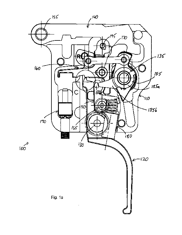
Fig. la is a side view of the trigger device shown in a position in which the
sear is loaded
and the trigger actuation lever is released;
Fig. lb as a cross-sectional view of Fig. la;
Fig. lc is an detailed view of an interface between the trigger and the first
pull weight
adjustment mechanism;
Fig. 2a is a side view of the trigger device shown in a position in which the
sear is loaded
and pressure sufficient to overcome a first stage is applied to the trigger
actuation lever;
Fig. 2b is a cross-sectional view of Fig. 2a;
Fig. 3a is a side view of the trigger device shown in a position in which the
sear is loaded
and pressure sufficient to overcome a second stage is applied to the trigger
actuation lever;
Fig. 3b is a cross-sectional view of Fig. 3a;
Fig. 4 is a side view of the trigger device shown in a position in which the
sear is unloaded
and the trigger actuation lever is released;
Fig. 4b is a cross-sectional view of Fig. 4a; and
Fig. 5 is a graph illustrating the two-stage nature of the trigger.
DETAILED DESCRIPTION OF THE EMBODIMENTS
[0016] For convenience, like numerals in the
description refer to like structures in the
drawings. Referring to Figs. la, lb, and lc, a trigger device for activating a
firing
mechanism of a firearm is illustrated generally by reference numeral 100. The
trigger device
100 comprises a housing 110, a trigger 120, a trigger pivot pin 130, a sear
140, a sear pivot
pin 155, a ticker 160, a ticker pivot pin 170, a captured roller 195, a
reverser 150, a reverser
pivot pin 165, a first pull weight adjustment mechanism 180, a second pull
weight adjustment
mechanism 190, a safety 185, and a safety pivot pin 135.
[0017] The trigger 120 comprises an actuation member
120a, a central portion 120b, a
trigger flat 120c, an trigger extender 120d, and a trigger tooth 120e. The
central portion
120b is rotationally coupled to the trigger pivot pin 130 and comprises the
trigger tooth 120e.
The actuation member 120a generally extends from the central portion 120b such
that it
protrudes from the housing 110. The actuation member 120a is configured to
interface with
CA 03141277 2021-12-9
WO 2020/252587
PCT/CA2020/050851
- 4 -
a finger of an operator of the firearm. In most embodiments the actuation
member 120a will
be arcuate. The trigger flat 120c generally extends from the central portion
120b towards an
interior of the housing 110. The trigger extender 120d is a protrusion or hook
located at a
distal end of the trigger flat 120. The trigger extender 120d extends radially
further from the
central portion 120b than the trigger flat 120c. The trigger 120 further
include a hole 1201,
extending though the actuation member 120a. A plurality of wedge-shaped
protrusions 120g
are positioned around the hole 120f on an upper surface of the actuation
member 120a.
100181 The reverser 150 comprises a main portion 150a,
a reverser flat 150b, a reverser
arm 150c, a reverser nub 150d, and a reverser tooth 150e. The main portion
150a is
rotationally coupled to the reverser pivot pin 165 and comprises the reverser
tooth 150e.
The reverser flat 150b generally extends from the main portion 150a. The
reverser arm
150c extends from a mid-portion of the reverser flat 150b. The reverser nub
150d protrudes
from reverser flat 150b.
100191 The ticker 160 comprises a main portion 160a, a
sear-engagement portion 160b,
a reverser engagement portion 160c, and a ticker arm 160d. The main portion
160a is
rotationally coupled to the ticker pivot pin 170. The sear engagement portion
106b and the
reverser engagement portion 160c extend from the main portion 160a in opposing
directions.
The ticker arm 160d extends from the main portion 160a in a direction
substantially
perpendicular to the sear engagement portion 106b and the reverser engagement
portion
160c The ticker arm 160d comprises a recess 160e proximal its distal end and a
notch 160f
proximal its mid portion.
100201 The second pull weight adjustment mechanism 190
comprises a spring (not
shown), a feedback member 190a, and a threaded wedge screw 190b. The feedback
member 190a comprises a plurality of wedge shaped projections spaced about its
surface.
A first end of the threaded wedge screw 190b is generally shaped to be
complementary to
the wedge shaped projections on the feedback member 190a. A second end of the
threaded wedge screw 190b comprises a socket configured to receive a tool. For
example,
the socket can be a hexagonal socket and the tool can be an Allen key, hex
key,
screwdriver, or the like. The second pull weight adjustment mechanism 190 is
described in
greater detail in U.S. Patent No. 9,752,841 (referred to herein at the '841
patent).
100211 The first pull weight adjustment mechanism 180
is similar to the second pull
weight adjustment mechanism 190. The first pull weight adjustment mechanism
180
comprises a spring 180a, a nut 180b, a nut guide 180c, and an adjustment screw
180d. The
adjustment screw 180d comprises a plurality of wedge shaped protrusions 180e
spaced
about a surface of its head. The adjustment screw 180d also comprises a socket
configured
to receive a tool, such as an Allen key, hex key, screwdriver, or the like.
CA 03141277 2021-12-9
WO 2020/252587
PCT/CA2020/050851
-5-
100221 The safety 185 includes a main portion 185a and
a safety arm 185b. The main
portion 185a is rotationally coupled to the safety pivot pin 135. The safety
arm 185b
protrudes radially from the main portion 185a.
[0023] The trigger 120 is pivotally mounted on the
housing 110 via the trigger pivot pin
130. The sear 140 is pivotally mounted on the housing via the sear pivot pin
155. The ticker
160 is pivotally mounted on the housing 110 via the ticker pivot pin 170. The
reverser 150 is
pivotally mounted on the housing 110 via the reverser pivot pin 165.
[0024] The reverser 150 is positioned adjacent the
trigger 120. Specifically, the main
portion 150a of the reverser 150 is positioned adjacent the central portion
120c of the trigger
120 so that the reverser tooth 150e abuts the trigger tooth 120e, effectively
forming a single
tooth gear between the reverser 150 and the trigger 120. Further, the reverser
flat 150b is
positioned adjacent the trigger flat 120c.
[0025] The first pull weight adjustment mechanism 180
is coupled between a top portion
of the trigger actuation member 120a and the reverser arm 150c. In an
embodiment, the
spring 180a is a coil and is coupled at one end to the reverser arm 150c and
at another end
to the nut 180b. The nut 180b is positioned with nut guide 180c and is movable
therein upon
rotation of the adjustment screw 180d. The wedge shape protrusions 180e on the
adjustment screw 180d are configured to be complementary with the wedge shaped
protrusions 120g on the trigger actuation member 120a and interlock therewith.
[0026] As noted above, the trigger tooth 120e abuts the
reverser tooth 150e. Further,
the trigger protrusion 120d abuts the sear arm 160d adjacent to the recess
160f in the sear
arm 160f.
[0027] The spring 180a of the first pull weight
adjustment mechanism 180 is configured
to bias the reverser 150 to rotate counter-clockwise about the reverser pivot
pin 165.
Conversely, the spring 180a of the first pull weight mechanism 180 is
configured to bias the
trigger 120 to rotate clockwise about the trigger pivot pin 130. These forces
bias the
reverser tooth 150e and the trigger tooth 120e together. The force required to
overcome the
bias of the first pull weight mechanism 180 is the pull load for the first
stage of the trigger
device 100.
[0028] When the sear 140 is loaded, it is biased by a
spring (not shown) to rotate
clockwise about the sear pivot pin 155. Similarly, the spring of the second
pull weight
adjustment mechanism 190 is configured to bias the ticker 160 to rotate
clockwise about the
ticker pivot pin 170. These forces bias the sear 140 and the sear engagement
portion 160b
of the ticker 160 to trap the roller 195 there between. The force required to
overcome the
bias of the second pull weight mechanism 190 and unload the sear 140 is the
pull load for
the second stage of the trigger device 100.
CA 03141277 2021-12-9
WO 2020/252587
PCT/CA2020/050851
-6-
100291 Referring to Figures la and lb, the trigger
device 100 is shown in a position in
which the sear 140 is loaded and the trigger actuation lever 120a is released.
Additionally,
the safety 185 is in a lock" position and the safety arm 185b engages the nub
150d on the
reverser 150. If one was to apply pressure to the trigger actuation lever 120a
in an attempt
fire the firearm, the safety arm 185b would contact the nub 150d, inhibiting
movement of the
reverser 150. This, in turn, would inhibit movement of the trigger 120 as the
reverser tooth
150e would inhibit movement of the trigger tooth 120.
[0030] Additionally, the abutment of trigger extender
120d with the ticker arm 160d
provides a further safety mechanism. Consider, for example, an instance in
which the
trigger device 100 experiences a shock, such as if the firearm is dropped. If
the shock
imparts sufficient force to overcome the bias of the second pull weight
adjustment
mechanism 190, in the absence of the trigger extender 120d, the ticker 160
would rotate
counter-clockwise allowing sear 140 to unload and the firearm to fire (as will
be described in
greater detail below). This would occur even if the trigger actuator 120a had
not been
moved and even if the safety is in the lock" position. However, the presence
of the trigger
extender 120c1 inhibits the ticker 160 from rotating unless the trigger
actuator 120a has
physically been moved. Thus, even in the case of a drop, it is unlikely that
firearm would fire
accidentally. This additional safety mechanism allows the operator to safely
set the bias
force of the second pull weight adjustment mechanism 190 to a relatively low
number, if
desired.
[0031] Referring to Figures 2a and 2b, the trigger
device 100 is shown in a position in
which the sear 140 is loaded and pressure is being applied to the trigger
actuation lever
120a. Additionally, the safety 185 is in an "unlocked" position and the safety
arm 185b is
disengaged from the nub 150d on the reverser 150. As pressure is applied to
the trigger
actuation lever 120a, the trigger 120 rotates counter-clockwise about the
trigger pivot pin
130. The trigger tooth 120e applies pressure to the reverser tooth 150e which,
in turn,
rotates the reverser 150 clockwise about the reverser pivot pin 165.
[0032] Since a combination of the trigger 120 and the
reverser 150 apply force to the
first pull weight mechanism 180, the force applied to the first pull weight
mechanism 180 is
greater than the force applied to the trigger 120 actuator 120a. Since smaller
springs
typically require a greater compression force than larger springs, this
feature allows a
smaller spring 180a to be used in the first pull weight mechanism 180 while
achieving a
similar pull load for the first stage of the trigger to state of the art
bigger devices with longer
springs. For example, in the configuration illustrated, the force applied to
the spring 180a is
approximately double the force applied to the trigger actuator 120a. Thus, the
size of the
spring 180a can be halved in comparison to prior art implementations, yet
achieve similar
pull loads. This size reduction is beneficial, as space is often in short
supply.
CA 03141277 2021-12-9
WO 2020/252587
PCT/CA2020/050851
-7-
100331 In Figs. 2a and 2b, a sufficient pull load has
been applied to the trigger to
overcome the first stage. The reverser flat 150b is in contact with the
reverser engagement
section 160c of the ticker 160. Accordingly, the bigger device 100 enters the
second stage.
Further, rotation of the trigger 120 positions the trigger extender 120d over
the recess 1601 in
the ticker 160. In this position, the trigger 120 will no longer inhibit the
ticker 160 from
rotating. Accordingly, the trigger device 100 is ready to be fired upon
application of the
second stage pull load at the trigger actuator 120a.
100341 Referring to Figs. 3a and 3b, the trigger
device 100 is shown in a position in
which the sear 140 is loaded and the pressure being applied to the trigger
actuation lever
120a is sufficient to overcome the second stage. As pressure is applied to the
trigger
actuation lever 120a in the second stage, the reverser flat 150b applies
pressure to the
reverser engagement portion 160c of the ticker 160 which, in turn, rotates the
ticker 150
counter-clockwise about the ticker pivot pin 170. Rotation of the ticker 150
disengages the
sear engagement portion160b of the ticker 160 which, in turn, allows
translation of the roller
195. Details of the interaction between the roller 195, the ticker 160 and the
sear 140 are
provided in the '841 patent. Once the roller 195 is translated to a tipping
point, the biasing
force applied to the sear 140 overcomes the counteractive force applied by the
ticker 160
and the sear unloads, firing the firing arm.
00351 Referring to Figs. 4a and 4b, the trigger
device 100 is shown in a position in
which the sear 140 is unloaded and the trigger actuation lever 120a is
released. As
illustrated, the trigger extension 120d is nestled within the recess 1601 of
the ticker 160,
which allowed the ticker 160 to rotate and the sear 140 to unload. Upon
loading of the sear
140, the ticker 160, the reverser 150, and the trigger 120 will return to the
ready positions
illustrated in Figures 1 and la.
100361 Referring to Fig. 5, a graph illustrating the
operation of the two-stage trigger is
illustrated generally by number 500. Time To is illustrated in Figs. la and lb
when the
trigger 120 is released and no force is applied to the trigger actuation lever
120a. From To to
Ti, an increasing force is applied to the trigger actuation lever 120a until
the first pull load Fi
is reached. The first pull load F1 overcomes the bias of the first pull weight
adjustment
mechanism 180. Figs. 2a and 2b illustrate the trigger device 100 at this
point. The first pull
load Fi is maintained until T2, at which point it is desired to fire the
trigger device 100.
Accordingly, from Ti to T2, an increasing force is applied to the trigger
actuation lever 120a
until the second pull load F2 is reached. The second pull load F2 overcomes
the bias of the
second pull weight adjustment mechanism 180. Figs. 3a and 3b illustrate the
trigger device
100 at this point. As shown, once the second pull load F2 is reached, the
ticker 160 has
rotated sufficiently that the roller translates to the tipping point, allowing
the sear to unload,
firing the trigger device. The values of the first and second pull loads Fi
and F2 can vary
CA 03141277 2021-12-9
WO 2020/252587
PCT/CA2020/050851
- 8 -
depending on the implementation and individual preferences. Further, although
Fig. 5
illustrates the first pull load F1 as being larger than the second pull load
F2, the reverse can
also be true.
[0037] As will be appreciated, an operator of a firearm
can adjust the pull loads of both
the first stage and the second stage of the trigger device 100, even after it
has been installed
in a firearm. As described in the '841 patent, the second stage pull load can
be adjusted by
inserting a tool (not shown) into the socket of the second pull weight
adjustment mechanism
190 and rotating the tool. Rotation of the tool causes the threaded wedge
screw to move
vertically with respect to the housing. The first end of the threaded wedge
screw glides
along the surface of one of the wedge shaped projections until it falls back
into a position
between neighboring wedge shaped projections, thereby making a "click" sound.
The sound
provides feedback to the user indicating that the second pull weight
adjustment mechanism
190 has moved to a new position. As the threaded wedge screw rotates with
respect to the
housing, the spring is either compressed or decompressed, based on the
direction of
rotation of the threaded wedge screw. In this manner, the amount of force the
second pull
weight adjustment mechanism 190 exerts on the ticker arm 160d is adjusted.
[0038] Similarly, the first stage pull load can be
adjusted by inserting a tool (not shown)
through the hole in the trigger actuation lever 120 and into the socket of the
first pull weight
adjustment mechanism 180. Rotation of the tool causes the adjustment screw
180d to
rotate and the nut 180b to move within the nut guide 180c. The wedge shape
protrusions
180e on the adjustment screw 180d glide along the surface of corresponding
wedge shaped
protrusions 120g on the trigger actuation lever 120a until they fall back into
a recess
between neighboring wedge shaped protrusions, thereby making a "click" sound.
The sound
provides feedback to the user indicating that the first pull weight adjustment
mechanism 180
has moved to a new position. As the nut 180b moves within the nut guide 180c,
the spring
180a is either compressed or decompressed, based on the direction of rotation
of the nut
180b. In this manner, the amount of force the first pull weight adjustment
mechanism 180
exerts on the trigger actuation lever 120a and the reverser arm 150c is
adjusted. Further,
the interlocking between the wedge shape protrusions 180e on the adjustment
screw 180d
and the wedge shaped protrusions 120g on the trigger actuation member 120a
inhibit
unintentional or accidental rotation of the nut 180b during use of the trigger
device 100,
thereby reducing a "creep" in the value of the first stage pull load.
[0039] Although the embodiments have been described
with reference to specific
examples, the claims should not be limited by them. For example, although the
embodiment
described above references a trigger device implemented using a capture
roller, other
sear/ticker interfaces may also be used. As another example, although the
reverser/trigger
CA 03141277 2021-12-9
WO 2020/252587
PCT/CA2020/050851
- 9 -
arrangement described herein is well suited for two-stage triggers, the
arrangement can also
be implemented in single stage triggers.
100401 Thus, the scope of the claims should not be
limited by the preferred embodiments
set forth in the examples but should be given the broadest interpretation
consistent with the
description as a whole.
CA 03141277 2021-12-9