Language selection

Search

Patent 3141358 Summary

Third-party information liability

Some of the information on this Web page has been provided by external sources. The Government of Canada is not responsible for the accuracy, reliability or currency of the information supplied by external sources. Users wishing to rely upon this information should consult directly with the source of the information. Content provided by external sources is not subject to official languages, privacy and accessibility requirements.

Claims and Abstract availability

Any discrepancies in the text and image of the Claims and Abstract are due to differing posting times. Text of the Claims and Abstract are posted:

  • At the time the application is open to public inspection;
  • At the time of issue of the patent (grant).
(12) Patent Application: (11) CA 3141358
(54) English Title: HOCKEY STICK OR OTHER SPORTING IMPLEMENT
(54) French Title: BATON DE HOCKEY OU AUTRE ACCESSOIRE DE SPORT
Status: Examination
Bibliographic Data
(51) International Patent Classification (IPC):
  • A63B 59/70 (2015.01)
  • A63B 59/20 (2015.01)
  • B29C 64/10 (2017.01)
(72) Inventors :
  • KRICK, THIERRY (Canada)
  • LAPERRIERE, JEAN-FRANCOIS (Canada)
  • ROUZIER, EDOUARD (Canada)
(73) Owners :
  • BAUER HOCKEY LTD.
(71) Applicants :
  • BAUER HOCKEY LTD. (Canada)
(74) Agent: SMART & BIGGAR LP
(74) Associate agent:
(45) Issued:
(86) PCT Filing Date: 2020-05-21
(87) Open to Public Inspection: 2020-11-26
Examination requested: 2022-09-20
Availability of licence: N/A
Dedicated to the Public: N/A
(25) Language of filing: English

Patent Cooperation Treaty (PCT): Yes
(86) PCT Filing Number: PCT/CA2020/050686
(87) International Publication Number: WO 2020232552
(85) National Entry: 2021-11-19

(30) Application Priority Data:
Application No. Country/Territory Date
62/850,831 (United States of America) 2019-05-21
62/881,687 (United States of America) 2019-08-01

Abstracts

English Abstract

A hockey stick or other sporting implement designed to enhance its use, performance and/or manufacturing, including, for example, by being lightweight, having improved strength, flex, stiffness, impact resistance and/or other properties, reducing scrap or waste during its construction, and/or enhancing other aspects of the hockey stick or other sporting implement. For instance, in some embodiments, the hockey stick or other sporting implement may include a structure that is open, such as by being latticed (e.g., trussed), and/or made by additive manufacturing, selective material positioning, etc.


French Abstract

La présente invention concerne un bâton de hockey ou un autre accessoire de sport dont l'utilisation, les performances et/ou la fabrication sont améliorées. Par exemple, le bâton de hockey ou autre accessoire de sport peut être léger, présenter une résistance, flexibilité, rigidité, résistance aux chocs et/ou autres propriétés améliorées, générer moins de débris ou de déchets lors de sa fabrication et/ou bénéficier d'une amélioration relative à d'autres aspects. Par exemple, dans certains modes de réalisation, le bâton de hockey ou autre accessoire de sport peut comprendre une structure qui est ouverte, par exemple, à treillis (par exemple, à armature) et/ou réalisée par fabrication additive, par positionnement sélectif de matériaux, etc.

Claims

Note: Claims are shown in the official language in which they were submitted.


CLAIMS
1. A hockey stick comprising:
- a blade; and
- a shaft to be held by a user;
wherein the hockey stick comprises an additively-manufactured lattice
including
3D-printed fiber-reinforced composite material.
2. The hockey stick of claim 1, comprising a covering that covers at least
part of
the additively-manufactured lattice.
3. The hockey stick of claim 2, wherein the covering includes fiber-
reinforced
composite material connected to the 3D-printed fiber-reinforced composite
material of the additively-manufactured lattice.
4. The hockey stick of claim 1, wherein the additively-manufactured lattice
constitutes at least part of the shaft.
5. The hockey stick of claim 4, wherein the additively-manufactured lattice
occupies at least a majority of a length of the shaft.
6. The hockey stick of claim 5, wherein the additively-manufactured lattice
occupies an entirety of the length of the shaft.
7. The hockey stick of claim 1, wherein the additively-manufactured lattice
constitutes at least part of the blade.
8. The hockey stick of claim 7, wherein the additively-manufactured lattice
occupies at least a majority of a length of the blade.
31

9. The hockey stick of claim 8, wherein the additively-manufactured
lattice
occupies an entirety of the length of the blade.
10. The hockey stick of claim 4, wherein the additively-manufactured lattice
constitutes at least part of the blade.
11. The hockey stick of claim 10, wherein the additively-manufactured lattice
occupies at least a majority of a length of the shaft and at least a majority
of a
length of the blade.
12. The hockey stick of claim 11, wherein the additively-manufactured lattice
occupies an entirety of the length of the shaft and an entirety of the length
of
the blade.
13. The hockey stick of claim 1, wherein the additively-manufactured lattice
comprises a framework of elongate members that intersect one another at
nodes.
14. The hockey stick of claim 13, wherein the elongate members are arranged in
a
regular arrangement repeating over the additively-manufactured lattice.
15. The hockey stick of claim 1, wherein the additively-manufactured lattice
includes a truss.
16. The hockey stick of claim 1, wherein the additively-manufactured lattice
comprises peripheral portions that are part of walls of the hockey stick that
define a periphery of at least one of the shaft and the blade.
17. The hockey stick of claim 16, wherein opposite ones of the peripheral
portions
of the additively-manufactured lattice are part of opposite ones of the walls
of
the hockey stick.
32

18. The hockey stick of claim 4, wherein the additively-manufactured lattice
comprises peripheral portions that are part of walls of the shaft that define
a
periphery of the shaft.
19. The hockey stick of claim 18, wherein opposite ones of the peripheral
portions
of the additively-manufactured lattice are part of opposite ones of the walls
of
the shaft.
20. The hockey stick of claim 18, wherein a front one of the peripheral
portions of
the additively-manufactured lattice is part of a front one of the walls of the
shaft
that includes a front surface of the shaft, a rear one of the peripheral
portions of
the additively-manufactured lattice is part of a rear one of the walls of the
shaft
that includes a rear surface of the surface, a top one of the peripheral
portions
of the additively-manufactured lattice is part of a top one of the walls of
the
shaft that includes a top surface of the shaft, and a bottom one of the
peripheral portions of the additively-manufactured lattice is part of a bottom
one
of the walls of the shaft that includes a bottom surface of the shaft.
21. The hockey stick of claim 7, wherein the additively-manufactured lattice
comprises peripheral portions that are part of walls of the blade that define
a
periphery of the blade.
22. The hockey stick of claim 21, wherein opposite ones of the peripheral
portions
of the additively-manufactured lattice are part of opposite ones of the walls
of
the blade.
23. The hockey stick of claim 21, wherein a front one of the peripheral
portions of
the additively-manufactured lattice is part of a front one of the walls of the
blade
that includes a front surface of the blade, a rear one of the peripheral
portions
of the additively-manufactured lattice is part of a rear one of the walls of
the
33

blade that includes a rear surface of the blade, a top one of the peripheral
portions of the additively-manufactured lattice is part of a top one of the
walls of
the blade that includes a top edge of the blade, a toe one of the peripheral
of
the additively-manufactured lattice is part of a toe one of the walls of the
blade
that includes a toe edge of the blade, a heel one of the peripheral portions
of
the additively-manufactured lattice is part of a heel one of the walls of the
blade
that includes a heel edge of the blade, and a bottom one of the peripheral
portions of the additively-manufactured lattice is part of a bottom one of the
walls of the blade that includes a bottom edge of the blade.
24. The hockey stick of claim 16, wherein the additively-manufactured lattice
comprises a void between the peripheral portions of the additively-
m anufactured lattice.
25. The hockey stick of claim 24, comprising a core disposed in the void of
the
additively-manufactured lattice.
26. The hockey stick of claim 25, wherein the core includes foam.
27. The hockey stick of claim 25, wherein the core includes elastomeric
material.
28. The hockey stick of claim 25, wherein the core includes a plurality of
core
members separate from one another.
29. The hockey stick of claim 18, wherein the additively-manufactured lattice
comprises a void between the peripheral portions of the additively-
m anufactured lattice.
30. The hockey stick of claim 29, comprising a core disposed in the void of
the
additively-manufactured lattice.
34

31. The hockey stick of claim 30, wherein the core includes foam.
32. The hockey stick of claim 30, wherein the core includes elastomeric
material.
33. The hockey stick of claim 30, wherein the core includes a plurality of
core
members separate from one another.
34. The hockey stick of claim 21, wherein the additively-manufactured lattice
comprises a void between the peripheral portions of the additively-
manufactured lattice.
35. The hockey stick of claim 34, comprising a core disposed in the void of
the
additively-manufactured lattice.
36. The hockey stick of claim 35, wherein the core includes foam.
37. The hockey stick of claim 35, wherein the core includes elastomeric
material.
38. The hockey stick of claim 35, wherein the core includes a plurality of
core
members separate from one another.
39. The hockey stick of claim 1, wherein: the 3D-printed fiber-reinforced
composite
material of the additively-manufactured lattice is first 3D-printed fiber-
reinforced
composite material of the additively-manufactured lattice that makes up a
first
part of the additively-manufactured lattice; and the additively-manufactured
lattice comprises second 3D-printed fiber-reinforced composite material that
is
different from the first 3D-printed fiber-reinforced composite material of the
additively-manufactured lattice and makes up a second part of the additively-
manufactured lattice.

40. The hockey stick of claim 1, wherein a strength of the additively-
manufactured
lattice is at least 1000N.
41. The hockey stick of claim 1, wherein a strength of the additively-
manufactured
lattice is at least 1300N.
42. The hockey stick of claim 13, wherein given ones of the nodes are
thicker than
respective ones of the elongate members that intersect one another thereat.
43. The hockey stick of claim 13, wherein adjacent ones of the nodes in a
first
region of the additively-manufactured lattice are located closer to one
another
than adjacent ones of the nodes in a second region of the additively-
m anufactured lattice.
44. The hockey stick of claim 2, wherein the covering covers at least a
majority of
the additively-manufactured lattice.
45. The hockey stick of claim 44, wherein the covering covers an entirety of
the
additively-manufactured lattice.
46. The hockey stick of claim 1, wherein: the fiber-reinforced composite
material of
the covering is first fiber-reinforced composite material of the covering that
makes up a first part of the covering; and the covering comprises second fiber-
reinforced composite material that is different from the first fiber-
reinforced
composite material of the covering and makes up a second part of the
covering.
47. The hockey stick of claim 1, wherein the additively-manufactured lattice
is 3D-
printed using continuous-fiber 3D printing.
36

48. The hockey stick of claim 1, wherein at least one fiber of the 3D-printed
fiber-
reinforced composite material of the additively-manufactured lattice extends
along at least a majority of a length of the additively-manufactured lattice.
49. The hockey stick of claim 48, wherein the at least one fiber of the 3D-
printed
fiber-reinforced composite material of the additively-manufactured lattice
extends along an entirety of the length of the additively-manufactured
lattice.
50. The hockey stick of claim 1, wherein the 3D-printed fiber-reinforced
composite
material of the additively-manufactured lattice comprises carbon fibers.
51. The hockey stick of claim 3, wherein: the covering is an additively-
manufactured covering; and the fiber-reinforced composite material of the
covering is 3D-printed fiber-reinforced composite material.
52. The hockey stick of claim 51, wherein the additively-manufactured covering
is
3D-printed using continuous-fiber 3D printing.
53. The hockey stick of claim 51, wherein at least one fiber of the 3D-printed
fiber-
reinforced composite material of the additively-manufactured covering extends
along at least a majority of a length of the additively-manufactured covering.
54. The hockey stick of claim 53, wherein the at least one fiber of the 3D-
printed
fiber-reinforced composite material of the additively-manufactured covering
extends along an entirety of the length of the additively-manufactured
covering.
55. The hockey stick of claim 51, wherein the 3D-printed fiber-reinforced
composite
material of the additively-manufactured covering comprises carbon fibers.
56. The hockey stick of claim 1, wherein the additively-manufactured lattice
includes a plurality of distinct zones structurally different from one
another.
37

57. The hockey stick of claim 56, wherein the distinct zones of the additively-
manufactured lattice differ in stiffness.
58. The hockey stick of claim 57, wherein a ratio of the stiffness of a
first one of the
distinct zones of the additively-manufactured lattice over the stiffness of a
second one of the distinct zones of the additively-manufactured lattice is at
least 10%.
59. The hockey stick of claim 57, wherein a ratio of the stiffness of a
first one of the
distinct zones of the additively-manufactured lattice over the stiffness of a
second one of the distinct zones of the additively-manufactured lattice is at
least 40%.
60. The hockey stick of claim 56, wherein the distinct zones of the additively-
manufactured lattice differ in resilience.
61. The hockey stick of claim 60, wherein a ratio of the resilience of a first
one of
the distinct zones of the additively-manufactured lattice over the resilience
of a
second one of the distinct zones of the additively-manufactured lattice is at
least 5%.
62. The hockey stick of claim 60, wherein a ratio of the resilience of a first
one of
the distinct zones of the additively-manufactured lattice over the resilience
of a
second one of the distinct zones of the additively-manufactured lattice is at
least 30%.
63. The hockey stick of claim 56, wherein the distinct zones of the additively-
manufactured lattice include at least three distinct zones.
38

64. The hockey stick of claim 56, wherein the distinct zones of the additively-
manufactured lattice are layers of the additively-manufactured lattice that
are
layered on one another.
65. The hockey stick of claim 56, wherein a density of the additively-
manufactured
lattice in a first one of the distinct zones of the additively-manufactured
lattice is
greater than the density of the additively-manufactured lattice in a second
one
of the distinct zones of the additively-manufactured lattice.
66. The hockey stick of claim 56, wherein a spacing of elongate members of the
additively-manufactured lattice in a first one of the distinct zones of the
additively-manufactured lattice is less than the spacing of elongate members
of
the additively-manufactured lattice in a second one of the distinct zones of
the
additively-manufactured lattice.
67. The hockey stick of claim 56, wherein elongate members of the additively-
manufactured lattice in a first one of the distinct zones of the additively-
manufactured lattice are cross-sectionally larger than elongate members of the
additively-manufactured lattice in a second one of the distinct zones of the
additively-manufactured lattice.
68. The hockey stick of claim 56, wherein an orientation of elongate members
of
the additively-manufactured lattice in a first one of the distinct zones of
the
additively-manufactured lattice is different from the orientation of elongate
members of the additively-manufactured lattice in a second one of the distinct
zones of the additively-manufactured lattice.
69. The hockey stick of claim 56, wherein a material composition of the
additively-
manufactured lattice in a first one of the distinct zones of the additively-
manufactured lattice is different from the material composition of the
additively-
39

manufactured lattice in a second one of the distinct zones of the additively-
manufactured lattice.
70. The hockey stick of claim 1, wherein the hockey stick is a player stick.
71. The hockey stick of claim 1, wherein the hockey stick is a goalie stick
comprising a paddle.
72. The hockey stick of claim 71, wherein the additively-manufactured lattice
constitutes at least part of the paddle.
73. The hockey stick of claim 72, wherein the additively-manufactured lattice
occupies at least a majority of a length of the paddle.
74. The hockey stick of claim 73, wherein the additively-manufactured lattice
occupies an entirety of the length of the paddle.
75. The hockey stick of claim 72, wherein a stiffness of the additively-
manufactured
lattice is variable in a longitudinal direction of the paddle.
76. The hockey stick of claim 72, wherein a stiffness of the additively-
manufactured
lattice is variable in a widthwise direction of the paddle.
77. The hockey stick of claim 72, wherein a stiffness of the additively-
manufactured
lattice is variable in a thickness direction of the paddle.
78. A hockey stick comprising:
- a blade; and
- a shaft to be held by a user;

wherein: the hockey stick comprises a lattice including fiber-reinforced
composite material; and the fiber-reinforced composite material of the lattice
comprises pre-impregnated fiber tapes positioned and cured to form the
lattice.
79. A hockey stick comprising:
- a blade; and
- a shaft to be held by a user;
wherein: the hockey stick comprises a lattice including fiber-reinforced
composite material; and the hockey stick comprises an additively-manufactured
covering that covers at least part of the lattice and includes 3D-printed
fiber-
reinforced composite material connected to the fiber-reinforced composite
material of the lattice.
80. A hockey stick comprising:
- a blade; and
- a shaft to be held by a user;
wherein: the hockey stick comprises a lattice; the lattice includes a
plurality of
distinct zones structurally different from one another; and the distinct zones
of
the lattice differ in stiffness.
81. A method of making a hockey stick, the hockey stick comprising a blade and
a
shaft to be held by a user, the method comprising:
- providing feedstock; and
- additively manufacturing a lattice of the hockey stick using the
feedstock
such that the lattice includes 3D-printed fiber-reinforced composite
material.
82. A lacrosse stick comprising:
- a head; and
- a shaft to be held by a user;
41

wherein the lacrosse stick comprises an additively-manufactured lattice
including 3D-printed fiber-reinforced composite material.
83. The lacrosse stick of claim 82, comprising a covering that covers at least
part
of the additively-manufactured lattice.
84. The lacrosse stick of claim 83, wherein the covering includes fiber-
reinforced
composite material connected to the 3D-printed fiber-reinforced composite
material of the additively-manufactured lattice.
85. The lacrosse stick of claim 82, wherein the additively-manufactured
lattice
constitutes at least part of the shaft.
86. The lacrosse stick of claim 85, wherein the additively-manufactured
lattice
occupies at least a majority of a length of the shaft.
87. The lacrosse stick of claim 86, wherein the additively-manufactured
lattice
occupies an entirety of the length of the shaft.
88. The lacrosse stick of claim 82, wherein the additively-manufactured
lattice
constitutes at least part of the head.
89. The lacrosse stick of claim 88, wherein the additively-manufactured
lattice
occupies at least a majority of a length of the head.
90. The lacrosse stick of claim 89, wherein the additively-manufactured
lattice
occupies an entirety of the length of the head.
91. The lacrosse stick of claim 85, wherein the additively-manufactured
lattice
constitutes at least part of the head.
42

92. The lacrosse stick of claim 91, wherein the additively-manufactured
lattice
occupies at least a majority of a length of the shaft and at least a majority
of a
length of the head.
93. The lacrosse stick of claim 92, wherein the additively-manufactured
lattice
occupies an entirety of the length of the shaft and an entirety of the length
of
the head.
94. The lacrosse stick of claim 82, wherein the additively-manufactured
lattice
comprises a framework of elongate members that intersect one another at
nodes.
95. The lacrosse stick of claim 94, wherein the elongate members are arranged
in
a regular arrangement repeating over the additively-manufactured lattice.
96. The lacrosse stick of claim 94, wherein the additively-manufactured
lattice
includes a truss.
97. The lacrosse stick of claim 82, wherein the additively-manufactured
lattice
comprises peripheral portions that are part of walls of the lacrosse stick
that
define a periphery of at least one of the shaft and the head.
98. The lacrosse stick of claim 97, wherein opposite ones of the
peripheral portions
of the additively-manufactured lattice are part of opposite ones of the walls
of
the lacrosse stick.
99. The lacrosse stick of claim 85, wherein the additively-manufactured
lattice
comprises peripheral portions that are part of walls of the shaft that define
a
periphery of the shaft.
43

100. The lacrosse stick of claim 99, wherein opposite ones of the peripheral
portions
of the additively-manufactured lattice are part of opposite ones of the walls
of
the shaft.
101. The lacrosse stick of claim 99, wherein a front one of the peripheral
portions of
the additively-manufactured lattice is part of a front one of the walls of the
shaft
that includes a front surface of the shaft, a rear one of the peripheral
portions of
the additively-manufactured lattice is part of a rear one of the walls of the
shaft
that includes a rear surface of the surface, a top one of the peripheral
portions
of the additively-manufactured lattice is part of a top one of the walls of
the
shaft that includes a top surface of the shaft, and a bottom one of the
peripheral portions of the additively-manufactured lattice is part of a bottom
one
of the walls of the shaft that includes a bottom surface of the shaft.
102. The lacrosse stick of claim 88, wherein the additively-manufactured
lattice
comprises peripheral portions that are part of walls of the head that define a
periphery of the head.
103. The lacrosse stick of claim 102, wherein opposite ones of the peripheral
portions of the additively-manufactured lattice are part of opposite ones of
the
walls of the head.
104. The lacrosse stick of claim 97, wherein the additively-manufactured
lattice
comprises a void between the peripheral portions of the additively-
m anufactured lattice.
105. The lacrosse stick of claim 104, comprising a core disposed in the void
of the
additively-manufactured lattice.
106. The lacrosse stick of claim 105, wherein the core includes foam.
44

107. The lacrosse stick of claim 105, wherein the core includes elastomeric
material.
108. The lacrosse stick of claim 105, wherein the core includes a plurality of
core
members separate from one another.
109. The lacrosse stick of claim 99, wherein the lattice comprises a void
between
the peripheral portions of the lattice.
110. The lacrosse stick of claim 109, comprising a core disposed in the void
of the
lattice.
111. The lacrosse stick of claim 110, wherein the core includes foam.
112. The lacrosse stick of claim 110, wherein the core includes elastomeric
material.
113. The lacrosse stick of claim 110, wherein the core includes a plurality of
core
members separate from one another.
114. The lacrosse stick of claim 102, wherein the additively-manufactured
lattice
comprises a void between the peripheral portions of the additively-
m anufactured lattice.
115. The lacrosse stick of claim 114, comprising a core disposed in the void
of the
additively-manufactured lattice.
116. The lacrosse stick of claim 115, wherein the core includes foam.
117. The lacrosse stick of claim 115, wherein the core includes elastomeric
material.
118. The lacrosse stick of claim 115, wherein the core includes a plurality of
core
members separate from one another.

119. The lacrosse stick of claim 82, wherein: the fiber-reinforced composite
material
of the additively-manufactured lattice is first fiber-reinforced composite
material
of the additively-manufactured lattice that makes up a first part of the
additively-
manufactured lattice; and the additively-manufactured lattice comprises second
fiber-reinforced composite material that is different from the first fiber-
reinforced
composite material of the additively-manufactured lattice and makes up a
second part of the additively-manufactured lattice.
120. The lacrosse stick of claim 82, wherein a strength of the additively-
manufactured lattice is at least 1000N.
121. The lacrosse stick of claim 82, wherein a strength of the additively-
manufactured lattice is at least 1300N.
122. The lacrosse stick of claim 94, wherein given ones of the nodes are
thicker
than respective ones of the elongate members that intersect one another
thereat.
123. The lacrosse stick of claim 94, wherein adjacent ones of the nodes in a
first
region of the additively-manufactured lattice are located closer to one
another
than adjacent ones of the nodes in a second region of the additively-
manufactured lattice.
124. The lacrosse stick of claim 83, wherein the covering covers at least a
majority
of the additively-manufactured lattice.
125. The lacrosse stick of claim 124, wherein the covering covers an entirety
of the
additively-manufactured lattice.
46

126. The lacrosse stick of claim 82, wherein: the fiber-reinforced composite
material
of the covering is first fiber-reinforced composite material of the covering
that
makes up a first part of the covering; and the covering comprises second fiber-
reinforced composite material that is different from the first fiber-
reinforced
composite material of the covering and makes up a second part of the
covering.
127. The lacrosse stick of claim 82, wherein the additively-manufactured
lattice is
3D-printed using continuous-fiber 3D printing.
128. The lacrosse stick of claim 82, wherein at least one fiber of the 3D-
printed fiber-
reinforced composite material of the additively-manufactured lattice extends
along at least a majority of a length of the additively-manufactured lattice.
129. The lacrosse stick of claim 128, wherein the at least one fiber of the 3D-
printed
fiber-reinforced composite material of the additively-manufactured lattice
extends along an entirety of the length of the additively-manufactured
lattice.
130. The lacrosse stick of claim 82, wherein the 3D-printed fiber-reinforced
composite material of the additively-manufactured lattice comprises carbon
fibers.
131. The lacrosse stick of claim 84, wherein: the covering is an additively-
manufactured covering; and the fiber-reinforced composite material of the
covering is 3D-printed fiber-reinforced composite material.
132. The lacrosse stick of claim 131, wherein the additively-manufactured
covering
is 3D-printed using continuous-fiber 3D printing.
133. The lacrosse stick of claim 132, wherein at least one fiber of the 3D-
printed
fiber-reinforced composite material of the additively-manufactured covering

extends along at least a majority of a length of the additively-manufactured
covering.
134. The lacrosse stick of claim 133, wherein the at least one fiber of the 3D-
printed
fiber-reinforced composite material of the additively-manufactured covering
extends along an entirety of the length of the additively-manufactured
covering.
135. The lacrosse stick of claim 84, wherein the 3D-printed fiber-reinforced
composite material of the additively-manufactured covering comprises carbon
fibers.
136. The lacrosse stick of claim 82, wherein the additively-manufactured
lattice
includes a plurality of distinct zones structurally different from one
another.
137. The lacrosse stick of claim 136, wherein the distinct zones of the
additively-
manufactured lattice differ in stiffness.
138. The lacrosse stick of claim 137, wherein a ratio of the stiffness of a
first one of
the distinct zones of the additively-manufactured lattice over the stiffness
of a
second one of the distinct zones of the additively-manufactured lattice is at
least 10%.
139. The lacrosse stick of claim 137, wherein a ratio of the stiffness of a
first one of
the distinct zones of the additively-manufactured lattice over the stiffness
of a
second one of the distinct zones of the additively-manufactured lattice is at
least 40%.
140. The lacrosse stick of claim 136, wherein the distinct zones of the
additively-
manufactured lattice differ in resilience.
48

141. The lacrosse stick of claim 140, wherein a ratio of the resilience of a
first one of
the distinct zones of the additively-manufactured lattice over the resilience
of a
second one of the distinct zones of the additively-manufactured lattice is at
least 5%.
142. The lacrosse stick of claim 140, wherein a ratio of the resilience of a
first one of
the distinct zones of the additively-manufactured lattice over the resilience
of a
second one of the distinct zones of the additively-manufactured lattice is at
least 30%.
143. The lacrosse stick of claim 136, wherein the distinct zones of the
additively-
manufactured lattice include at least three distinct zones.
144. The lacrosse stick of claim 136, wherein the distinct zones of the
additively-
manufactured lattice are layers of the additively-manufactured lattice that
are
layered on one another.
145. The lacrosse stick of claim 136, wherein a density of the additively-
manufactured lattice in a first one of the distinct zones of the additively-
manufactured lattice is greater than the density of the additively-
manufactured
lattice in a second one of the distinct zones of the additively-manufactured
lattice.
146. The lacrosse stick of claim 136, wherein a spacing of elongate members of
the
additively-manufactured lattice in a first one of the distinct zones of the
additively-manufactured lattice is less than the spacing of elongate members
of
the additively-manufactured lattice in a second one of the distinct zones of
the
additively-manufactured lattice.
147. The lacrosse stick of claim 136, wherein elongate members of the
additively-
manufactured lattice in a first one of the distinct zones of the additively-
49

manufactured lattice are cross-sectionally larger than elongate members of the
additively-manufactured lattice in a second one of the distinct zones of the
additively-manufactured lattice.
148. The lacrosse stick of claim 136, wherein an orientation of elongate
members of
the additively-manufactured lattice in a first one of the distinct zones of
the
additively-manufactured lattice is different from the orientation of elongate
members of the additively-manufactured lattice in a second one of the distinct
zones of the additively-manufactured lattice.
149. The lacrosse stick of claim 136, wherein a material composition of the
additively-manufactured lattice in a first one of the distinct zones of the
additively-manufactured lattice is different from the material composition of
the
additively-manufactured lattice in a second one of the distinct zones of the
additively-manufactured lattice.
150. A lacrosse stick comprising:
- a head; and
- a shaft to be held by a user;
wherein: the lacrosse stick comprises a lattice including fiber-reinforced
composite material; and the fiber-reinforced composite material of the lattice
comprises pre-impregnated fiber tapes positioned and cured to form the
lattice.
151. A lacrosse stick comprising:
- a head; and
- a shaft to be held by a user;
wherein: the lacrosse stick comprises a lattice including fiber-reinforced
composite material; and the lacrosse stick comprises an additively-
manufactured covering that covers at least part of the lattice and includes 3D-
printed fiber-reinforced composite material connected to the fiber-reinforced
composite material of the lattice.

152. A lacrosse stick comprising:
- a head; and
- a shaft to be held by a user;
wherein: the lacrosse stick comprises a lattice; the lattice includes a
plurality of
distinct zones structurally different from one another; and the distinct zones
of
the lattice differ in stiffness.
153. A method of making a lacrosse stick, the lacrosse stick comprising a head
and
a shaft to be held by a user, the method comprising:
- providing feedstock; and
- additively manufacturing a lattice of the lacrosse stick using the
feedstock
such that the lattice includes 3D-printed fiber-reinforced composite
material.
154. A sporting implement comprising:
- an elongate holdable member configured to be held by a user; and
- an object-contacting member configured to contact an object intended to
be moved by the user;
wherein: the sporting implement comprises a lattice including structural
members that are made of fiber-reinforced composite material and intersect at
intersections which are three-dimensionally spaced from one another; and at
least one fiber of the fiber-reinforced composite material extends along at
least
a majority of a length of the lattice.
155. The sporting implement of claim 154, comprising a covering that covers at
least
part of the lattice.
156. The sporting implement of claim 155, wherein the covering includes fiber-
reinforced composite material connected to the fiber-reinforced composite
material of the structural members of the lattice.
51

157. The sporting implement of claim 154, wherein the lattice constitutes at
least
part of the elongate holdable member.
158. The sporting implement of claim 157, wherein the lattice occupies at
least a
majority of a length of the elongate holdable member.
159. The sporting implement of claim 158, wherein the lattice occupies an
entirety of
the length of the elongate holdable member.
160. The sporting implement of claim 154, wherein the lattice constitutes at
least
part of the object-contacting member.
161. The sporting implement of claim 160, wherein the lattice occupies at
least a
majority of a length of the object-contacting member.
162. The sporting implement of claim 161, wherein the lattice occupies an
entirety of
the length of the object-contacting member.
163. The sporting implement of claim 157, wherein the lattice constitutes at
least
part of the object-contacting member.
164. The sporting implement of claim 163, wherein the lattice occupies at
least a
majority of a length of the elongate holdable member and at least a majority
of
a length of the object-contacting member.
165. The sporting implement of claim 164, wherein the lattice occupies an
entirety of
the length of the elongate holdable member and an entirety of the length of
the
object-contacting member.
52

166. The sporting implement of claim 154, wherein the structural members of
the
lattice are elongate structural members.
167. The sporting implement of claim 166, wherein the elongate structural
members
of the lattice are arranged in a regular arrangement repeating over the
lattice.
168. The sporting implement of claim 154, wherein the lattice includes a
truss.
169. The sporting implement of claim 154, wherein the lattice comprises
peripheral
portions that are part of walls of the sporting implement that define a
periphery
of at least one of the elongate holdable member and the object-contacting
member.
170. The sporting implement of claim 169, wherein opposite ones of the
peripheral
portions of the lattice are part of opposite ones of the walls of the sporting
implement.
171. The sporting implement of claim 157, wherein the lattice comprises
peripheral
portions that are part of walls of the elongate holdable member that define a
periphery of the elongate holdable member.
172. The sporting implement of claim 171, wherein opposite ones of the
peripheral
portions of the lattice are part of opposite ones of the walls of the elongate
holdable member.
173. The sporting implement of claim 171, wherein a front one of the
peripheral
portions of the lattice is part of a front one of the walls of the elongate
holdable
member that includes a front surface of the elongate holdable member, a rear
one of the peripheral portions of the lattice is part of a rear one of the
walls of
the elongate holdable member that includes a rear surface of the surface, a
top
one of the peripheral portions of the lattice is part of a top one of the
walls of
53

the elongate holdable member that includes a top surface of the elongate
holdable member, and a bottom one of the peripheral portions of the lattice is
part of a bottom one of the walls of the elongate holdable member that
includes
a bottom surface of the elongate holdable member.
174. The sporting implement of claim 160, wherein the lattice comprises
peripheral
portions that are part of walls of the object-contacting member that define a
periphery of the object-contacting member.
175. The sporting implement of claim 174, wherein opposite ones of the
peripheral
portions of the lattice are part of opposite ones of the walls of the object-
contacting mem ber.
176. The sporting implement of claim 171, wherein a front one of the
peripheral
portions of the lattice is part of a front one of the walls of the object-
contacting
member that includes a front surface of the object-contacting member, a rear
one of the peripheral portions of the lattice is part of a rear one of the
walls of
the object-contacting member that includes a rear surface of the object-
contacting member, a top one of the peripheral portions of the lattice is part
of
a top one of the walls of the object-contacting member that includes a top
edge
of the object-contacting member, a toe one of the peripheral of the lattice is
part of a toe one of the walls of the object-contacting member that includes a
toe edge of the object-contacting member, a heel one of the peripheral
portions
of the lattice is part of a heel one of the walls of the object-contacting
member
that includes a heel edge of the object-contacting member, and a bottom one of
the peripheral portions of the lattice is part of a bottom one of the walls of
the
object-contacting member that includes a bottom edge of the object-contacting
member.
177. The sporting implement of claim 169, wherein the lattice comprises a void
between the peripheral portions of the lattice.
54

178. The sporting implement of claim 177, comprising a core disposed in the
void of
the lattice.
179. The sporting implement of claim 178, wherein the core includes foam.
180. The sporting implement of claim 178, wherein the core includes
elastomeric
material.
181. The sporting implement of claim 178, wherein the core includes a
plurality of
core members separate from one another.
182. The sporting implement of claim 171, wherein the lattice comprises a void
between the peripheral portions of the lattice.
183. The sporting implement of claim 182, comprising a core disposed in the
void of
the lattice.
184. The sporting implement of claim 183, wherein the core includes foam.
185. The sporting implement of claim 183, wherein the core includes
elastomeric
material.
186. The sporting implement of claim 183, wherein the core includes a
plurality of
core members separate from one another.
187. The sporting implement of claim 174, wherein the lattice comprises a void
between the peripheral portions of the lattice.
188. The sporting implement of claim 187, comprising a core disposed in the
void of
the lattice.

189. The sporting implement of claim 188, wherein the core includes foam.
190. The sporting implement of claim 188, wherein the core includes
elastomeric
material.
191. The sporting implement of claim 188, wherein the core includes a
plurality of
core members separate from one another.
192. The sporting implement of claim 154, wherein: the structural members of
the
lattice are first structural members of the lattice; the fiber-reinforced
composite
material of the structural members of the lattice is first fiber-reinforced
composite material; and the lattice comprises second structural members that
are made of second fiber-reinforced composite material which is different from
the first fiber-reinforced composite material and intersect at intersections
which
are three-dimensionally spaced from one another.
193. The sporting implement of claim 154, wherein a strength of the lattice is
at least
1000N.
194. The sporting implement of claim 154, wherein a strength of the lattice is
at least
1300N.
195. The sporting implement of claim 154, wherein given ones of the
intersections
are thicker than respective ones of the structural members that intersect one
another thereat.
196. The sporting implement of claim 154, wherein adjacent ones of the
intersections in a first region of the lattice are located closer to one
another
than adjacent ones of the intersections in a second region of the lattice.
56

197. The sporting implement of claim 155, wherein the covering covers at least
a
majority of the lattice.
198. The sporting implement of claim 197, wherein the covering covers an
entirety
of the lattice.
199. The sporting implement of claim 154, wherein: the fiber-reinforced
composite
material of the covering is first fiber-reinforced composite material of the
covering that makes up a first part of the covering; and the covering
comprises
second fiber-reinforced composite material that is different from the first
fiber-
reinforced composite material of the covering and makes up a second part of
the covering.
200. The sporting implement of claim 154, wherein: the lattice is an
additively-
manufactured lattice; and the fiber-reinforced composite material of the
structural members of the additively-manufactured lattice is 3D-printed fiber-
reinforced composite material.
201. The sporting implement of claim 200, wherein the additively-manufactured
lattice is 3D-printed using continuous-fiber 3D printing.
202. The sporting implement of claim 154, wherein the at least one fiber of
the fiber-
reinforced composite material of the structural members of the lattice extends
along an entirety of the length of the lattice.
203. The sporting implement of claim 154, wherein the fiber-reinforced
composite
material of the structural members of the lattice comprises pre-impregnated
fiber tapes positioned and cured to form the lattice.
57

204. The sporting implement of claim 156, wherein: the covering is an
additively-
manufactured covering; and the fiber-reinforced composite material of the
covering is 3D-printed fiber-reinforced composite material.
205. The sporting implement of claim 204, wherein the additively-manufactured
covering is 3D-printed using continuous-fiber 3D printing.
206. The sporting implement of claim 156, wherein at least one fiber of the
fiber-
reinforced composite material of the covering extends along at least a
majority
of a length of the covering.
207. The sporting implement of claim 206, wherein the at least one fiber of
the fiber-
reinforced composite material of the covering extends along an entirety of the
length of the covering.
208. The sporting implement of claim 166, wherein the fiber-reinforced
composite
material of the covering comprises pre-impregnated fiber tapes positioned and
cured to form the covering.
209. The sporting implement of claim 154, wherein the lattice includes a
plurality of
distinct zones structurally different from one another.
210. The sporting implement of claim 209, wherein the distinct zones of the
lattice
differ in stiffness.
211. The sporting implement of claim 210, wherein a ratio of the stiffness of
a first
one of the distinct zones of the lattice over the stiffness of a second one of
the
distinct zones of the lattice is at least 10%.
58

212. The sporting implement of claim 210, wherein a ratio of the stiffness of
a first
one of the distinct zones of the lattice over the stiffness of a second one of
the
distinct zones of the lattice is at least 40%.
213. The sporting implement of claim 209, wherein the distinct zones of the
lattice
differ in resilience.
214. The sporting implement of claim 213, wherein a ratio of the resilience of
a first
one of the distinct zones of the lattice over the resilience of a second one
of the
distinct zones of the lattice is at least 5%.
215. The sporting implement of claim 213, wherein a ratio of the resilience of
a first
one of the distinct zones of the lattice over the resilience of a second one
of the
distinct zones of the lattice is at least 30%.
216. The sporting implement of claim 209, wherein the distinct zones of the
lattice
include at least three distinct zones.
217. The sporting implement of claim 209, wherein the distinct zones of the
lattice
are layers of the lattice that are layered on one another.
218. The sporting implement of claim 209, wherein a density of the lattice in
a first
one of the distinct zones of the lattice is greater than the density of the
lattice in
a second one of the distinct zones of the lattice.
219. The sporting implement of claim 209, wherein a spacing of the structural
members of the lattice in a first one of the distinct zones of the lattice is
less
than the spacing of the structural members of the lattice in a second one of
the
distinct zones of the lattice.
59

220. The sporting implement of claim 209, wherein a first subset of the
structural
members of the lattice in a first one of the distinct zones of the lattice are
cross-
sectionally larger than a second subset of the structural members of the
lattice
in a second one of the distinct zones of the lattice.
221. The sporting implement of claim 209, wherein an orientation of the
structural
members of the lattice in a first one of the distinct zones of the lattice is
different from the orientation of the structural members of the lattice in a
second one of the distinct zones of the lattice.
222. The sporting implement of claim 209, wherein a material composition of
the
lattice in a first one of the distinct zones of the lattice is different from
the
material composition of the lattice in a second one of the distinct zones of
the
lattice.
223. The sporting implement of claim 154, wherein the sporting implement is a
hockey player stick.
224. The sporting implement of claim 154, wherein the sporting implement is a
hockey goalie stick comprising a paddle.
225. The sporting implement of claim 224, wherein the lattice constitutes at
least
part of the paddle.
226. The sporting implement of claim 225, wherein the lattice occupies at
least a
majority of a length of the paddle.
227. The sporting implement of claim 226, wherein the lattice occupies an
entirety of
the length of the paddle.

228. The sporting implement of claim 225, wherein a stiffness of the lattice
is
variable in a longitudinal direction of the paddle.
229. The sporting implement of claim 225, wherein a stiffness of the lattice
is
variable in a widthwise direction of the paddle.
230. The sporting implement of claim 225, wherein a stiffness of the lattice
is
variable in a thickness direction of the paddle.
231. A sporting implement comprising:
- a object-contacting member; and
- a elongate holdable member to be held by a user;
wherein: the sporting implement comprises a lattice including fiber-reinforced
composite material; and the fiber-reinforced composite material of the lattice
comprises pre-impregnated fiber tapes positioned and cured to form the
lattice.
232. A sporting implement comprising:
- a object-contacting member; and
- a elongate holdable member to be held by a user;
wherein: the sporting implement comprises a lattice including fiber-reinforced
composite material; and the sporting implement comprises an additively-
manufactured covering that covers at least part of the lattice and includes 3D-
printed fiber-reinforced composite material connected to the fiber-reinforced
composite material of the lattice.
233. A sporting implement comprising:
- a object-contacting member; and
- a elongate holdable member to be held by a user;
wherein: the sporting implement comprises a lattice; the lattice includes a
plurality of distinct zones structurally different from one another; and the
distinct
zones of the lattice differ in stiffness.
61

234. A method of making a sporting implement, the sporting implement
comprising
an object-contacting member and an elongate holdable member to be held by
a user, the method comprising:
- providing feedstock; and
- additively manufacturing a lattice of the sporting implement using the
feedstock such that the lattice includes 3D-printed fiber-reinforced
com posite material.
235. A hockey stick comprising:
- a blade; and
- a shaft to be held by a user;
wherein: the hockey stick comprises a lattice including structural members
that
are made of fiber-reinforced composite material and intersect at intersections
which are three-dimensionally spaced from one another; and at least one fiber
of the fiber-reinforced composite material extends along at least a majority
of a
length of the lattice.
236. The hockey stick of claim 235, comprising a covering that covers at least
part
of the lattice.
237. The hockey stick of claim 236, wherein the covering includes fiber-
reinforced
composite material connected to the fiber-reinforced composite material of the
structural members of the lattice.
238. The hockey stick of claim 235, wherein the lattice constitutes at least
part of the
shaft.
239. The hockey stick of claim 238, wherein the lattice occupies at least a
majority
of a length of the shaft.
62

240. The hockey stick of claim 239, wherein the lattice occupies an entirety
of the
length of the shaft.
241. The hockey stick of claim 235, wherein the lattice constitutes at least
part of the
blade.
242. The hockey stick of claim 241, wherein the lattice occupies at least a
majority
of a length of the blade.
243. The hockey stick of claim 242, wherein the lattice occupies an entirety
of the
length of the blade.
244. The hockey stick of claim 237, wherein the lattice constitutes at least
part of the
blade.
245. The hockey stick of claim 244, wherein the lattice occupies at least a
majority
of a length of the shaft and at least a majority of a length of the blade.
246. The hockey stick of claim 245, wherein the lattice occupies an entirety
of the
length of the shaft and an entirety of the length of the blade.
247. The hockey stick of claim 235, wherein the structural members of the
lattice are
elongate structural members.
248. The hockey stick of claim 247, wherein the elongate structural members of
the
lattice are arranged in a regular arrangement repeating over the lattice.
249. The hockey stick of claim 235, wherein the lattice includes a truss.
63

250. The hockey stick of claim 235, wherein the lattice comprises peripheral
portions
that are part of walls of the hockey stick that define a periphery of at least
one
of the shaft and the blade.
251. The hockey stick of claim 250, wherein opposite ones of the peripheral
portions
of the lattice are part of opposite ones of the walls of the hockey stick .
252. The hockey stick of claim 238, wherein the lattice comprises peripheral
portions
that are part of walls of the shaft that define a periphery of the shaft.
253. The hockey stick of claim 252, wherein opposite ones of the peripheral
portions
of the lattice are part of opposite ones of the walls of the shaft.
254. The hockey stick of claim 252, wherein a front one of the peripheral
portions of
the lattice is part of a front one of the walls of the shaft that includes a
front
surface of the shaft, a rear one of the peripheral portions of the lattice is
part of
a rear one of the walls of the shaft that includes a rear surface of the
surface, a
top one of the peripheral portions of the lattice is part of a top one of the
walls
of the shaft that includes a top surface of the shaft, and a bottom one of the
peripheral portions of the lattice is part of a bottom one of the walls of the
shaft
that includes a bottom surface of the shaft.
255. The hockey stick of claim 241, wherein the lattice comprises peripheral
portions
that are part of walls of the blade that define a periphery of the blade.
256. The hockey stick of claim 255, wherein opposite ones of the peripheral
portions
of the lattice are part of opposite ones of the walls of the blade.
257. The hockey stick of claim 252, wherein a front one of the peripheral
portions of
the lattice is part of a front one of the walls of the blade that includes a
front
surface of the blade, a rear one of the peripheral portions of the lattice is
part of
64

a rear one of the walls of the blade that includes a rear surface of the
blade, a
top one of the peripheral portions of the lattice is part of a top one of the
walls
of the blade that includes a top edge of the blade, a toe one of the
peripheral of
the lattice is part of a toe one of the walls of the blade that includes a toe
edge
of the blade, a heel one of the peripheral portions of the lattice is part of
a heel
one of the walls of the blade that includes a heel edge of the blade, and a
bottom one of the peripheral portions of the lattice is part of a bottom one
of the
walls of the blade that includes a bottom edge of the blade.
258. The hockey stick of claim 250, wherein the lattice comprises a void
between
the peripheral portions of the lattice.
259. The hockey stick of claim 258, comprising a core disposed in the void of
the
lattice.
260. The hockey stick of claim 259, wherein the core includes foam.
261. The hockey stick of claim 259, wherein the core includes elastomeric
material.
262. The hockey stick of claim 259, wherein the core includes a plurality of
core
members separate from one another.
263. The hockey stick of claim 252, wherein the lattice comprises a void
between
the peripheral portions of the lattice.
264. The hockey stick of claim 263, comprising a core disposed in the void of
the
lattice.
265. The hockey stick of claim 264, wherein the core includes foam.
266. The hockey stick of claim 264, wherein the core includes elastomeric
material.

267. The hockey stick of claim 264, wherein the core includes a plurality of
core
members separate from one another.
268. The hockey stick of claim 255, wherein the lattice comprises a void
between
the peripheral portions of the lattice.
269. The hockey stick of claim 268, comprising a core disposed in the void of
the
lattice.
270. The hockey stick of claim 269, wherein the core includes foam.
271. The hockey stick of claim 269, wherein the core includes elastomeric
material.
272. The hockey stick of claim 269, wherein the core includes a plurality of
core
members separate from one another.
273. The hockey stick of claim 235, wherein: the structural members of the
lattice
are first structural members of the lattice; the fiber-reinforced composite
material of the structural members of the lattice is first fiber-reinforced
composite material; and the lattice comprises second structural members that
are made of second fiber-reinforced composite material which is different from
the first fiber-reinforced composite material and intersect at intersections
which
are three-dimensionally spaced from one another.
274. The hockey stick of claim 235, wherein a strength of the lattice is at
least
1000N.
275. The hockey stick of claim 235, wherein a strength of the lattice is at
least
1300N.
66

276. The hockey stick of claim 235, wherein given ones of the intersections
are
thicker than respective ones of the structural members that intersect one
another thereat.
277. The hockey stick of claim 235, wherein adjacent ones of the intersections
in a
first region of the lattice are located closer to one another than adjacent
ones of
the intersections in a second region of the lattice.
278. The hockey stick of claim 236, wherein the covering covers at least a
majority
of the lattice.
279. The hockey stick of claim 278, wherein the covering covers an entirety of
the
lattice.
280. The hockey stick of claim 235, wherein: the fiber-reinforced composite
material
of the covering is first fiber-reinforced composite material of the covering
that
makes up a first part of the covering; and the covering comprises second fiber-
reinforced composite material that is different from the first fiber-
reinforced
composite material of the covering and makes up a second part of the
covering.
281. The hockey stick of claim 235, wherein: the lattice is an additively-
manufactured lattice; and the fiber-reinforced composite material of the
structural members of the additively-manufactured lattice is 3D-printed fiber-
reinforced composite material.
282. The hockey stick of claim 281, wherein the additively-manufactured
lattice is
3D-printed using continuous-fiber 3D printing.
67

283. The hockey stick of claim 235, wherein the at least one fiber of the
fiber-
reinforced composite material of the structural members of the lattice extends
along an entirety of the length of the lattice.
284. The hockey stick of claim 235, wherein the fiber-reinforced composite
material
of the structural members of the lattice comprises pre-impregnated fiber tapes
positioned and cured to form the lattice.
285. The hockey stick of claim 237, wherein: the covering is an additively-
manufactured covering; and the fiber-reinforced composite material of the
covering is 3D-printed fiber-reinforced composite material.
286. The hockey stick of claim 285, wherein the additively-manufactured
covering is
3D-printed using continuous-fiber 3D printing.
287. The hockey stick of claim 237, wherein at least one fiber of the fiber-
reinforced
composite material of the covering extends along at least a majority of a
length
of the covering.
288. The hockey stick of claim 287, wherein the at least one fiber of the
fiber-
reinforced composite material of the covering extends along an entirety of the
length of the covering.
289. The hockey stick of claim 247, wherein the fiber-reinforced composite
material
of the covering comprises pre-impregnated fiber tapes positioned and cured to
form the covering.
290. The hockey stick of claim 235, wherein the lattice includes a plurality
of distinct
zones structurally different from one another.
68

291. The hockey stick of claim 290, wherein the distinct zones of the lattice
differ in
stiffness.
292. The hockey stick of claim 291, wherein a ratio of the stiffness of a
first one of
the distinct zones of the lattice over the stiffness of a second one of the
distinct
zones of the lattice is at least 10%.
293. The hockey stick of claim 291, wherein a ratio of the stiffness of a
first one of
the distinct zones of the lattice over the stiffness of a second one of the
distinct
zones of the lattice is at least 40%.
294. The hockey stick of claim 290, wherein the distinct zones of the lattice
differ in
resilience.
295. The hockey stick of claim 294, wherein a ratio of the resilience of a
first one of
the distinct zones of the lattice over the resilience of a second one of the
distinct zones of the lattice is at least 5%.
296. The hockey stick of claim 294, wherein a ratio of the resilience of a
first one of
the distinct zones of the lattice over the resilience of a second one of the
distinct zones of the lattice is at least 30%.
297. The hockey stick of claim 290, wherein the distinct zones of the lattice
include
at least three distinct zones.
298. The hockey stick of claim 290, wherein the distinct zones of the lattice
are
layers of the lattice that are layered on one another.
299. The hockey stick of claim 290, wherein a density of the lattice in a
first one of
the distinct zones of the lattice is greater than the density of the lattice
in a
second one of the distinct zones of the lattice.
69

300. The hockey stick of claim 290, wherein a spacing of the structural
members of
the lattice in a first one of the distinct zones of the lattice is less than
the
spacing of the structural members of the lattice in a second one of the
distinct
zones of the lattice.
301. The hockey stick of claim 290, wherein a first subset of the structural
members
of the lattice in a first one of the distinct zones of the lattice are cross-
sectionally larger than a second subset of the structural members of the
lattice
in a second one of the distinct zones of the lattice.
302. The hockey stick of claim 290, wherein an orientation of the structural
members
of the lattice in a first one of the distinct zones of the lattice is
different from the
orientation of the structural members of the lattice in a second one of the
distinct zones of the lattice.
303. The hockey stick of claim 290, wherein a material composition of the
lattice in a
first one of the distinct zones of the lattice is different from the material
composition of the lattice in a second one of the distinct zones of the
lattice.
304. The hockey stick of claim 235, wherein the hockey stick is a hockey
player
stick.
305. The hockey stick of claim 235, wherein the hockey stick is a hockey
goalie stick
comprising a paddle.
306. The hockey stick of claim 305, wherein the lattice constitutes at least
part of the
paddle.
307. The hockey stick of claim 306, wherein the lattice occupies at least a
majority
of a length of the paddle.

308. The hockey stick of claim 307, wherein the lattice occupies an entirety
of the
length of the paddle.
309. The hockey stick of claim 306, wherein a stiffness of the lattice is
variable in a
longitudinal direction of the paddle.
310. The hockey stick of claim 306, wherein a stiffness of the lattice is
variable in a
widthwise direction of the paddle.
311. The hockey stick of claim 306, wherein a stiffness of the lattice is
variable in a
thickness direction of the paddle.
71

Description

Note: Descriptions are shown in the official language in which they were submitted.


CA 03141358 2021-11-19
WO 2020/232552 PC
T/CA2020/050686
HOCKEY STICK OR OTHER SPORTING IMPLEMENT
CROSS-REFERENCE TO RELATED APPLICATIONS
This application claims the benefit of United States Provisional Patent
Application
No. 62/850,831 filed May 21, 2019 and United States Provisional Patent
Application
No. 62/881,687 filed August 1, 2019, the entire contents of which are
incorporated
by reference herein.
FIELD
This disclosure relates to sporting implements and, more particularly, to
hockey
sticks and other sporting implements (e.g., lacrosse sticks).
BACKGROUND
Sporting implements are used in various sports to strike, propel, or otherwise
move
a puck, ball, or other object.
For example, in hockey, a player uses a hockey stick to move, pass, and shoot
a
puck or ball during a game. Notably, the hockey stick comprises a shaft for
holding
by the player and a blade for handling the puck or ball.
Hockey sticks are often desired to be lightweight and have various properties,
such
as strength, stiffness, flex, impact resistance, etc., which can sometimes be
conflicting, require tradeoffs, or not be readily feasible, for cost, material
limitations,
manufacturability, and/or other reasons.
Similar issues often arise in other sports, such as lacrosse, in which users
use sticks
or other sporting implements.
1

CA 03141358 2021-11-19
WO 2020/232552 PCT/CA2020/050686
For these and other reasons, there is a need for improvements in hockey sticks
and
other sporting implements.
SUMMARY
According to various aspects, this disclosure relates to a hockey stick or
other
sporting implement designed to enhance its use, performance and/or
manufacturing,
including, for example, by being lightweight, having improved strength, flex,
stiffness,
impact resistance and/or other properties, reducing scrap or waste during its
construction, and/or enhancing other aspects of the hockey stick or other
sporting
implement. For instance, in some embodiments, the hockey stick or other
sporting
implement may include a structure that is open, such as by being latticed
(e.g.,
trussed), and/or made by additive manufacturing, selective material
positioning, etc.
For example, according to one aspect, this disclosure relates to a hockey
stick
comprising: a blade; and a shaft to be held by a user. The hockey stick
comprises a
lattice including fiber-reinforced composite material.
According to another aspect, this disclosure relates to a hockey stick
comprising: a
blade; and a shaft to be held by a user. The hockey stick comprises a lattice
including fiber-reinforced composite material and constituting at least part
of the
blade and at least part of the shaft.
According to another aspect, this disclosure relates to a hockey stick
comprising: a
blade; and a shaft to be held by a user. The hockey stick comprises a lattice
including fiber-reinforced composite material; and a stiffness of the lattice
is variable
in a longitudinal direction of the hockey stick.
According to another aspect, this disclosure relates to a hockey stick
comprising: a
blade; and a shaft to be held by a user. The hockey stick comprises a lattice
and a
core disposed within the lattice.
2

CA 03141358 2021-11-19
WO 2020/232552 PCT/CA2020/050686
According to another aspect, this disclosure relates to a hockey stick
comprising: a
blade; and a shaft to be held by a user. The hockey stick comprises an
additively-
manufactured component.
According to another aspect, this disclosure relates to a hockey stick
comprising: a
blade; and a shaft to be held by a user. The hockey stick comprises an
additively-
manufactured component comprising a plurality of distinct zones structurally
different
from one another.
According to another aspect, this disclosure relates to a hockey stick
comprising: a
blade; and a shaft to be held by a user. The hockey stick comprises a
plurality of
additively-manufactured components with different functions additively-
manufactured
integrally with one another.
According to another aspect, this disclosure relates to a hockey stick
comprising: a
blade; and a shaft to be held by a user. The hockey stick comprises an
additively-
manufactured component and a non-additively-manufactured component received
by the additively-manufactured component.
According to another aspect, this disclosure relates to a method of making a
hockey
stick, the hockey stick comprising a blade and a shaft to be held by a user,
the
method comprising: providing feedstock; and additively manufacturing
a
component of the hockey stick using the feedstock.
According to another aspect, this disclosure relates to a lacrosse stick
comprising: a
head; and a shaft to be held by a user. The lacrosse stick comprises a lattice
including fiber-reinforced composite material.
According to another aspect, this disclosure relates to a sporting implement
comprising: an elongate holdable member configured to be held by a user; and
an
3

CA 03141358 2021-11-19
WO 2020/232552 PC
T/CA2020/050686
object-contacting member configured to contact an object intended to be moved
by
the user. The sporting implement comprises a lattice including fiber-
reinforced
composite material.
These and other aspects of this disclosure will now become apparent to those
of
ordinary skill upon review of a description of embodiments that follows in
conjunction
with accompanying drawings.
BRIEF DESCRIPTION OF DRAWINGS
A detailed description of embodiments is provided below, by way of example
only,
with reference to accompanying drawings, in which:
Figure 1 shows an embodiment of a sporting implement that is a hockey stick;
Figure 2 is a top view of a bottom portion of a shaft of the hockey stick and
a blade
of the hockey stick;
Figure 3 is a rear view of the bottom portion of the shaft of the hockey stick
and the
blade of the hockey stick;
Figure 4 is an embodiment of a lattice comprised in the hockey stick;
Figure 5 is a variant of the hockey stick;
Figure 6 is a portion of the shaft of the hockey stick;
Figures 7 to 11 show examples of framework of the lattice;
Figures 12 and 13 show elongate members of the lattice forming a node in
accordance with an embodiment;
4

CA 03141358 2021-11-19
WO 2020/232552 PC
T/CA2020/050686
Figures 14 and 15 show the elongate members of the lattice forming the node in
accordance with another embodiment;
Figures 16 to 21 show cross-sectional shapes of the elongate members of the
lattice
in accordance with various embodiments;
Figures 22 to 27 show cross-sectional structures of the elongate members of
the
lattice in accordance with various embodiments;
Figures 28 shows a cross-section of a truss the lattice at the shaft of the
hockey
stick;
Figures 29 to 33 show variants of the cross-section of a truss the lattice at
the shaft
of the hockey stick;
Figures 34 to 37 show a cross-section of the shaft of the hockey stick in
accordance
with various embodiments;
Figures 38 and 39 show cross-sections of the blade of the hockey stick;
Figure 40 shows an intersection between two zones of the lattice having
different
voxel sizes;
Figure 41 shows two distinct non-hollow lattices having different voxel sizes;
Figure 42 shows an intersection between two zones of the lattice having
elongate
members and/or nodes of different thicknesses (or different "struts size");
Figure 43 shows three distinct non-hollow lattices having elongate members
and/or
nodes of different thicknesses (or different "struts size");
5

CA 03141358 2021-11-19
WO 2020/232552 PCT/CA2020/050686
Figures 44A to 44H shows a manufacturing of the lattice in accordance with an
embodiment;
Figure 45 shows a variant of the lattice;
Figure 46 to 57 show variants of the hockey stick;
Figure 58 shows another embodiment wherein the sporting implement is a goalie
stick;
Figure 59 shows another embodiment wherein the sporting implement is a
lacrosse
stick;
Figure 60 shows another embodiment wherein the sporting implement is a ball
bat;
and
Figure 61 shows an example of a test for determining the strength of the
sporting
implement.
It is to be expressly understood that the description and drawings are only
for
purposes of illustrating certain embodiments and are an aid for understanding.
They
are not intended to be and should not be limiting.
DETAILED DESCRIPTION OF EMBODIMENTS
Figure 1 shows an embodiment of a sporting implement 10 for use by a user
engaging in a sport. The sporting implement 10 comprises an elongate holdable
member 12 configured to be held by the user and an object-contacting member 14
configured to contact an object (e.g., a puck or ball) intended to be moved in
the
sport. In this embodiment, the sport is hockey and the sporting implement 10
is a
6

CA 03141358 2021-11-19
WO 2020/232552 PCT/CA2020/050686
hockey stick for use by the user, who is a hockey player, to pass, shoot or
otherwise
move a puck or ball. The elongate holdable member 12 of the hockey stick 10 is
a
shaft, which comprises a handle 20 of the hockey stick 10, and the object-
contacting
member 14 of the hockey stick 10 is a blade.
In this embodiment, as further discussed later, the hockey stick 10 is
designed to
enhance its use, performance and/or manufacturing, including, for example, by
being lightweight, having improved strength, flex, stiffness, impact
resistance and/or
other properties, reducing scrap or waste during its construction, and/or
enhancing
other aspects of the hockey stick 10. For instance, in some embodiments, the
hockey stick 10 may include a structure that is open, such as by being
latticed (e.g.,
trussed), and/or made by additive manufacturing, selective material
positioning, etc.
The shaft 12 is configured to be held by the player to use the hockey stick
10. A
periphery 30 of the shaft 12 includes a front surface 16 and a rear surface 18
opposite one another, as well as a top surface 22 and a bottom surface 24
opposite
one another. Proximal and distal end portions 26, 28 of the shaft 12 are
spaced
apart in a longitudinal direction of the shaft 12, respectively adjacent to
the handle
and the blade 14, and define a length of the shaft 12. A length of the hockey
stick
20 10 is measured from a proximal end 34 of the shaft 12 along the top
surface 22 of
the shaft 12 through the blade 14.
A cross-section of the shaft 12 may have any suitable configuration. For
instance, in
this embodiment, the cross-section of the shaft 12 has a major axis 36 which
defines
a major dimension D of the shaft's cross-section and a minor axis 38 which
defines a
minor dimension W of the shaft's cross-section. In this example, the cross-
section of
the shaft 12 is generally polygonal. More particularly, in this example, the
cross-
section of the shaft 12 is generally rectangular, with the front surface 16,
the rear
surface 18, the top surface 22, and the bottom surface 24 being generally
flat.
Corners between these surfaces of the shaft 12 may be rounded or beveled.
7

CA 03141358 2021-11-19
WO 2020/232552 PC
T/CA2020/050686
The shaft 12 may have any other suitable shape and/or be constructed in any
other
suitable way in other embodiments. For example, in some embodiments, the cross-
section of the shaft 12 may have any other suitable shape (e.g., the front
surface 16,
the rear surface 18, the top surface 22, and/or the bottom surface 24 may be
curved
and/or angular and/or have any other suitable shape, possibly including two or
more
sides or segments oriented differently, such that the cross-section of the
shaft 12
may be pentagonal, hexagonal, heptagonal, octagonal, partly or fully curved,
etc.).
As another example, the cross-section of the shaft 12 may vary along the
length of
the shaft 12.
The blade 14 is configured to allow the player to pass, shoot or otherwise
move the
puck or ball. A periphery 50 of the blade 14 comprises a front surface 52 and
a rear
surface 54 opposite one another, as well as a top edge 56, a toe edge 58, a
heel
edge 59, and a bottom edge 60. The blade 14 comprises a toe region 61, a heel
region 62, and an intermediate region 63 between the toe region 61 and the
heel
region 62. The blade 14 has a longitudinal direction that defines a length of
the blade
14, a thicknesswise direction that is normal to the longitudinal direction and
defines a
thickness of the blade 14, and a heightwise direction that is normal to the
longitudinal direction and defines a height of the blade 14.
A cross-section of the blade 14 may have any suitable configuration. For
instance, in
this embodiment, the cross-section of the blade 14 varies along the
longitudinal
direction of the blade 14 (e.g., tapers towards the toe region 61 of the blade
14), with
the front surface 52 and the rear surface 54 curving so that the front surface
52 is
concave and the rear surface 54 is convex. Corners between the front surface
52,
the rear surface 54, the top edge 56, the toe edge 58, the heel edge 59, and
the
bottom edge 60 may be rounded or beveled.
The blade 14 may have any other suitable shape and/or be constructed in any
other
suitable way in other embodiments. For example, in some embodiments, the cross-
section of the blade 14 may have any other suitable shape (e.g., the front
surface
8

CA 03141358 2021-11-19
WO 2020/232552 PCT/CA2020/050686
52, the rear surface 54, the top edge 56, the toe edge 58, the heel edge 59,
and the
bottom edge 60 may be curved differently and/or angular and/or have any other
suitable shape, etc.).
The shaft 12 and the blade 14 may be interconnected in any suitable way. For
instance, in this embodiment, the shaft 12 and the blade 14 are integrally
formed
with one another (i.e., at least part of the shaft 12 and at least of the
blade 14 are
integrally formed together) such that they constitute a one-piece stick. In
other
embodiments, the blade 14 may be secured to and removable from the shaft 12
(e.g., by inserting a shank of the blade 14, which may include a tenon, into a
cavity
of the shaft 12).
In this embodiment, the hockey stick 10 includes an open structure 68 and a
covering 69 that covers at least part of the open structure 68. This may
reduce a
weight of the hockey stick 10, enhance properties such as the strength, the
stiffness,
the flex, the impact resistance, and/or other characteristics of the hockey
stick 10,
etc.
More particularly, in this embodiment, at least part of the hockey stick 10 is
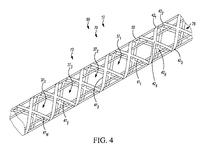
latticed,
i.e., comprises a lattice 70. Thus, in this example, the lattice 70
constitutes at least
part of the shaft 12 and/or at least part of the blade 14. Specifically, in
this example,
the shaft 12 includes a portion 71 of the lattice 70, while the blade 14
includes
another portion 73 of the lattice 70. In this embodiment, the lattice 70
occupies at
least a majority (i.e., a majority or an entirety) of the length of the shaft
12 and at
least a majority (i.e., a majority or an entirety) of the length of the blade
14.
In some embodiments, the lattice 70 comprises a framework of structural
members
411-41E that intersect one another. In some embodiments, the structural
members
411-41E may be arranged in a regular arrangement repeating over the lattice
70. In
some cases, the lattice 70 may be viewed as made up of unit cells 371-37c each
including a subset of the structural members 411-41E that forms the regular
9

CA 03141358 2021-11-19
WO 2020/232552 PCT/CA2020/050686
arrangement repeating over the lattice 70. Each of these unit cells 371-37c
can be
viewed as having a voxel, which refers to a notional three-dimensional space
that it
occupies. In other embodiments, the structural members 411-41E may be arranged
in
different arrangements over the lattice 70 (e.g., which do not necessarily
repeat over
the lattice 70, do not necessarily define unit cells, etc.).
The lattice 70, including its structural members 411-41E, may be configured in
any
suitable way.
In this embodiment, the structural members 411-41E are elongate members that
intersect one another at nodes 421-42N. The elongate members 411-41E may
sometimes be referred to as "beams" or "struts". Each of the elongate members
411-
41E may be straight, curved, or partly straight and partly curved. While in
some
embodiments at least some of the nodes 421-42N (i.e. some of the nodes 421-42N
or
every one of the nodes 421-42N) may be formed by having the structural members
411-41E forming the nodes affixed to one another (e.g., chemically fastened,
via an
adhesive, etc.), as shown in Figures 12 and 13, in some embodiments at least
some
of the nodes 421-42N (i.e. some of the nodes 421-42N or every one of the nodes
421-
42N) may be formed by having the structural members 411-41E being unitary
(e.g.,
integrally made with one another, fused to one another, etc.), as shown in
Figures
14 and 15. Also, in this embodiment, the nodes 421-42N may be thicker than
respective ones of the elongate members 411-41 E that intersect one another
thereat,
as shown in Figure 13 and 15, while in other embodiments the nodes 421-42N may
have a same thickness as respective ones of the elongate members 411-41E that
intersect one another thereat.
In this embodiment, the structural members 411-41E may have any suitable
shape,
as shown in Figures 16 to 21. That is, a cross-section of a structural member
411
across a longitudinal axis of the structural member 411 may have any suitable
shape,
for instance: a circular shape, an oblong shape, an elliptical shape, a square
shape,
a rectangular shape, a polygonal shape (e.g. triangle, hexagon, and so on),
etc.

CA 03141358 2021-11-19
WO 2020/232552 PCT/CA2020/050686
Moreover, in this embodiment, the structural member 411 may comprise any
suitable
structure and any suitable composition, as shown in Figures 22 to 27. As an
example, the structural member 411 may be solid (i.e. without any void) and
composed of a material 50, as shown in Figure 22. In another embodiment, the
structural member 411 may comprise the material 50 and another material 511
inner
to the material 50, as shown in Figure 23. In another embodiment, the
structural
member 411 may comprise the material 50, the other material 511 inner to the
material 50 and another material 512 outer to the material 50, as shown in
Figure 24.
In another embodiment, the structural member 411 may be composed of the
material
50 and may comprise a void 44 that is not filled by any specific solid
material, as
shown in Figure 25. In another embodiment, the structural member 411 may
comprise the material 50, another material outer to the material 50 and the
void 44
that is not filled by any specific solid material, as shown in Figure 26. In
another
embodiment, the structural member 411 may comprise the material 50 and a
plurality
of reinforcements 53 (e.g. continuous or chopped fibers), as shown in Figure
27.
More particularly, in this embodiment, the lattice 70 includes a truss 73, as
shown in
Figure 28. In this example, the truss 73 constitutes the portion 71 of the
lattice 70 of
the shaft 12. The truss 73 comprises peripheral portions 741-744 that are part
of
walls 751-754 of the shaft 12 that define the periphery 30 of the shaft 12,
including its
front surface 16, rear surface 18, top surface 22 and bottom surface 24. Each
of the
peripheral portions 741-744 of the truss 73 includes respective ones of the
elongate
members 411-41E and the nodes 421-42N of the lattice 70. A front one of the
peripheral portions 741-744 of the truss 73 is part of a front one of the
walls 751-754
of the shaft 12 that includes its front surface 16, a rear one of the
peripheral portions
741-744 of the truss 73 is part of a rear one of the walls 751-754 of the
shaft 12 that
includes its rear surface 18, a top one of the peripheral portions 741-744 of
the truss
73 is part of a top one of the walls 751-754 of the shaft 12 that includes its
top
surface 22, and a bottom one of the peripheral portions 741-744 of the truss
73 is

CA 03141358 2021-11-19
WO 2020/232552 PCT/CA2020/050686
part of a bottom one of the walls 751-754 of the shaft 12 that includes its
bottom
surface 24.
In this example, between its peripheral portions 741-744, the truss 73
includes a void
76, as shown in Figure 34. In this embodiment, the shaft 12 comprises a core
77
disposed in the void 76 of the truss 73, as shown in Figures 35 and 36. The
core 77
may be entirely disposed inside the lattice 70 such that it does not engage a
surface
of the covering 69, as shown in Figure 35, although alternatively the core 77
may
engage the lattice 70 and the inner surface of the covering 69, in the
embodiment
shown in Figure 36. For instance, the core 77 may include one or more internal
members of foam, elastomeric material, etc. Alternatively, in other
embodiments, the
void 76 of the truss 73 may be hollow (i.e., not contain any core), or may be
filled by
the core 77 having a shape defining an inner void 112.
Also, in this embodiment, the lattice 70 includes another truss 78, as shown
in
Figures 38 and 39. In this example, the truss 78 constitutes the portion 73 of
the
lattice 70 of the blade 14. The truss 78 comprises peripheral portions 791-796
that
are part of walls 801-806 of the blade 14 that define the periphery 50 of the
blade 14,
including its front surface 52, rear surface 54, top edge 56, toe edge 58,
heel edge
59, and bottom edge 60. Each of the peripheral portions 791-796 of the truss
78
includes respective ones of the elongate members 411-41 E and the nodes 421-
42N of
the lattice 70. A front one of the peripheral portions 791-796 of the truss 78
is part of
a front one of the walls 801-806 of the blade 14 that includes its front
surface 52, a
rear one of the peripheral portions 791-796 of the truss 78 is part of a rear
one of the
walls 801-806 of the blade 14 that includes its rear surface 54, a top one of
the
peripheral portions 791-796 of the truss 78 is part of a top one of the walls
801-806 of
the blade 14 that includes its top edge 56, a toe one of the peripheral
portions 791-
796 of the truss 78 is part of a toe one of the walls 801-806 of the blade 14
that
includes its toe edge 48, a heel one of the peripheral portions 791-796 of the
truss 78
is part of a heel one of the walls 801-806 of the blade 14 that includes its
heel edge
12

CA 03141358 2021-11-19
WO 2020/232552 PCT/CA2020/050686
59, and a bottom one of the peripheral portions 791-796 of the truss 78 is
part of a
bottom one of the walls 801-806 of the blade 14 that includes its bottom edge
60.
In this example, between its peripheral portions 791-796, the truss 78
includes a void
81. In this embodiment, the blade 14 comprises a core 82 disposed in the void
81 of
the truss 78. For instance, the core 82 may include one or more internal
members of
foam, elastomeric material, etc. Alternatively, in other embodiments, the void
81 of
the truss 78 may be hollow (i.e., not contain any core).
Material 50 of the lattice 70 can be of any suitable kind. In this embodiment,
the
material 50 is composite material. More particularly, in this embodiment, the
composite
material 50 is fiber-reinforced composite material comprising fibers disposed
in a
matrix. For instance, in some embodiments, the material 50 may be fiber-
reinforced
plastic (FRP ¨ a.k.a., fiber-reinforced polymer), comprising a polymeric
matrix may
include any suitable polymeric resin, such as a thermoplastic or thermosetting
resin,
like epoxy, polyethylene, polypropylene, acrylic, thermoplastic polyurethane
(TPU),
polyether ether ketone (PEEK) or other polyaryletherketone (PAEK),
polyethylene
terephthalate (PET), polyvinyl chloride (PVC), poly(methyl methacrylate)
(PMMA),
polycarbonate, acrylonitrile butadiene styrene (ABS), nylon, polyimide,
polysulfone,
polyamide-imide, self-reinforcing polyphenylene, polyester, vinyl ester, vinyl
ether,
polyurethane, cyanate ester, phenolic resin, etc., a hybrid thermosetting-
thermoplastic
resin, or any other suitable resin, and fibers such as carbon fibers, glass
fibers,
polymeric fibers such as aramid fibers (e.g., Kevlar fibers), boron fibers,
silicon carbide
fibers, metallic fibers, ceramic fibers, etc. In some embodiments, the fibers
of the fiber-
reinforced composite material 50 may be provided as layers of continuous
fibers, such
as pre-preg (i.e., pre-impregnated) tapes of fibers (e.g., including an amount
of resin)
or as continuous fibers deposited (e.g., printed) along with rapidly-curing
resin forming
the polymeric matrix. In other embodiments, the fibers of the fiber-
reinforced
composite material 50 may be provided as fragmented (e.g., chopped) fibers
dispersed
in the polymeric matrix.
13

CA 03141358 2021-11-19
WO 2020/232552 PCT/CA2020/050686
In some embodiments, the material 50 of the lattice 70 may be identical
throughout the
lattice 70. In other embodiments, the material 50 of the lattice 70 may be
different in
different parts of the lattice 70. For example, in some embodiments, the
material 50 of
the portion 71 of the lattice 70 that is part of the shaft 12 may be different
from the
material 50 of the portion 73 of the lattice 70 that is part of the blade 14.
Alternatively or
additionally, in some embodiments, the material 50 of one region of the
portion 71 of
the lattice 70 that is part of the shaft 12 may be different from the material
50 of another
region of the portion 71 of the lattice 70 that is part of the shaft 12,
and/or the material
50 of one region of the portion 73 of the lattice 70 that is part of the blade
14 may be
.. different from the material 50 of another region of the portion 73 of the
lattice 70 that is
part of the blade 14.
The material 50 of the lattice 70 may be polymeric material (e.g., not fiber-
reinforced),
metallic material, or ceramic material in other embodiments.
The lattice 70 of the hockey stick 10 may be designed to have properties of
interest
in various embodiments.
For example, in some embodiments, strength of the lattice 70 may be at least
800N,
in some cases at least 1000N, some cases at least 1100N, some cases at least
1200N, and in some cases at least 1300N, and/or in some cases no more than
2000N, in some cases no more than 1500N, in some cases no more than 1400N, in
some cases no more than 1300N, in some cases no more than 1200N, in some
cases no more than 1100N, in some cases no more than 1000N, in some cases
.. even less.
The strength of the lattice 70 may be measured by a 3-points-bending test to
failure,
as shown in Fig 61. In this example, the supports used for the 3-points-
bending test
to failure may be spaced from one another by a distance of approximately 1050
mm,
while the strength corresponds to the force applied at the midpoint between
the
supports.
14

CA 03141358 2021-11-19
WO 2020/232552 PCT/CA2020/050686
In some embodiments, the lattice 70 may include distinct zones 921-92z that
are
structurally different from one another. For instance, this may be useful to
modulate
properties, such as the strength, flex, stiffness, etc., of the zones 921-92z
of the
lattice 70.
For example, the zones 921-92z of the lattice 70 may include a zone 921 at the
proximal end portion 26 of the shaft 12, a zone 922 at the distal end portion
28 of the
shaft 12, a zone 923 at the toe region 61 of the blade 14, a zone 924 at the
heel
region 62 of the blade 14, and a zone 925 at the intermediate region 63 of the
blade
14.
In this embodiment, delimitations of the zones 921-92z of the lattice 70 are
configured to match different parts of the hockey stick 10 which may be
subject to
.. different stresses and may require different mechanical properties.
Accordingly, the
zones 921-92z of the lattice 70 may have different mechanical properties to
facilitate
puck handling, to increase power transmission and/or energy transmission from
the
hockey stick 10 to the puck during wrist shots and/or slap shots, to lighten
the
hockey stick, to increase impact resistance of the hockey stick 10, to
increase
elongation at break of the hockey stick 10, to position a kickpoint, to reduce
manufacturing costs, and so on.
Mechanical properties of the zones 921-92z of the lattice 70 may be achieved
by any
suitable means.
For example, in some embodiments, a shape of the unit cells 371-37c of each
zone
921 may be pre-determined to increase or diminished the aforementioned
mechanical properties.

CA 03141358 2021-11-19
WO 2020/232552 PCT/CA2020/050686
As another example, in some embodiments, the voxel (or size) of the unit cells
371-
37c of each zone 921 may be pre-determined to increase or diminished the
aforementioned mechanical properties.
As another example, in some embodiments, a thickness of elongate members 411-
41E of each zone 921 may be pre-determined to increase or diminished the
aforementioned mechanical properties..
As another example, in some embodiments, the material 50 of each zone 921 may
be pre-determined to increase or diminished the aforementioned mechanical
properties.
As such, in some embodiments, the shape of the unit cells 371-37c (and thus
the
shape of the elongate members 411-41E and/or nodes 421-42N), the voxel (or
size) of
the unit cells 371-37c, a thickness of elongate members 411-41E of each zone
921
and/or the material 50 of each zone 921 may vary between the zones 921-92z.
For
instance, in some embodiments, adjacent ones of the nodes 421-42N in one
region
921 of the lattice 70 may be located closer to one another than adjacent ones
of the
nodes 421-42N in another region of the lattice 70, as shown in Figure 40 and
41,
and/or the thickness of the elongate members 411-41E and nodes 421-42N in one
region 921 of the lattice 70 may be greater than the thickness of the elongate
members 411-41E and nodes 421-42N in another region 92j of the lattice 70, as
shown in Figures 42 and 43.
.. In this embodiment, the distinct zones 921-92z of the lattice 70 differ in
stiffness
and/or stiffness. For example, in some embodiments, a ratio of the stiffness
of a
given one of the zones 921-92z of the lattice 70 over the stiffness of another
one of
the zones 921-92z of the lattice 70 may be at least 10%, in some embodiments
at
least 20%, in some embodiments at least 30%, in some embodiments at least 40%,
.. in some embodiments even more. Similarly, in some embodiments, a ratio of
the
strength of a given one of the zones 921-92z of the lattice 70 over the
strength of
16

CA 03141358 2021-11-19
WO 2020/232552 PCT/CA2020/050686
another one of the zones 921-92z of the lattice 70 may be at least 10%, in
some
embodiments at least 20%, in some embodiments at least 30%, in some
embodiments at least 40%, in some embodiments even more.
In this embodiment, the distinct zones 921-92z of the lattice 70 differ in
resilience.
For example, in some embodiments, a ratio of the resilience of a given one of
the
zones 921-92z of the lattice 70 over the resilience of another one of the
zones 921-
92z of the lattice 70 may be at least 5%, in some embodiments at least 10%, in
some embodiments at least 20%, in some embodiments at least 30%, in some
embodiments even more.
In this embodiment, the covering 69 may covers at least part of the open
structure
68 of the hockey stick 10. In that sense, the covering 69 may be viewed as a
"skin".
In this embodiment, the covering 69 covers at least a majority (i.e., a
majority or an
entirety) of the lattice 70. More particularly, in this embodiment, the
covering 69
covers the entirety of the lattice 70, as notably shown in Figure 6. The
hockey stick
10 may thus externally appear like a conventional hockey stick, as its open
structure
68 is concealed.
In other embodiments, the covering 69 may not cover the entirety of the
lattice open
structure 68 and may therefore comprise apertures, as shown in Figure 5.
In this embodiment, the shaft 12 includes a portion 86 of the covering 69,
while the
blade 14 includes another portion 87 of the covering 69. The portion 86 of the
covering 69 thus covers the truss 73 of the shaft 12, whereas the portion 87
of the
covering 69 covers the truss 78 of the blade 14.
Material 90 of the covering 69 can be of any suitable kind. In this
embodiment, the
material 90 is composite material. More particularly, in this embodiment, the
composite
material 90 is fiber-reinforced composite material comprising fibers disposed
in a
matrix. For instance, in some embodiments, the material 90 may be fiber-
reinforced
17

CA 03141358 2021-11-19
WO 2020/232552 PCT/CA2020/050686
plastic (FRP ¨ a.k.a., fiber-reinforced polymer), comprising a polymeric
matrix may
include any suitable polymeric resin, such as a thermoplastic or thermosetting
resin,
like epoxy, polyethylene, polypropylene, acrylic, thermoplastic polyurethane
(TPU),
polyether ether ketone (PEEK) or other polyaryletherketone (PAEK),
polyethylene
terephthalate (PET), polyvinyl chloride (PVC), poly(methyl methacrylate)
(PMMA),
polycarbonate, acrylonitrile butadiene styrene (ABS), nylon, polyimide,
polysulfone,
polyamide-imide, self-reinforcing polyphenylene, polyester, vinyl ester, vinyl
ether,
polyurethane, cyanate ester, phenolic resin, etc., a hybrid thermosetting-
thermoplastic
resin, or any other suitable resin, and fibers such as carbon fibers, glass
fibers,
polymeric fibers such as aramid fibers (e.g., Kevlar fibers), boron fibers,
silicon carbide
fibers, metallic fibers, ceramic fibers, etc. In some embodiments, the fibers
of the fiber-
reinforced composite material 50 may be provided as layers of continuous
fibers, such
as pre-preg (i.e., pre-impregnated) tapes of fibers (e.g., including an amount
of resin)
or as continuous fibers deposited (e.g., printed) along with rapidly-curing
resin forming
the polymeric matrix. In other embodiments, the fibers of the fiber-
reinforced
composite material 90 may be provided as fragmented (e.g., chopped) fibers
dispersed
in the polymeric matrix.
In some embodiments, the material 90 of the covering 69 may be identical
throughout
the covering 69. In other embodiments, the material 90 of the covering 69 may
be
different in different parts of the covering 69. For example, in some
embodiments, the
material 90 of the portion 86 of the covering 69 that is part of the shaft 12
may be
different from the material 90 of the portion 87 of the covering 69 that is
part of the
blade 14. Alternatively or additionally, in some embodiments, the material 90
of one
region of the portion 86 of the covering 69 that is part of the shaft 12 may
be different
from the material 90 of another region of the portion 86 of the covering 69
that is part of
the shaft 12, and/or the material 90 of one region of the portion 87 of the
covering 69
that is part of the blade 14 may be different from the material 90 of another
region of
the portion 87 of the covering 69 that is part of the blade 14.
In other embodiments, the material 90 of the covering 69 may be (non-fiber-
reinforced)
18

CA 03141358 2021-11-19
WO 2020/232552 PCT/CA2020/050686
polymeric material, metallic material, or ceramic material.
The hockey stick 10, including the lattice 70 and the covering 69, may be
manufactured in any suitable way.
For example, in some embodiments, the lattice 70 may be an additively-
manufactured
lattice that is additively manufactured, i.e., made by additive manufacturing,
also known
as 3D printing, in which the material 50 thereof initially provided as
feedstock (e.g., as
powder, liquid, filaments, fibers, and/or other suitable feedstock), which can
be referred
to as 3D-printed material, is added by a machine (i.e., a 3D printer) that is
computer-
controlled (e.g., using a digital 3D model such as a computer-aided design
(CAD) file)
to create it in its three-dimensional form (e.g., layer by layer, from a pool
of liquid,
applying continuous fibers, or in any other way, normally moldlessly, i.e.,
without any
mold). This is in contrast to subtractive manufacturing (e.g., machining)
where material
is removed and molding where material is introduced into a mold's cavity.
Any 3D-printing technology may be used to make the lattice 70. For instance,
in
some embodiments, fused deposition modeling (FDM), digital light processing
(DLP), stereolithography (SLA), selective laser sintering (SLS), material
jetting (MJ),
binder jetting (BJ), continuous-fiber 3D printing, and/or any other suitable
3D-printing
technology may be used. Examples of suitable 3D-printing technologies may
include
those available from Carbon (www.carbon3d.com), EOS (https://www.eos.info/en),
HP, (https://www8. hp. com/ca/en/printers/3d-printers. html),
Arevo
(https://arevo.com), and Continuous
Composites
(https://www.continuouscomposites.com/).
In this embodiment, as it includes the fiber-reinforced composite material 50,
the
lattice 70 may be 3D-printed using continuous-fiber 3D printing technology.
For
instance, in some embodiments, this may allow each of one or more of the
fibers of
the fiber-reinforced composite material 50 to extend along at least a
significant part,
such as at least a majority (i.e., a majority or an entirety), of a length of
the lattice 70
19

CA 03141358 2021-11-19
WO 2020/232552 PCT/CA2020/050686
(e.g., monofilament winding). This may enhance the strength, the impact
resistance,
and/or other properties of the hockey stick 10.
The lattice 70 can be designed and 3D-printed to impart its properties and
functions,
such as those discussed above, while helping to minimize its weight. The 3D-
printed
material 50 constitutes the lattice 70. Specifically, the elongate members 411-
41E
and the nodes 421-42N of the lattice 70 include respective parts of the 3D-
printed
material 50 that are created by the 3D-printer. Fibers may be printed by the
3D
printer along with rapidly-curing resin to form the fiber-reinforced composite
material
.. 50.
The lattice 70 may be manufactured in any other suitable way in other
embodiments,
including by technology other than 3D printing.
For instance, in some embodiments, the lattice 70 may be provided by
positioning
pre-preg tapes of fibers (e.g., including an amount of resin) to form the
elongate
members 411-41E and the nodes 421-42N of the lattice 70 and heating it (e.g.,
in a
mold) to form its fiber-reinforced composite material 50 once cured.
For instance, pre-preg tapes of fibers may be enrolled around a support 108
(e.g. a
mandrel, foam, procured part, and so on) with a pre-determined pitch and a pre-
determined angle to form a "green" lattice. The pre-determined pitch and pre-
determined angle used to form the green lattice may contribute to determine
the
geometry of the unit cells 371-37c and thus mechanical properties (e.g.
stiffness) of
the lattice 70.
For example, in some embodiments, as shown in Figures 44A to 44H, the lattice
70
may comprise segments 1061-1068 each formed using one continuous string of pre-
preg tape and the structural members 411-41E may have a thickness of 1 mm. In
order to form the lattice 70, the pre-preg tape may have a thickness of 1 mm
and be
enrolled successively around the support 108, at a pre-determined angle. For

CA 03141358 2021-11-19
WO 2020/232552 PCT/CA2020/050686
example, segments 1065-1068 forming edges (i.e. corners) of the lattice 70 may
be
enrolled at an angle of 0 relative to a longitudinal axis of the support,
while
segments 1061, 1063 may be enrolled at an angle of about 45 relative to a
longitudinal axis of the support and segments 1062, 1064 may be enrolled at an
angle of about -45 relative to a longitudinal axis of the support. Each time
segments 1061-1068 cross one another, a node 421 may be created ¨ each node
421
having a thickness that is superior to the thickness of the segments 1061-1068
in this
embodiment.
As another example, in some embodiments, to obtain a similar lattice 70 using
pre-
preg tape having a thickness of 0.25 mm, four successive passes of the
aforementioned steps may be repeated, which in comparison with the preceding
embodiment may provide a lattice 70 having superior strength and interlaminar
shear.
It is noted that, in other embodiments, width, thickness and material of the
pre-preg
tape used for manufacturing the lattice 70 may vary for each segment
106iand/or for
each pass, and that any stage layers of material (e.g. the covering 69) may be
added under or over the.
The obtained "green" 70 may be subsequently cured or molded, for example using
an autoclave, vacuum molding, RTM, compression molding (e.g. with a bladder or
a
mandrel to control an external dimension of the lattice during and after
molding), or
so on.
The covering 69 may be provided about the lattice 70 in any suitable way in
various
embodiments.
For example, in some embodiments, the covering 69 may be an additively-
manufactured covering that is additively manufactured, i.e., 3D-printed. Any
3D-
printing technology may be used to make the covering 69, such as those
discussed
21

CA 03141358 2021-11-19
WO 2020/232552 PCT/CA2020/050686
above. For instance, in some embodiments, the covering 69 may be 3D-printed
using continuous-fiber 3D printing technology. This may allow each of one or
more
of the fibers of the fiber-reinforced composite material 90 to extend along at
least a
significant part, such as at least a majority (i.e., a majority or an
entirety), of a length
of the covering 69 (e.g., monofilament winding).
As another example, in some embodiments, the covering 69 may be provided by
wrapping pre-preg tapes of fibers (e.g., including an amount of resin) about
the
lattice 70 and heating it (e.g., in a mold) to form its fiber-reinforced
composite
material 90 once cured.
The hockey stick 10, including the shaft 12 and the blade 14, may be
implemented in
various other ways in other embodiments.
.. For example, in some embodiments, the lattice 70 may have any suitable
cross-
section shape such as a pentagonal shape, a hexagonal shape, a round shape, an
elliptical shape, and so on, as shown in Figures 29 to 34. Additionally, the
shape of
the cross-section of the lattice 70 may vary from a zone 92 to another 92.
In this embodiment, the portion 73 of the lattice 70 that is part of the blade
14 may
be structurally different from the portion 71 of the lattice 70 that is part
of the shaft
12. For example, an average voxel of the unit cells 371-37c of the portion 73
of the
lattice 70 may be significantly smaller than an average voxel of the unit
cells 371-37c
of the portion 71 of the lattice 70 and in some embodiments a ratio of the
average
.. voxel of the portion 73 over the average voxel of the portion 71 may be
less than
0.95, in some embodiments less than 0.75, in some embodiments less than 0.50,
in
some embodiments less than 0.25, in some embodiments even less. As another
example, the shape of the unit cells 371-37c of the portion 73 of the lattice
70 may be
different from the shape of the unit cells 371-37c of the portion 71 of the
lattice 70
such that the portion 73 is significantly stiffer than the portion 71. As
another
example, in some embodiments, the portion 73 of the lattice 70 that is part of
the
22

CA 03141358 2021-11-19
WO 2020/232552 PCT/CA2020/050686
blade 14 comprises a framework defining a non-hollow lattice, while the
portion 71 of
the lattice 70 that is part of the shaft 12 comprises a framework defining a
hollow
lattice.
.. As another example, in some embodiments, the structural members 411-41E of
the
lattice 70 may be implemented in various other ways. For example, in some
embodiments, as shown in Figure 45, the structural members 411-41E may be
planar
members that intersect one another at vertices 1421-142v. The planar members
411-
41 E may sometimes be referred to as "faces". Each of the planar members 411-
41E
may be straight, curved, or partly straight and partly curved.
The lattice 70 may be implemented in any other suitable way and have any other
suitable configuration. Examples of other possible configurations for the
lattice 70 in
other embodiments are shown in Figures 7 to 11.
In some embodiments, the hockey stick may be an "intelligent" hockey stick.
That is,
the hockey stick 10 may comprise sensors 2801-280s to sense a force acting on
the
hockey stick, a position, a speed, an acceleration and/or a deformation of the
hockey
stick 10 during play or during a testing (e.g. of hockey sticks, of players,
etc.). More
particularly, in this embodiment, the lattice 70 comprises the sensors 2801-
280s.
More specifically, in this embodiment, the sensors 2801-280s are associated
with an
additively-manufactured component of the lattice 70.
Further, in this embodiment, the hockey stick 10 may comprise actuators 2861-
286A.
Specifically, the actuators 2861-286A may be associated with at least some of
sensors 2801-280s and may be configured to respond to a signal of the sensors
2801-280s. In particular, the sensors 2801-280s may be responsive to an event
(e.g.
an increase in acceleration of the hockey stick 10, an increase of a force
acting on
the hockey stick 10, an increase of the deformation of the hockey stick 10,
etc.) to
cause the actuators 2861-286A to alter the additively-manufactured component
to
alter the lattice 70 (e.g. to increase resilience, to increase stiffness,
etc.).
23

CA 03141358 2021-11-19
WO 2020/232552 PCT/CA2020/050686
Practically, in this embodiment, this may be achieved using piezoelectric
material
290 implementing the sensors 2801-280s, the piezoelectric material 290 being
comprised in the additively-manufactured component of the lattice 70.
In other embodiments, more or less of the hockey stick 10 may be latticed as
discussed above.
For example, in some embodiments, as shown in Figure 46, the lattice 70 may
constitute at least part (e.g., occupy at least a majority, i.e., a majority
or an entirety,
of the length) of the shaft 12, but not constitute any part of the blade 14.
That is, the
shaft 12 may include all of the lattice 70, while the blade 14 may not include
any
lattice.
As another example, in some embodiments, as shown in Figure 47, the lattice 70
may constitute at least part (e.g., occupy at least a majority, i.e., a
majority or an
entirety, of the length) of the blade 14, but not constitute any part of the
shaft 12.
That is, the blade 14 may include all of the lattice 70, while the shaft 12
may not
include any lattice.
As yet another example, as shown in Figures 48, the shaft 12 and/or the blade
14
may include two or more lattices like the lattice 70 that are separate (e.g.,
spaced
apart) from one another.
For instance, in some embodiments, as shown in Figures 48 and 49, the blade 14
may comprises lattices 1701-170L similar to the lattice 70 that are separate
from one
another. In this example, adjacent ones of the lattices 1701-170L are spaced
from
one another by a rib 92 extending from a front one of the walls 801-806 of the
blade
14 to a back one of the walls 801-806 of the blade 14. The lattices 1701-170L
may be
or include distinct zones structurally different from one another, as
discussed above.
For example, in some embodiments, a lower one of the lattices 1701-170L may be
24

CA 03141358 2021-11-19
WO 2020/232552 PCT/CA2020/050686
less stiff or more resilient than a higher one of the lattices 1701-170L
(e.g., to better
absorb impacts).
In some embodiments, as shown in Figure 50, the lattices 1701-170L may not be
spaced from one another by a rib 92 and may engage one another. For example,
in
some embodiments, the blade 14 may comprise different lattices 1701-170L each
covering a given one of the toe portion 61, the heel portion 62 and the
intermediate
portion 63, as shown in Figure 51. As another example, in some embodiments,
the
blade 14 may comprise different lattices 1701, 1702 the lattice 1701 defining
an upper
portion of the blade 14 and the lattice 1702 defining a lower portion of the
blade 14,
the lattice 1702 being lighter but less stiff than the lattice 1701 in order
to facilitate
handling (e.g. by increasing vibration damping and diminishing weight of the
blade
14) and still increase energy transfer to a hockey puck (e.g. by having a
relatively
stiff blade 14), as shown in Figure 52.
In some embodimentsõ as shown in Figure 53, the shaft 12 may comprises
lattices
2701-270L similar to the lattice 70 that are separate from one another. In
this
example, adjacent ones of the lattices 2701-270L are spaced from one another
by a
non-latticed portion 94. The lattices 2701-270L may be or include distinct
zones
structurally different from one another, as discussed above. For example, in
some
embodiments, a lower one of the lattice 2701-270L may be less stiff or more
resilient
than a higher one of the lattices 2701-270L (e.g., to adjust the flex of the
hockey stick
10).
In some embodiments, as shown in Figures 54 to 56, the lattice 70 may comprise
recesses 1201-12OR and/or ribs 1221-122R in order to provide a stick 10 which
facilitates puck handling, facilitates grip, increases power transmission
and/or energy
transmission from the hockey stick 10 to the puck during wrist shots and/or
slap
shots, is light, increases impact resistance of the hockey stick 10, increases
elongation at break of the hockey stick 10, is relatively cheap to
manufacture, and so
on. In some embodiments, a depth of the recesses 1201-12OR and/or ribs 1221-
122R

CA 03141358 2021-11-19
WO 2020/232552 PCT/CA2020/050686
may be insignificant and may improve an appearance and a touch (i.e. a feel)
of the
stick 10. For example, in some embodiments, the depth of the recesses 1201-
12OR
and/or ribs 1221-122R may be no more than 1.5 mm, in some embodiments no more
than 1 mm, in some embodiments no more than 0.5 mm and in some embodiments
even less. However, in some embodiments, the depth of the recesses 1201-12OR
and/or ribs 1221-122R may be significant and may increase stiffness of the
stick 10
and/or reduce weight of the stick 10. For example, in some embodiments, the
depth
of the recesses 1201-12OR and/or ribs 1221-122R may be at least 1.5 mm, in
some
embodiments at least 2 mm, in some embodiments at least 3 mm, in some
embodiments at least 4 mm, in some embodiments at least 5 mm, and in some
embodiments even more.
Further, in some embodiments, as shown in Figure 56, the lattice 70 may be
anisotropic. For instance, a torsional stiffness of the lattice 70 may be
greater in one
direction than in another opposite direction. This may allow the stick to be
light, yet
to resist repetitive impacts when the impacts are expected to be mostly in the
same
direction. In this embodiment, this is achieved by having the lattice 70
defining rib
1221, 1222 which are configured for supporting the lattice 70 when the lattice
70 is
subject to torsional stress in one direction but not for supporting the
lattice 70 when
the lattice 70 is subject to torsional stress in the other opposite direction.
Alternatively, in some embodiments, instead of being formed by the lattice 70,
the
1201-12OR and/or ribs 1221-122R may be formed by the covering 69 around the
lattice 70.
In some embodiments, the hockey stick 10 may comprise one or more additively-
manufactured components, instead of or in addition to the lattice 70. That is,
the
lattice 70 is one example of an additively-manufactured component in
embodiments
where it is 3D-printed. Such one or more additively-manufactured components of
the
hockey stick 10 may be 3D-printed as discussed above, using any suitable 3D-
printing technology, similar to what was discussed above in relation to the
lattice 70
26

CA 03141358 2021-11-19
WO 2020/232552 PCT/CA2020/050686
in embodiments where the lattice 70 is 3D-printed. The hockey stick 10 may
comprise the lattice 70, which may or may not be additively-manufactured, or
may
not have any lattice in embodiments where the hockey stick 10 comprises such
one
or more additively-manufactured components.
For example, in some embodiments, as shown in Figure 57, the blade 14 may
comprises an additively-manufactured core 182. In this embodiment, the
additively-
manufactured core 182 comprises a 3D-printed lattice 282 that can be
constructed
and configured similarly to what is discussed above in relation of the lattice
70, in
embodiments where the lattice 70 is 3D-printed.
The 3D-printed lattice 282 of the core 182 of the blade 14 may be manufactured
in
any suitable way, using any suitable materials and may have any suitable
mechanical properties, such as those described with regards to the lattice 70.
In this
embodiment, the 3D-printed lattice 282 is manufactured prior to the lattice
70, while
in other embodiments, the 3D-printed lattice 282 and the lattice 70 are
manufactured
simultaneously.
In some embodiments, the method of manufacture, the materials and the
structure
of the lattices 70, 282 forming the blade 14 may differ. For instance, the
lattice 282
may be lighter (i.e. less dense) but less stiff than the lattice 70 which is
over the
lattice 282 and thus may provide stiffness to the blade 14 more efficiently.
While in this embodiment the hockey stick 10 is a player stick for the user
that is a
forward, i.e., right wing, left wing, or center, or a defenseman, in other
embodiments,
as shown in Figure 58, the hockey stick 10 may be a goalie stick where the
user is a
goalie. The goalie stick 10 may be constructed according to principles
discussed
herein. For example, in some embodiments, the goalie stick 10 may comprise the
lattice 70 (e.g., which may be additively-manufactured or otherwise made)
and/or
one or more other additively-manufactured components, as discussed above.
27

CA 03141358 2021-11-19
WO 2020/232552 PCT/CA2020/050686
The goalie stick 10 comprises a paddle 497 that may be constructed according
to
principles discussed herein. For instance, in some embodiments, the paddle 497
may be disposed between the shaft 12 and the blade 14. The paddle 497 is
configured to block hockey pucks from flying into the net. A periphery 430 of
the
paddle 497 includes a front surface 416 and a rear surface 418 opposite one
another, as well as a top edge 422 and a bottom edge 424 opposite one another.
Proximal and distal end portions 426, 428 of the paddle 497 are spaced apart
in a
longitudinal direction of the paddle 497, respectively adjacent to the shaft
12 and the
blade 14, and define a length of the paddle 497.
More particularly, in this
embodiment, at least part of the goalie stick 10 is latticed, i.e., comprises
the lattice
70. Thus, in this example, the lattice 70 (e.g., which may be additively-
manufactured
or otherwise made) and/or one or more other additively-manufactured components
constitutes at least part of the shaft 12 and/or at least part of the blade 14
and/or at
least part of the paddle 497 in a similar fashion as described above with
regards to
the hockey player stick 10.
Although in this embodiment the sporting implement 10 is a hockey stick, in
other
embodiments, the sporting implement 10 may be any other implement used for
striking, propelling or otherwise moving an object in a sport.
For example, in other embodiments, as shown in Figure 59, the sporting
implement
10 may be a lacrosse stick for a lacrosse player, in which the object-
contacting
member 14 of the lacrosse stick 10 comprises a lacrosse head for carrying,
shooting
and passing a lacrosse ball.
The lacrosse head 14 comprises a frame 623 and a pocket 631 connected to the
frame 623 and configured to hold the lacrosse ball. The frame 623 includes a
base
641 connected to the shaft 12 and a sidewall 643 extending from the base 641.
In
this embodiment, the sidewall 643 is shaped to form a narrower area 650
including a
ball stop 651 adjacent to the base 641 and an enlarged area 655 including a
scoop
28

CA 03141358 2021-11-19
WO 2020/232552 PCT/CA2020/050686
656 opposite to the base 641. Also, in this embodiment, the pocket 31 includes
a
mesh 660.
The lacrosse stick 10 may be constructed according to principles discussed
herein.
For example, in some embodiments, the lacrosse stick 10 may comprise the
lattice
70 (e.g., which may be additively-manufactured or otherwise made) and/or one
or
more other additively-manufactured components, as discussed above. For
instance,
in some embodiments, the lattice 70 (e.g., which may be additively-
manufactured or
otherwise made) and/or one or more other additively-manufactured components
may constitute at least part of the shaft 12 and/or at least part of the
lacrosse head
14, such as at least part of the frame 623 and/or at least part of the pocket
631,
according to principles discussed herein.
In other embodiments, as shown in Figure 60, the sporting implement 10 may be
a
.. ball bat (e.g., a baseball or softball bat) for a ball player, in which the
object-
contacting member 14 of the ball bat 10 comprises a barrel for hitting a ball.
The ball bat 10 may be constructed according to principles discussed herein.
For
example, in some embodiments, the ball bat 10 may comprise the lattice 70
(e.g.,
which may be additively-manufactured or otherwise made) and/or one or more
other
additively-manufactured components, as discussed above. For instance, in some
embodiments, the lattice 70 (e.g., which may be additively-manufactured or
otherwise made) and/or one or more other additively-manufactured components
may constitute at least part of a handle 866 of the elongate holdable member
12
and/or at least part of the barrel 14, according to principles discussed
herein.
Any feature of any embodiment described herein may be combined with any
feature
of any other embodiment described herein in some examples of implementation.
Certain additional elements that may be needed for operation of certain
embodiments have not been described or illustrated as they are assumed to be
29

CA 03141358 2021-11-19
WO 2020/232552 PCT/CA2020/050686
within a purview of those of ordinary skill. Moreover, certain embodiments may
be
free of, may lack and/or may function without any element that is not
specifically
disclosed herein.
Although various embodiments and examples have been presented, this was for
purposes of describing but should not be limiting. Various modifications and
enhancements will become apparent to those of ordinary skill and are within a
scope
of this disclosure.

Representative Drawing
A single figure which represents the drawing illustrating the invention.
Administrative Status

2024-08-01:As part of the Next Generation Patents (NGP) transition, the Canadian Patents Database (CPD) now contains a more detailed Event History, which replicates the Event Log of our new back-office solution.

Please note that "Inactive:" events refers to events no longer in use in our new back-office solution.

For a clearer understanding of the status of the application/patent presented on this page, the site Disclaimer , as well as the definitions for Patent , Event History , Maintenance Fee  and Payment History  should be consulted.

Event History

Description Date
Amendment Received - Voluntary Amendment 2024-04-30
Amendment Received - Response to Examiner's Requisition 2024-04-30
Examiner's Report 2024-01-02
Inactive: Report - No QC 2023-12-27
Letter Sent 2023-01-24
Inactive: Single transfer 2022-12-23
Letter Sent 2022-11-14
Request for Examination Received 2022-09-20
Request for Examination Requirements Determined Compliant 2022-09-20
All Requirements for Examination Determined Compliant 2022-09-20
Inactive: Cover page published 2022-01-13
Letter sent 2021-12-14
Application Received - PCT 2021-12-10
Priority Claim Requirements Determined Compliant 2021-12-10
Request for Priority Received 2021-12-10
Inactive: IPC assigned 2021-12-10
Inactive: First IPC assigned 2021-12-10
National Entry Requirements Determined Compliant 2021-11-19
Amendment Received - Voluntary Amendment 2021-11-19
Application Published (Open to Public Inspection) 2020-11-26

Abandonment History

There is no abandonment history.

Maintenance Fee

The last payment was received on 2024-05-02

Note : If the full payment has not been received on or before the date indicated, a further fee may be required which may be one of the following

  • the reinstatement fee;
  • the late payment fee; or
  • additional fee to reverse deemed expiry.

Please refer to the CIPO Patent Fees web page to see all current fee amounts.

Fee History

Fee Type Anniversary Year Due Date Paid Date
Basic national fee - standard 2021-11-19 2021-11-19
MF (application, 2nd anniv.) - standard 02 2022-05-24 2022-05-02
Request for exam. (CIPO ISR) – standard 2024-05-21 2022-09-20
Registration of a document 2022-12-23 2022-12-23
MF (application, 3rd anniv.) - standard 03 2023-05-23 2023-05-02
MF (application, 4th anniv.) - standard 04 2024-05-21 2024-05-02
Owners on Record

Note: Records showing the ownership history in alphabetical order.

Current Owners on Record
BAUER HOCKEY LTD.
Past Owners on Record
EDOUARD ROUZIER
JEAN-FRANCOIS LAPERRIERE
THIERRY KRICK
Past Owners that do not appear in the "Owners on Record" listing will appear in other documentation within the application.
Documents

To view selected files, please enter reCAPTCHA code :


To view images, click a link in the Document Description column. To download the documents, select one or more checkboxes in the first column and then click the "Download Selected in PDF format (Zip Archive)" or the "Download Selected as Single PDF" button.

List of published and non-published patent-specific documents on the CPD .

If you have any difficulty accessing content, you can call the Client Service Centre at 1-866-997-1936 or send them an e-mail at CIPO Client Service Centre.


Document
Description 
Date
(yyyy-mm-dd) 
Number of pages   Size of Image (KB) 
Description 2024-04-30 31 1,929
Claims 2024-04-30 18 936
Claims 2021-11-19 41 1,496
Description 2021-11-19 30 1,287
Drawings 2021-11-19 34 659
Abstract 2021-11-19 2 74
Representative drawing 2021-11-19 1 23
Cover Page 2022-01-13 1 52
Claims 2021-11-20 41 2,020
Maintenance fee payment 2024-05-02 5 171
Amendment / response to report 2024-04-30 99 3,972
Courtesy - Letter Acknowledging PCT National Phase Entry 2021-12-14 1 595
Courtesy - Acknowledgement of Request for Examination 2022-11-14 1 422
Courtesy - Certificate of registration (related document(s)) 2023-01-24 1 354
Examiner requisition 2024-01-02 4 232
Prosecution/Amendment 2021-11-19 128 7,447
Patent cooperation treaty (PCT) 2021-11-19 56 5,495
International Preliminary Report on Patentability 2021-11-19 76 2,673
National entry request 2021-11-19 6 214
International search report 2021-11-19 3 127
Request for examination 2022-09-20 4 114