Note: Descriptions are shown in the official language in which they were submitted.
CA 03141685 2021-09-15
WO 2020/186363
PCT/CA2020/050380
Converter With Power Management System For Household Users To Manage Power
Between Different Loads Including
Their Electric Vehicle.
[001] The present application claims priority from U.S. provisional
patent application No.
62/820,659 filed on March 19, 2019, incorporated herein by reference.
Field of the Invention
[002] The subject matter of the present application generally relates to
the field of power
management systems and more specifically to power management systems working
with power
converters such as EV chargers.
Background
[003] This section is intended to provide a background or context to the
invention that is
recited in the claims. The description herein may include concepts that could
be pursued but are
not necessarily ones that have been previously conceived or pursued.
Therefore, unless otherwise
indicated herein, what is described in this section is not prior art to the
description and claims in
this application and is not admitted to be prior art by inclusion in this
section.
[004] As more and more people become interested in using renewable and
environmentally friendly energy resources use of solar panels, electric cars
become more popular.
Such technologies in most cases need to be connected to and work with the
power grid or the
home electrical wiring. Furthermore, in regions with variable electricity
tariffs for different times
of the day, using an electric vehicle and/or solar energy may be more
attractive for consumers if
they could manage their consumption and production of energy to benefit from
energy tariffs that
are cheaper.
[005] Solar panels or photovoltaic (hereinafter "PV") systems have specific
advantages
as an energy source causing no pollution and no emissions which, generally,
generate DC power.
In order to use this energy with household equipment's an inverter is normally
used. Inverter is a
type of electrical converter which converts the variable direct current (DC)
output of a
.. photovoltaic (PV) solar panel into a utility frequency alternating current
(AC) that can be fed into
a commercial electrical grid or used by a local, off-grid electrical network.
There are several types
of inverters used with solar panels such as stand-alone inverters, grid-tie
inverters, battery backup
inverters, and Intelligent hybrid inverters.
[006] Since the electricity generation from solar panels fluctuates and may
not be easily
synchronized with a load's electricity consumption, when there is no solar
electricity production,
it is necessary to store energy for later use for example in a battery or
other storage system to
manage energy storage and consumption with an intelligent hybrid (smart grid)
inverter.
1
CA 03141685 2021-09-15
WO 2020/186363
PCT/CA2020/050380
[007] Furthermore, electric cars ("EV"s), are becoming more and more
popular. The new
"level 3" charging systems, such as the charger disclosed by the applicant in
the international
PCT patent application having serial number PCT/CA2018/051291 published on
April 18, 2019
as W02019/071359, are capable of providing in addition to AC power, DC power
for home
charging units. It must be mentioned that despite producing DC power, PV panel
outputs cannot
be directly fed to an EV vehicle to charge its battery.
[008] With level 2 power consumption, the probability that vehicle's
charging will cause
the residential electrical entry or main circuit panel to draw more than its
allowed power budget
(and thus cause the main breaker to trip with the result that the panel is
disconnected from the
distribution transformer) is quite low. However, when a load greater than 7 kW
is added to most
domestic electrical panels, and for a duration of a number of hours, the risk
increases that the total
power budget of the domestic electric panel will be exceeded. Likewise, using
a number of AC
units or other high usage electrical appliances may introduce high load to the
household's
electrical budget.
[009] Therefore, there exist a need for an energy management system which
allows users
to manage their energy consumption, including charging their electric
vehicles, based on their
priorities without overloading their home's electrical network and going over
the budget define
for the household.
[0010] On the other hand, despite the fact that battery of the EVs
and solar panels are good
sources of energy, it is currently difficult to use them to reduce the power
load and/or benefit from
lower possible energy tariffs.
[0011] Therefore, there also exist a need for a power management
system capable of
managing power between different loads and sources to minimize household
energy expenditure
and/or help the power grid as required.
Summary
[0012] This patent application provides complementary improvements
that may be applied
separately or in combination.
[0013] One improvement relates to a power converter such as a
bidirectional EV battery
charger that provides suggestions to a user to adjust a power level provided
by the charger to one
or more EVs and/or other loads to avoid exceeding the nominal budget of the
electrical entry if
the greatest probable jump in consumption happens. Therefore, according to
this, a time-based
2
CA 03141685 2021-09-15
WO 2020/186363
PCT/CA2020/050380
prediction of non-charging load power consumption, the greatest probable jump,
may be based
on modeling and/or historical monitoring of non-charging load power
consumption.
[0014] In one broad aspect, the present disclosure provides a power
conversion apparatus
comprising an AC port, at least one DC port, a power converter, an electrical
entry power sensor
for measuring power drawn by an electrical entry of a household, a power drawn
increase
prediction module having an input for receiving a value of the power drawn and
an output
providing a value of a greatest probable jump in power drawn at the electrical
entry, a power
budget controller managing power allocation to restrict the current level
output by the power
converter so as to prevent power drawn by the electrical entry from exceeding
a predefined limit
should the greatest probable jump in power drawn occur, a user interface
allowing a user to
request changes to the current level output by the power converter. The power
budget controller
makes suggestions to the user to adjust the power drawn and has the user
confirms the changes in
order to reallocate the allocation according to the user's adjustments.
[0015] The entry of a household herein may refer to any electrical
power feed connected
to one or more power loads and or sources. For example, it would englobe a
local network having
a local generator, battery or any other source connected to some power loads
such as the converter
when working as a charger.
[0016] In some embodiments, the conversion apparatus further includes
an optional
sheddable load switch to reduce the user and wherein the suggestions include
opening the
sheddable load switch to reduce the power drawn by the household to achieve
requested changes
to the current level output.
[0017] In some embodiments, the suggestions made by the power budget
controller may
include reducing a charging intensity of another electric vehicle to achieve
requested changes to
the current level output.
[0018] In one embodiment, the suggestions made by the power budget
controller include
reducing a household load by switching certain electric consuming apparatus to
achieve requested
changes to the current level output.
[0019] In some embodiments, the suggestions made by the power budget
controller include
using a battery to achieve requested changes to the current level output. In
one embodiment the
battery may be the battery of another electrical vehicle.
[0020] In some embodiments, the greatest probable increase may be
determined based on
long-term observation data regarding consumption patterns.
3
CA 03141685 2021-09-15
WO 2020/186363
PCT/CA2020/050380
[0021] In some embodiments, the power predictor may predict a more
aggressive amount
for the greatest probable increase until it gathers enough data on consumption
patterns available.
[0022] In some embodiments, the power conversion apparatus may
further include a
display showing EV charge rate, mains power drawn and power limit.
[0023] In some embodiments, the power conversion apparatus may further
include
showing the value of the greatest probable jump in power drawn at the
electrical entry.
[0024] In some embodiments, the power conversion apparatus may
further include further
comprising showing power received from a local generation source, e.g. solar,
wind, micro-hydro
or internal combustion engine generator.
[0025] In some embodiments, the power conversion apparatus may further
include inverter
and rectifier in the power converter and user input option to draw DC power
from one EV to fast
charge another EV.
[0026] In one embodiment, the suggestion made by the power budget
controller is for a
user to turn off a household load, and the user interface receives input to
confirm switching off
and power budget controller confirms the switching off through rapid reduction
in the power
drawn as measured by the electrical entry power sensor prior to increasing a
charging rate of the
EV.
[0027] In some embodiments, the user interface of the power
conversion user interface
includes a display on a wall-mounted unit associated with apparatus.
[0028] In some embodiments, user interface comprises a web browser or app
interface in
network or wireless communication with the power budget controller.
[0029] In some embodiments, the power converter supply of the power
conversion
apparatus may include at least one conversion module. The conversion module
comprises at least
one high-voltage capacitor for storing power at a high voltage and a circuit.
The circuit itself
comprises at least one inductor connected in series with the AC port, a low-
voltage capacitor, two
diodes or high-voltage switches connected between a first AC input terminal
and opposed ends
of the high-voltage capacitor; and two intermediate low-voltage switches
connected between the
opposed end of the high-voltage capacitor and opposed ends of the low-voltage
capacitor, and
two terminal low-voltage switches connected between the opposed ends of the
low-voltage
capacitor and a second AC terminal wherein a DC load can be connected to the
opposed ends of
the high-voltage capacitor; and a controller having at least one sensor for
sensing current and/or
4
CA 03141685 2021-09-15
WO 2020/186363
PCT/CA2020/050380
voltage in the circuit and connected to a gate input of the two intermediate
low-voltage switches
and the two terminal low-voltage power switches.
[0030] In some embodiments the controller of the conversion module
may be operative for
causing the circuit to operate in a boost mode wherein a voltage of the high-
voltage capacitor is
higher than a peak voltage of the AC input, and the two intermediate low-
voltage power switches
and the two terminal low-voltage power switches are switched with redundant
switching states in
response to a measurement of a voltage present at the low-voltage capacitor so
as to maintain the
low-voltage capacitor at a predetermined fraction of a desired voltage for the
high-voltage
capacitor and to thus maintain the high-voltage capacitor at a desired high
voltage, with the
rectifier circuit supplying the DC load and absorbing power as a five-level
active rectifier with
low harmonics on the AC input
[0031] In one embodiment the conversion apparatus comprises a chassis
housing a
plurality of conversion modules sockets or connectors each of the modules
comprising the circuit,
the modules working in parallel to provide DC power to the load
[0032] In some embodiments, the circuit may be a bidirectional
rectifier/inverter circuit
comprising an inductor connected in series with an AC port, a low-voltage
capacitor, two high-
voltage power switches connected between a first AC terminal and opposed ends
of the high-
voltage capacitor, two intermediate low-voltage power switches connected
between the opposed
end of the high-voltage capacitor and opposed ends of the low-voltage
capacitor, and two terminal
low-voltage power switches connected between the opposed ends of the low-
voltage capacitor
and a second AC terminal;, wherein a DC port can be connected to the opposed
ends of the high-
voltage capacitor; the controller is a first controller for a rectifier mode
having at least one sensor
for sensing current and/or voltage in the bidirectional rectifier/inverter and
connected to a gate
input of the two high-voltage power switches, the two intermediate low-voltage
power switches
and the two terminal low-voltage power switches for causing the rectifier
circuit to operate in a
boost mode wherein a voltage of the high-voltage capacitor is higher than a
peak voltage of the
AC input, and the two high-voltage power switches are controlled to switch on
and off at a
frequency of the AC input, and the two intermediate low-voltage power switches
and the two
terminal low-voltage power switches are switched with redundant switching
states in response to
a measurement of a voltage present at the low-voltage capacitor so as to
maintain the low-voltage
capacitor at a predetermined fraction of a desired voltage for the high-
voltage capacitor and to
thus maintain the high-voltage capacitor at a desired high voltage, with the
rectifier circuit
5
CA 03141685 2021-09-15
WO 2020/186363
PCT/CA2020/050380
supplying the DC load and absorbing power as a five-level active rectifier
with low harmonics on
the AC input; and the power converter further comprises a second controller
for an inverter mode
connected to the two high-voltage power switches, the two intermediate low-
voltage power
switches and the two terminal low-voltage power switches and configured to
generate and apply
to the two high-voltage power switches, the two intermediate low-voltage power
switches and the
two terminal low-voltage power switches signal waveforms comprising a first
control signal for
causing the low-voltage capacitor to be series connected with the DC port and
the AC port and
charged to a predetermined value proportional to a Voltage of the DC port, and
a second control
signal for causing the low-voltage capacitor to be disconnected from the DC
port and series
connected with the AC port, thereby causing the low-voltage capacitor to be
discharged.
[0033] In some embodiments, the converter may include a processor,
and a non-transitory
computer-readable medium containing instructions that, when executed by said
at least one
processor, cause said at least one processor to perform measuring power drawn
by an electrical
entry of a household, determining a value of a greatest probable jump in power
drawn using the
measured power drawn, managing power allocation to restrict a current level
output by said power
converter so as to prevent power drawn by the electrical entry from exceeding
a predefined limit
should the greatest probable jump in power drawn occur, in response to
receiving a request from
a user to change to the current level output by the power converter, providing
suggestions to the
user to adjust said power drawn, receiving confirmation from the user
regarding the adjustment,
reallocating said power allocation according to said user's request.
[0034] In one broad aspect, the present disclosure provides a method
for managing power
consumption of a household having a power converter. The method comprises
measuring power
drawn by an electrical entry of a household, determining a value of a greatest
probable jump in
power drawn using the measured power drawn, managing power allocation to
restrict a current
level output by said power converter so as to prevent power drawn by the
electrical entry from
exceeding a predefined limit should the greatest probable jump in power drawn
occur, in response
to receiving a request from a user to change to the current level output by
the power converter,
providing suggestions to said user to adjust the power drawn, receiving
confirmation from the
user regarding the adjustment, reallocating said power allocation according to
said user's request.
[0035] In some examples, the receiving confirmation from said user
regarding the
adjustment may comprise receiving user instructions regarding said
suggestions, implementing
said suggestions based on said user instructions.
6
CA 03141685 2021-09-15
WO 2020/186363
PCT/CA2020/050380
[0036] In one embodiment, the providing suggestions to adjust the
power drawn includes
providing suggestions to adjust the power allocation for said converter. In
other embodiments the
suggestion may comprise providing suggestions to adjust power consumption of
one or more
other house loads.
[0037] In some examples of the present method the adjusting of the power
allocation to
reduce charger intensity of a first EV connected to said converter in order to
increase charging
intensity of a second EV connected to said converter.
[0038] In another broad aspect, the present disclosure provides a
power conversion
apparatus comprising an AC port, at least one DC port, a power converter, an
electrical entry
power sensor for measuring power drawn by an electrical entry of a household,
and a processor
with a memory having instructions that, when executed by the processor,
predict power drawn
increase by receiving a value of the power drawn and providing a value of a
greatest probable
jump in power drawn at the electrical entry; manage power allocation to
restrict the current level
output by the power converter so as to prevent power drawn by the electrical
entry from exceeding
a predefined limit should the greatest probable jump in power drawn occur;
receive a user input
to request changes to the current level output by the power converter; suggest
to the user to adjust
the power drawn and have the user confirm the changes in order to reallocate
the allocation
according to the user's adjustments.
[0039] In some examples of the method, in order to determine the
value of the greatest
probable jump in power drawn, the previously collected data on the total power
consumption of
the electrical entry may be also used. In some examples, this may include
using different artificial
intelligence or machine learning algorithms to predict the highest probable
jump in the
consumption.
[0040] In one example the method may further comprise adjusting said
power allocation
based on power received from a local power source.
Brief Description of the Drawings
[0041] The present examples will be better understood with reference
to the appended
illustrations which are as follows:
[0042] Figure 1A is a schematic illustration of the physical
installation of a home EV
.. charging system including a pole-top transformer, residential electrical
entry with a load sensor
and a main circuit breaker panel, a 240 V AC power line between the panel and
an apparatus ,
7
CA 03141685 2021-09-15
WO 2020/186363
PCT/CA2020/050380
two cable connection extending between the apparatus and an electric vehicle
(EV) with CAN
bus connection between the EV and the apparatus and a solar panel connection;
[0043] Figure 1 B is a block diagram showing a power budget controller
in accordance
with one embodiment of the present disclosure;
[0044] Figure 2A shows a circuit diagram of a conversion circuit with a 5-
level topology
circuit working in a rectifier mode, according to a particular example of
implementation;
[0045] Figure 2B shows a circuit diagram of a battery apparatus
converter with a 5-level
topology circuit working in an inverter mode, in accordance with one
embodiment of the present
disclosure;
[0046] Figure 3 illustrates a block diagram of the apparatus in accordance
with one
embodiment of the present disclosure wherein the apparatus allocates the power
budget to charge
one electric vehicle.
[0047] Figure 4 illustrates a block diagram of the apparatus in
accordance with one
embodiment of the present disclosure wherein the apparatus allocates the power
budget to
distribute power between household and two electric vehicles.
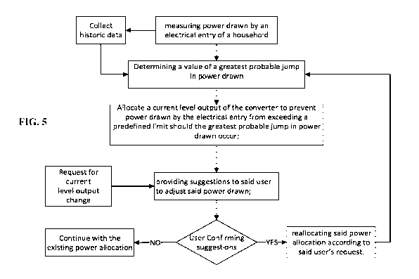
[0048] Figure 5 shows a flowchart of the steps taken in accordance
with one embodiment
of the present disclosure to adjust the power allocation between multiple
loads to comply with a
user request.
[0049] Figure 6 illustrates an example of the apparatus capable of
charging two electric
vehicles having an interface with a display in accordance to one embodiment of
the present
disclosure.
[0050] Figure 7 shows a screenshot of the interface of the converter
showing multiple
options, main menu, of available on the interface in accordance with one
embodiment.
[0051] Figure 8 shows a screen shot of the interface illustrating EV
consumption patterns
for 2 EV vehicles in accordance with one embodiment.
[0052] Figure 9 shows a screenshot of the interface of the converter
illustrating CO2
emission patterns and financial savings for EV users the converter, in
accordance with one
embodiment
[0053] Figure 10 shows a screenshot of the interface of the converter
illustrating weather
conditions, solar panels efficiency and EV charging status in accordance with
one embodiment.
8
CA 03141685 2021-09-15
WO 2020/186363
PCT/CA2020/050380
[0054] Figure 11 shows a screenshot of the interface of the converter
illustrating energy
sources and distribution including charging modes for two different EVs in
accordance to one
embodiment.
[0055] Figure 12 shows a screenshot of the interface of the converter
illustrating a social
networking page for users with similar systems including Ecopoints for each
user and their
ranking.
[0056] Figures 13A shows a screenshot of the interface of the
converter showing total
energy consumption of the household.
[0057] Figure 13B shows screenshot of the interface of the converter
having information
on the charging progress and the EV range.
[0058] Figure 14 shows a screenshot of the interface of the converter
illustrating Ecopoints
and neighborhood ranking of the user in accordance with one embodiment.
[0059] Figure 15 shows a screenshot of the interface of the converter
illustrating customer
support options for the converter.
[0060] Figure 16 shows a screenshot of the interface of the converter
illustrating a
summary of solar panel information, EV charger's information, and climate in
accordance with
one embodiment.
Description
[0061] Reference throughout this specification to "one embodiment,"
"an embodiment,"
or similar language means that a particular feature, structure, or
characteristic described in
connection with the embodiment is included in at least one embodiment of the
present invention.
Thus, appearances of the phrases "in one embodiment," "in an embodiment," and
similar
language throughout this specification may, but do not necessarily, all refer
to the same
embodiment.
[0062] Moreover, the described features, structures, or characteristics of
the invention may
be combined in any suitable manner in one or more embodiments. It will be
apparent to those
skilled in the art that various modifications and variations can be made to
the present invention
without departing from the scope of the invention. Thus, it is intended that
the present invention
cover the modifications and variations of this invention provided they come
within the scope of
the appended claims and their equivalents. Reference will now be made in
detail to the preferred
embodiments of the invention.
9
CA 03141685 2021-09-15
WO 2020/186363
PCT/CA2020/050380
[0063] Throughout this application, the term "EV Level 2 apparatus"
refers to a single-
phase AC EV apparatus and the term "EV Level 3 apparatus" refers to a DC EV
apparatus.
[0064] Figure 1.A illustrates the physical context of an embodiment
in which split single
phase main power is delivered from a utility pole top transformer, as is the
most common type of
electrical power delivery in North America. The transformer receives typically
14.4 kV or 25 kV
single-phase power from a distribution line and the transformer can handle
approximately 50 kVA
to 167 kVA of power delivered as split phase 240 VAC to a small number of
homes or electrical
entries. Each electrical entry is typically configured to handle between 100 A
to 200 A of power
at 240 VAC, namely about 24 kVA to 48 kVA (the common assumption is that 1 kVA
is
equivalent to 1 kW). As shown, the conversion apparatus or device connects to
the network via
the AC connection and can connect to multiple vehicles and/or solar panel.
This could be achieved
thanks to bidirectional (rectifier/inverter) nature of the apparatus which
provides it by the
capability of receiving AC or DC power from one port and providing AC or DC
from other ports.
[0065] The electrical entry typically comprises a usage meter, the
main breaker having a
rating corresponding to the total permitted load (e.g. 100 A or 200 A), and a
panel having circuit
breakers for each household circuit which may be supplied with 240 VAC power
or 120 VAC
power from the split phase 240 VAC input. While most circuit breakers have
capacities of
between 15 A to 30 A, some can be lower (namely 10 A) and some may be larger,
such as 40 A,
for large appliances. In some countries, electrical entries have a lower
capacity, such as 40 A to
60 A, and in countries with 240 VAC in all household circuits, the power is
not a split phase, but
regular single phase 240 VAC (the voltage level used can vary from about 100 V
to 250 V).
[0066] It will be appreciated that embodiments are not restricted to
split single phase 240
VAC power systems and that the embodiments disclosed herein can be adapted to
the power
networks in use that are single or three phases of any existing AC voltage
delivered to the
electrical entry of homes or businesses.
[0067] As illustrated in Figure 1.A, the conversion apparatus is
connected to a circuit
breaker of the main panel through a breaker having a larger current rating,
such as 40 A to 80 A,
although the apparatus disclosed can consume over 100 A if desired. The need
for a circuit breaker
specific to the apparatus is determined by electrical codes. The cable
connecting the apparatus to
the panel is rated for such high current. The connection to the electrical
panel can be a direct fixed
wiring, or a high-voltage socket can be installed and connected to the
electrical panel such that
the apparatus connects to the panel using a cable and plug, for example, those
that are similar to
CA 03141685 2021-09-15
WO 2020/186363
PCT/CA2020/050380
those used for appliances like ovens or clothes dryers. The apparatus is shown
to be connected to
a single load sensor that senses the load drawn by the whole panel including
the apparatus. The
apparatus cable can be a conventional apparatus cable and plug, as is known in
the art.
[0068] In some embodiments, the converter may be a modular multi-
level circuit
benefiting from modular converter circuits uni- or bi-directional. In one
embodiment, the
converter circuit or modules may be multilevel converter topology including
three, five or seven
level topologies. The details of a 5-level Packed U-Cell (PUC 5) which may be
used with the
different embodiments of the present disclosure has been disclosed by the
applicant in the
international PCT patent application having serial number PCT/CA2018/051291
with the
publication number WO/2019/071359.
[0069] As mentioned, the converter may feature the 5-level Packed U-
Cell topology
working in a rectifier mode providing an active rectifier with power factor
correction. The
apparatus has several noteworthy advantages over other types of converters and
features a boost
mode operation which allows supra-AC peak output while reducing or eliminating
input side
current harmonics.
[0070] As shown in Figure 2A, the conversion circuit 100 working in
the rectifier mode
comprises an AC input 105, an inductive filter 110 connected in series with
the AC input 105,
and a 5-level topology circuit 115.
[0071] The inductive filter 110 in this non-limiting example is a 2.5
mH inductor. For a
typical 1 to 3 kW range of power to be delivered (during all charging states
of full power to under-
power), a 1 mH line inductor provided good results which complied with
existing standards. For
higher power ranges, the inductance may be reduced; for example, for high
wattage (e.g. greater
than 2 kW, and preferably greater than 3 kW, and more preferably approximately
5 kW) power
rating, the inductive filter 110 may instead use a 500 H inductor.
Conveniently the present
design allows for a small geometry of the overall power conversion circuit
100, due in part to the
small size of the inductive filter 110. The inductive filter 110 can vary
according to design as
chosen based on the application, power rating, utility voltage harmonics,
switching frequency,
etc. Although the simplest such filter is a single inductor, in an alternative
embodiment the
inductive filter 110 may include a combination of inductor(s) and
capacitor(s), e.g., an (e.g.,
2 mH) inductor connected to a capacitor (e.g., 30 [IF), itself connected to
ground. The choice of
the filter has an impact on the overall size of the design and losses, with a
bigger filter increasing
the size of the overall design and generally incurring more losses.
11
CA 03141685 2021-09-15
WO 2020/186363
PCT/CA2020/050380
[0072] The 5-level circuit comprises a high-voltage capacitor 120, at
least one low-voltage
capacitor 125, two high-voltage power switches 130a, 130b connected between a
first
terminal 135 and respective opposed ends 145a, 145b of the high-voltage
capacitor 120, two
intermediate low-voltage power switches 140a, 140b, each connected between
respective ones of
the two opposed ends 145a, 145b of the high-voltage capacitor 120 and
respective opposed
ends 155a, 155b of the low-voltage capacitor 125, and two terminal low-voltage
power
switches 150a, 150b each connected between a second input terminal 160 and
respective ones of
the opposed ends 155a, 155b of the low-voltage capacitor 125.
[0073] Referring to FIG.2B, there is illustrated a topology 100 for
the 5-level power
converter working in the inverter mode, in accordance with one embodiment. An
AC load 202 is
connected across the first terminal 135 and the second terminal 160, which
correspond to the only
nodes in the circuit where only Switching elements are connected. The voltage
produced between
the first terminal 135 and the second terminal 160 is the inverters output
voltage (V), which is
illustratively a five-level Pulse Width Modulation (PWM) waveform.
[0074] The details of how the PUC 5 circuit functions in the rectifier and
inverter switching
as well as details on the switching states of the PUC 5 has been disclosed by
the applicant in the
international PCT patent application having serial number PCT/CA2018/051291
with the
publication number WO/2019/071359.
[0075] In some embodiments the present disclosure provides a power
management system
for allowing implementation of a user's request. In Figure 1.B, illustrates a
block diagram
showing a power budget controller working with a charger.
[0076] A logging module 1904 stores in a memory at least one
parameter derived from the
current drawn as measured by a sensor 1102, less any power drawn by the
rectifier circuit over
time for various sub-periods within each day. This parameter can be the
greatest probable increase
in non-charging loads for the present time period and the present non-charging
load. Jumps in
load can be derived from one or more appliances turning on. AC motors, such as
heat pump and
air conditioning compressor motors, typically draw at least twice their steady-
state current when
starting. As can be appreciated, the probability of an increase in power drawn
can be within a
desired likelihood, such as within 97% probability.
[0077] An available power predictor calculator 1108 receives the current
drawn value, and
the logging module parameter and provides a maximum charge load value to power
budget
12
CA 03141685 2021-09-15
WO 2020/186363
PCT/CA2020/050380
controller 1906 as a function of a predetermined electrical entry maximum
power load. The
maximum load value for the electrical entry can be set using a user interface.
[0078] The power budget controller 1906 receives the maximum charge
load value and,
from the battery management interface, the desired charge voltage value and
desired charge
current value and provides the control input to the rectifier circuit.
[0079] In one embodiment, the greatest probable increase is
determined based on long-
term observation data. Until such data is acquired, the available power
predictor may behave more
conservatively, and as the certainty increases about the prediction, the
predictor calculator can be
more aggressive.
[0080] In another embodiment, the variations in power consumption are
analyzed to
determine the number and sizes of the main household loads. A behavior pattern
for these loads
is then detected. Loads that are estimated to be on, can only be turned off,
and so they do not
contribute to a risk of increasing the total load. The probability that a load
will turn on is based
on the state of other loads, time of day and time of year. For example, if a
water heater is off,
.. there can be a higher likelihood that it will turn on at any given moment
from 7AM to 8AM due
to water usage than from 11PM to 6AM. In summer, electric heating loads are
unlikely to turn
on, while AC is more likely, and the opposite may hold true in winter. Based
on behavior patterns
and the current estimate of what loads are on, the available power predictor
can predict the greatest
probable immediate increase in power.
[0081] The power budget controller 1906 considers the risk of the greatest
probable
increase in power to determine what power is available to the charger for
consumption, and the
power budget controller causes the rectifier circuit and/or the DC-DC down
converter to adjust
DC power delivered to the EV when the requested power would be too great.
[0082] Furthermore, the power budget controller 1906 can consider
battery degradation
when setting the charging rate. This can involve referencing a predetermined
maximum charge
current or power value. As described below, a user-selected charge
aggressivity level can also be
referenced.
[0083] In one embodiment, when the available power predictor module
1108 forecast that
an increase in power is probable that could risk exceeding the power budget
(entry limit), an
optional sheddable load switch 1922 can be used to prevent a significant load
from drawing power
that can result in exceeding the power budget. This can delay or shift the
added load to avoid
exceeding the power budget of the electric entry. The sheddable load switch
can include a line
13
CA 03141685 2021-09-15
WO 2020/186363
PCT/CA2020/050380
voltage power switch connected between one or more electrical loads and the
electrical panel, for
example, a water heater, to prevent the load from drawing current from the
electrical panel with
the risk that such additional load could exceed the power budget. Preferably,
the load switch
includes a sensor, for example, a current sensor, to measure whether the load
is currently drawing
power. In this way, the power budget controller can detect if the load in
question is drawing
power. The sheddable load switch, when open, can be equipped with sensors to
detect when the
disconnected load is looking to draw power, and in this case, the power budget
controller can then
decide to reconnect the load after reducing DC charging power accordingly.
[0084] Some loads that draw high current include control electronics
that draw a small load
in a standby state, for example, less than about 100 watts. In this case, it
is possible to include
bypass low power AC to the sheddable load while the sheddable load switch is
open. An example
of a low-power AC bypass connection is an isolation transformer configured to
provide about ten
to several tens of watts of power for the electronics of the sheddable load.
When the load switches
on, the sheddable load switch module can detect the draw of power on the load
side of the isolation
transformer and then signal the power budget controller to decide whether to
reduce DC charge
power to allow the sheddable load to be reconnected to full AC power, or
whether DC charging
at the same rate should continue. When DC charging load demand is over and
then permits, the
sheddable load can be reconnected.
[0085] In some embodiments, after system sets up all the limitations
to avoid going over
the budget, a user may still submit a request for a change this setting. For
example, the user may
request to have the EV vehicle be charged faster than what was allowed by the
system. In such
scenarios, the system may use the power drawn increase prediction module 1108
and the data
available in logging module to make suggestions to the user to reduce the
household load and
create possibility of charging the vehicle with a higher charging
aggressivity.
[0086] In one example, the system may use different sensors for different
loads or use a
smart home system to recognize different loads and send the required
suggestions accordingly.
[0087] In some embodiments, the user may need to implement the
changes and confirm
with the converter that the changes have been implemented before the system
changes the
converters power allowance budget in accordance with the user's request.
[0088] In embodiments and for some of the suggestions, the system may be
able to
implement the changes upon on receiving the confirmation from the user. For
example, if
two EVs are charging simultaneously and the user wants to increase the
charging intensity of one
14
CA 03141685 2021-09-15
WO 2020/186363
PCT/CA2020/050380
of them, the converter may suggest reducing the charging intensity of the
other EV and upon
user's confirmation implement such change. In another example, the load may be
a household
appliance like a dryer working with a smart home system. Upon receiving the
confirmation, the
converter may communicate with the smart home system to turn off that specific
load to increase
the charging intensity.
[0089] In one example, the converter may communicate independently
with certain
electrical appliances or as explained before have a sheddable load switch to
reduce the household
load and cope with a user suggestion.
[0090] It would be appreciated by those skilled in the art that the
modules may be
instructions saved on one or more non-transitory computer-readable mediums and
may be
performed by one or more processors. This may include a computer device
connected to the
converter circuit or located in a remote location, such as in cloud
technology, controlling the
converter.
[0091] The embodiment in Figure 3 may include a charging power
program module that
responds to user input to curb the charge rate when the user is not in a rush
to charge the EV.
While EV's can permit fast charging, and embodiments disclosed herein can
allow for charging
with powers of about 25 kVA, battery life can be reduced by repeated fast
charging. Additionally,
the charging power program module may be used to select a time program for
charging, namely
to delay and/or otherwise tailor power consumption in accordance with time-
variable energy costs
and/or the availability of power within the distribution network. The charging
connector can, for
example, provide a user interface for selecting a charge aggressivity level,
namely a variable level
of charge rate when the battery requests high rate charging. Alternatively, a
network interface can
be provided to allow a remote user interface to be used to set charging power
program parameters.
[0092] In one embodiment, the user may request the energy management
system of the
converter to minimize the electrical expense of the household. Again, the
system may make
specific suggestions and ask for the user's confirmation to implement them.
[0093] For example, the energy management system may recognize that
the electricity
tariff is higher at certain times and in order to reduce the energy bill make
suggestions to the user
to reduce some loads during the energy tariff peak hours. In some other
examples, the system
may suggest using a local energy source like a backup battery or EV battery
for household energy
use during the peak hours. This way a backup battery or an EV battery is
charged during the times
CA 03141685 2021-09-15
WO 2020/186363
PCT/CA2020/050380
that the energy tariff is low and may be used during peak hours to reduce the
energy expense of
the household or even help the network during the peak hours of energy
consumption.
[0094] The network interface 1902 can be a conventional data
interface, such as ethernet,
Wi-Fi, etc., associated with a computer. The logging module 1904, power budget
controller 1906,
available power predictor 1908 and the charging power program module 1910 can
be
implemented in software stored in the memory of the computer and executed by a
processor of
the computer to perform the operations as described below.
[0095] Figure 3 shows an embodiment of the apparatus 1100 having a
sensor 1102
connected to the electrical entry. The power drawn prediction module 1108
receives the
information regarding the energy consumption patterns and, in one embodiment,
may store this
information for predicting the maximum power drawn. The power budget module
1106 receives
the prediction as well as the total load from sensor 1102 and the information
from power
converter 1104 and manages the power budget for charging an electric vehicle.
[0096] When a user request fast charging of the vehicle, for example
by touching on the
interface screen shown in Figure 11 at the "FAST/ECO" charging symbol, if
enough power is not
available, the system may provide suggestions as to how the EV charging budget
can be increased.
This may include disconnecting some sheddable load using the sheddable load
switch 1922 or
alternatively asking the user to switch off certain devices having specific
load. The system may
recognize this switching off using the sensors or may ask the user to confirm
it.
[0097] In one embodiment, the apparatus can connect to electric devices and
control them
remotely as to reduce the load. This may be done by user confirmation or set
up to be done
completely automatically.
[0098] Figure 4 shows a scenario in which the apparatus 1100 manages
charging of the
two electric vehicles. In this scenario the power budget controller 1106 has
to manage the
charging budget of two vehicles. When a user requests fast or boost charging
of a vehicle in
addition to options mentioned above, the system may reduce the charging rate
of the other EV or
even use the other EV' s battery to fast charge the battery of EV for which
fast charge has been
requested. An example of device 1100 for charging two vehicles has been shown
in Figure 6.
[0099] Referring to Figure 5 shows an example the steps taken by the
present disclosure
to manage the power allocation of the steps taken by the converter's
management system to make
sure that the power drawn from the electrical entry does not exceed the
predetermined limit. At
least one sensor may be used to measure power drawn by at the entry for
example the household.
16
CA 03141685 2021-09-15
WO 2020/186363
PCT/CA2020/050380
This data may be collected in a historic data collection or logging module.
This data may include
a number of other sensors measuring power consumption at different sections of
the household
or even per each electrical appliance or device. In one example the data may
be fetched from a
smart home system having necessary sensors in place to provide the required
data. In another
example, the converter may work as the smart hub and manage different
appliances and directly
interact with them and measure their consumption and other required
information such as time of
use, frequency of use based on temperature and specific seasonal features,
consumption patterns
based on day of the week, month and season as well as the weather forecast.
Furthermore, a user
may add or remove specific events that may cause an increase or decrease in
consumption into
the logging module or historic data collector. Some specific events may
include, times when
house is empty or a specific event would happen or periods in which the EV(s)
may need to be
fully charged such as in the morning during work days.
[00100] This way the value of the greatest probable jump in the power
drawn would be
calculated. Using this data and the current power drawn the converter
allocates the amount of
power it may provide to different devices such as EV(s), backup battery or any
other load. This
amount may be adjusted by the amount of energy received from a source for
example solar panels,
a local power generator or a backup battery.
[00101] If a user request changes to this power allocation, the
converter power manager
may provide the user with different suggestions and may ask the user the
confirm the suggestion.
This may include asking the user to implement the changes and confirm their
implementation or
asking for permission to implement the changes. If in the other hand the user
does not confirm
the changes the converter may make different suggestions but would continue
working in the
same manner until a confirmation is received.
[00102] In some embodiments, the converter may ask the user for
permission to implement
the same suggestions in similar situations. In another embodiment, the user
may use an interface
to prioritize options and therefore, change the order of the suggestions and
or set up the system
to accept certain suggestions automatically.
[00103] In one embodiment, the system may learn from the accepted
suggestions and
modify the order of the changes based on the prior user confirmation patterns.
In some examples,
the system may use machine learning and AT algorithms known in the art to
modify these
suggestions.
17
CA 03141685 2021-09-15
WO 2020/186363
PCT/CA2020/050380
[00104] Figures 7 to 16 show the interface and how the system can be
managed and
observed by a user using a mobile app, computer or any other end device even
remotely.
[00105] As shown in Figure 7, system may provide information regarding
solar panels, EV
batteries or other batteries connected to the system (backup battery), the
household consumption,
etc. and allow a user manage them accordingly.
[00106] In Figure 8, the system provides the user with information
regarding the charging
of one or more EVs, electricity consumption and other necessary information.
[00107] Figure 9 shows the information provided to a user regarding the
carbon emission
of the energy consumed and the money saved by the user. As in Figure 10, the
interface may
further provide weather forecast information and use them in managing power
allowance. For
example, a warmer day may indicate use of AC by the user or a cloudy day may
indicate low
energy production by the solar panels.
[00108] Figure 11 shows the interface, here as a mobile app, with the
allocation of energy
received and consumed
[00109] In some embodiments, the display in Figure 11 may show one or more
of the
storage capacity of each EV, the percentage of charge of each EV, the charging
schedule for each
EV, e.g., ECU, FAST, or optionally different levels of FAST charging, whether
DC power is
being drawn from an EV to give more power budget for charging another EV,
power contributions
from sources other than the power grid, e.g., solar, storage battery, wind,
etc. the total power
budget, namely in the case of only grid power the main electric entry breaker
value, the greatest
probable jump in power drawn at the electrical entry from household loads,
information about
loads that have been shed to give more EV charging capacity, etc. Furthermore,
upon request a
change in for example charging intensity of an EV vehicle, a suggestion may be
shown on the
display which may be implemented after confirmation of the user or implemented
by the user and
confirmed on the screen.
[00110] Referring to Figure 12 a screenshot of the interface of the
converter illustrating a
social networking page for users with similar systems including Ecopoints for
each user and their
ranking. As illustrated, the users in the neighborhood or community may have
their own profile
and may exchange data including their energy consumption patterns. This may
include neighbors
arranging their energy consumption to avoid any problem with the distribution
network. Also, it
may allow the members to use including buy or sell their energy among each
other depending on
their needs.
18
CA 03141685 2021-09-15
WO 2020/186363
PCT/CA2020/050380
[00111] Figures 13A the interface of the converter showing total energy
consumption of the
household. Figure 13B show screen shot of the interface of the converter
having information on
the charging progress and the EV range. Figure 14 shows the interface of the
converter illustrating
Ecopoints and neighborhood ranking of the user in accordance with one
embodiment. Figure 15
shows a screenshot of the interface of the converter illustrating customer
support options for the
converter. Figure 16 shows a screenshot of the interface of the converter
illustrating a summary
of solar panel information, EV charger's information, and climate in
accordance with one
embodiment.
[00112] In one embodiment, the apparatus may have a calibration mode in
which it may
learn how each electric device may affect the total household load. It may ask
a user to turn the
devices in the house on and off to measure and register its effect on total
load and later make
suggestions accordingly. It may also have sensors at different parts of the
house to measure
consumption and make suggestions accordingly.
[00113] As shown in Figure 6, the apparatus 1100 may have a screen on
it which enable to
have the interface on the apparatus itself.
[00114] Although the above description has been provided with reference
to a specific
example, this was for the purpose of illustrating, not limiting, the
invention.
19