Note: Descriptions are shown in the official language in which they were submitted.
CA 03142190 2021-11-26
WO 2020/247624
PCT/US2020/036115
TITLE
[0001] Fire Protection System for Sloped Combustible Concealed Spaces
Having Hips
CROSS-REFERENCE TO RELATED APPLICATIONS
[0002] This application claims priority from U.S. Provisional Patent
Application No.
62/858,427, titled "Fire Protection System for Sloped Combustible Concealed
Spaces Having Hips",
filed on June 7, 2019, the entire contents of which are incorporated by
reference herein.
BACKGROUND OF THE DISCLOSURE
[0003] The present disclosure relates generally to fire protection, and,
more particularly, to fire
protection systems for use in attics and combustible concealed spaces beneath
pitched roofs,
particularly, those having hips.
[0004] Fire sprinkler systems, and the installation and operation
thereof, are subject to nationally
recognized codes and standards, such as NFPA 13, 13D and 13R, which are
incorporated by
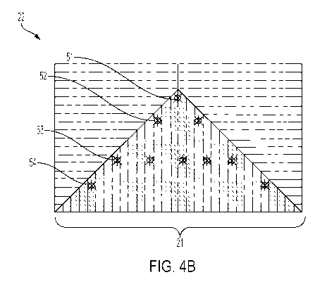
reference herein. NFPA 13 and other standards require the use of equipment and
components that
have been independently tested by a recognized laboratory (e.g. UL or FM) to
identify and verify
their physical characteristics and performance.
[0005] An attic is the normally unoccupied, combustible concealed space
between the ceiling of
the uppermost occupied floor of a building and the pitched roof of the space.
A particular problem
arises with respect to fire protection in attics of buildings where the roof
structures are pitched and
are constructed of wooden joists and rafters or wooden trusses (hereinafter
"structural members");
examples are shown in FIGs. 1A and 1B. Namely, sprinkler selection and
positioning options in an
attic space thus far suffer from delayed activation and inefficient and
exorbitant water consumption.
[0006] The problem becomes more complicated when considering a pitched
roof having "hips,"
an example of which is shown in FIG. 1B. An example of a structure of a hip is
shown in FIG. 2.
Due to the types and arrangement of structural members in such a hip, heat may
spread in a more
complex manner than in a pitched roof without hips (or in the pitched (gable)
portion of a roof with
hips).
[0007] It may, therefore, be desirable to provide fire protection
systems in hip areas of a roof so
as to provide sprinklers within the hip areas in such a way that the
sprinklers are well-positioned in
relation to the fire origin location, that can provide quick response times,
and that have spray
distribution suited for placement near common attic hip structural members,
thereby accomplishing
more efficient fire control.
1
CA 03142190 2021-11-26
WO 2020/247624
PCT/US2020/036115
BRIEF SUMMARY OF THE DISCLOSURE
[0008] Briefly stated, one aspect of the present disclosure may be
directed to a fire protection
system for a hip area of a combustible concealed space. The fire protection
system may comprise
sprinklers arranged in rows, in a direction perpendicular to the slope of the
hip. The spacing of the
sprinklers within a row may have a greater maximum separation distance than a
maximum
separation distance between rows, in a direction parallel to the slope of the
hip (i.e., with respect to a
horizontal direction, e.g., of a bottom of the attic).
[0009] According to a further aspect of the present disclosure, a method
of laying out sprinkler
heads in a hip portion of a roof may involve spacing sprinklers within rows at
a maximum
separation distance greater than a maximum separation distance between
adjacent rows in a
direction parallel to the slope of the hip.
BRIEF DESCRIPTION OF THE DRAWINGS
[0010] The following description of preferred embodiments of the
disclosure will be better
understood when read in conjunction with the appended drawings. It should be
understood,
however, that the disclosure is not limited to the precise arrangements and
instrumentalities shown.
In the drawings:
[0011] FIGS. 1A and 1B shows illustrative examples of structures having
roofs without and with
hips, respectively, according to aspects of the present disclosure;
[0012] FIG. 2 shows an illustrative example of a hip portion of a roof,
according to aspects of
the present disclosure;
[0013] FIG. 3 shows a diagram explaining different orientations, as may
be referred to in aspects
of the present disclosure;
[0014] FIGs. 4A and 4B show conceptual depictions of projections of
respective hip structures
onto horizontal surfaces, according to aspects of the present disclosure; and
[0015] FIGs. 5A and 5B and 6A and 6B show conceptual diagrams of sprinklers
that may be
used according to various aspects of the present disclosure.
DETAILED DESCRIPTION OF THE DISCLOSURE
[0016] Certain terminology is used in the following description for
convenience only and is not
limiting. The words "lower," "bottom," "upper" and "top" designate directions
in the drawings to
which reference is made. The words "inwardly," "outwardly," "upwardly" and
"downwardly" refer
to directions toward and away from, respectively, the geometric center of an
attic space or a
sprinkler, and designated parts thereof, in accordance with the present
disclosure. Unless
2
CA 03142190 2021-11-26
WO 2020/247624
PCT/US2020/036115
specifically set forth herein, the terms "a," "an" and "the" are not limited
to one element, but instead
should be read as meaning "at least one." The terminology includes the words
noted above,
derivatives thereof and words of similar import.
[0017] It should also be understood that the terms "about,"
"approximately," "generally,"
"substantially" and like terms, used herein when referring to a dimension or
characteristic of a
component of the disclosure, indicate that the described
dimension/characteristic is not a strict
boundary or parameter and does not exclude minor variations therefrom that are
functionally
similar. At a minimum, such references that include a numerical parameter
would include variations
that, using mathematical and industrial principles accepted in the art (e.g.,
rounding, measurement or
other systematic errors, manufacturing tolerances, etc.), would not vary the
least significant digit.
[0018] Referring to the drawings in detail, wherein like numerals
indicate like elements
throughout, FIGs. 1A-6B generally show a sprinkler system for an attic or a
combustible concealed
space with a pitched roof having hip sections, according to various aspects of
the present disclosure.
A building or other structure 10 may have an attic or other concealed space 16
(to be referred to
hereinafter as an "attic"). As show in FIG. 1A, an attic 16 may generally be
enclosed from above by
a sloped or pitched roof ("pitched roof' will be used hereinafter) having
opposingly-disposed sloped
sides extending downward and outward from a ridgeline 12 to respective eaves
13. The sides may
be constructed from wooden joists and rafters or wooden trusses (which will,
in the aggregate, be
referred to hereinafter as "structural members"). Eaves 13 may coincide with a
horizontal floor of
the attic 16 or extend beyond the ends of the horizontal floor of the attic
16. The spacing between
adjacent parallel structural members defines a respective channel. Generally,
a channel may, for
example, be between approximately three (3) inches and six (6) inches deep,
but could also be
greater. Also in the example of FIG. 1A, the attic 16 may be enclosed by side
panels 11 a and 1 lb.
[0019] FIG. 1B shows an example of a structure 10 having an attic 16
enclosed by a roof having
a pitched portion and hips 11 a', 1 lb' at the ends, instead of side panels 11
a, 1 lb. Each of hips 11 a',
1 lb' is enclosed by a panel that may extend from an end 14 of ridgeline 12
(end 14 of ridgeline 12
may similarly be referred to as "the apex of the hip"), downwardly and
outwardly, ending in
respective eaves (e.g., eaves 15), which may coincide with or extend beyond an
end of a horizontal
floor of attic 16. The sides of the panels of the hips 11 a', 1 lb' may abut
ends of the respective
downward-sloping sides of the pitched portion of the roof.
[0020] FIG. 2 shows an illustrative example of a support structure 200
of hip 11 a', 1 lb' of a
hipped roof, according to various aspects of the present disclosure. As noted
above, the external
3
CA 03142190 2021-11-26
WO 2020/247624
PCT/US2020/036115
portion of the structure (facing upward and outward) may extend downward and
outward from an
end 14 of ridgeline 12 (not shown).
[0021] Before continuing to describe the support structure 200, it is
useful to discuss a frame of
reference, for descriptive purposes, only. FIG. 3 shows a hip (not labeled).
The hip, shown in solid
lines, may be sloped at some angle s with respect to a horizontal floor (or
other horizontal frame of
reference) of the attic 16, shown in dotted lines. Turning first to the hip
(or outer panel thereof), two
directions may be defined: (a) dpar, a direction parallel to the slope of the
hip; and (b) dpp, a direction
perpendicular to the slope of the hip. In other words, dpar corresponds to a
direction at an upward
slope s with respect to a parallel direction hpar along the horizontal floor,
while dpp corresponds to a
direction that is perpendicular to dpar, and which parallels, in a vertical
projection onto the attic floor,
a direction hpp perpendicular to hpar.
[0022] Returning to FIG. 2, a typical hip support structure 200 may be
composed of two types of
trusses: jack trusses 21 and stepdown trusses 20; it is noted that equivalent
structures may be built
of joists and rafters (not shown). Stepdown trusses 20 may include generally
horizontal pieces that
are spaced apart between the end 14 of the ridgeline to a further generally
horizontal structural
member 23 disposed at a predefined location downslope of end 14 of the
ridgeline, where structural
members 20 and 23 are in a direction perpendicular to the slope of the hip.
The number of stepdown
trusses 20 employed may depend upon the size of the hip 11 a', 1 lb', where a
larger number of
stepdown trusses 20 may be used for larger hips. Jack trusses 21, on the other
hand, may include
.. pieces that are generally parallel to the slope of the hip. In general,
jack trusses 21 may extend four
to fifteen feet from the eaves, again, oriented in a direction generally
parallel to the slope of the hip
11 a', lib', but the jack truss 21 lengths are not thus limited.
[0023] In the foregoing, reference numeral 22 will be used to denote the
outer-facing structure
of hip support structure 200, including the structural members 20, 21 and 23;
for convenience, the
reference numerals 20 and 21, while stated above as corresponding to trusses,
will be used,
interchangeably, to refer to the outer facing structural pieces of the trusses
that are disposed in
perpendicular and parallel directions, respectively, with respect to the slope
of the hip, as well as to
the regions of the hip structure that contain them. The region containing the
stepdown trusses 20
may also be referred to as the "upper hip," while the region containing the
jack trusses 21 may also
be referred to as the "lower hip."
[0024] FIGs. 4A and 4B show two illustrative examples of different hip
structures 22, equipped
with sprinkler systems, according to various aspects of the present
disclosure. The examples of
FIGs. 4A and 4B are shown flat, where the direction of the slope is between
the top and the bottom
4
CA 03142190 2021-11-26
WO 2020/247624
PCT/US2020/036115
(in other words, as if the hip structures were laid flat upon or projected
onto a horizontal surface).
According to another way of stating this, dpar extends in a vertical (or
"north-south") direction on the
page, while dpp extends in a horizontal (or "east-west") direction on the
page.
[0025] Referring first to FIG 4A, a sprinkler system may include
omnidirectional sprinklers 44
arranged in rows 41, 42, 43 perpendicular to the slope of the hip (and thus
parallel to one another).
The omnidirectional sprinklers 44 may be Model GL-SS/RE GL5620, manufactured
by Globe Fire
Sprinkler Corporation ("Globe") and described, for example, in Globe
Publication GFS-650,
"Specific Application Attic Sprinklers," available at www.globesprinkler.com,
and incorporated
herein by reference. Note, however, that the disclosure is not limited to the
use of this specific
omnidirectional sprinkler, and other types may be used. Rows 41 and 42 may be
arranged in a
stepdown portion 20 of structure 22, while row 43 may be arranged in a jack
truss region 21 of
structure 22. Row 41, which may include a single sprinkler 44, but is not thus
limited, may be
located substantially at the apex 14 of the hip 1 la', lib', and row 42 may be
located downslope
from row 21. In general, the sprinklers 44 may be disposed within channels
formed by areas
between trusses; but the disclosure is not thus limited. As noted above, the
stepdown portion 20 and
the jack truss portion 21 may be separated by a horizontal structure member
23, as shown in FIG. 2
(but not shown in the present drawing). It is noted that, while only three
rows of sprinklers 41, 42,
43 are shown in FIG. 4A, more rows may be present, in the upper hip 20, in the
lower hip 21, or
both. This may be dependent, for example, upon the spray patterns/distances of
the sprinklers used.
[0026] Additionally, it is noted that a row of directional sprinklers (not
shown), with spray
patterns directed downslope (i.e., toward the eave), may be employed as a
bottom row within jack
truss portion 21, as a further row, downslope of row 43. This may be used, in
particular, if a
distance to which a given omnidirectional sprinkler 44 is less than the length
of one or more of the
jack trusses 21. An example of such a directional sprinkler is Model GL-SS/DS
GL5621,
manufactured by Globe, and described, e.g., in Globe datasheet, "Specific
Application Attic
Sprinklers," available at www.globesprinkler.com, and incorporated by
reference herein. However,
this is merely an example, and the disclosure is not limited to this
particular sprinkler.
[0027] As a particular example, to which the disclosure is not limited,
the maximum length of
jack trusses 21 in the lower hip may be sixteen feet, and the maximum spread
of an omnidirectional
sprinkler 44 in row 43 may only be twelve feet. In such a case, a further row
(not shown) of
directional sprinklers, as discussed above, may be placed such that the
direction sprinklers spray in a
downslope direction and are sufficient to cover the area of the lower hip not
covered by the spray of
the omnidirectional sprinklers 44 of row 43.
5
CA 03142190 2021-11-26
WO 2020/247624
PCT/US2020/036115
[0028] Within the upper hip 20, as heat rises up the hip 11 a', llb',
the progression of the heat in
a generally upward direction, along the slope of the hip 11 a', lib' may be
slowed by the structure of
the stepdown trusses 20. Due to this structure, heat may roll under the
stepdown trusses 20, which
are perpendicular to the direction of the slope of the hip, and after rolling
under a given stepdown
truss 20, may spread horizontally, prior to rolling under a further stepdown
truss 20. This may
suggest a particular arrangement of sprinklers 44 in the upper hip 20, in
which a maximum spacing
between sprinklers 44 in a direction perpendicular to the slope of the hip is
greater than a maximum
spacing of sprinklers 44 in a direction parallel to the slope of the hip. In
an illustrative example,
maximum spacing in the perpendicular direction may be up to twelve feet
between sprinklers, while
maximum spacing in the parallel direction may be up to ten feet between
sprinklers (i.e., rows of
sprinklers). Note that this is merely an example, and the disclosure is not
thusly limited.
[0029] FIGs. 5A-6B illustrate an example of an omnidirectional sprinkler
44 that may be used,
and which may correspond to Globe Model GL-22/RE GL5620; but it is understood,
once again,
that the disclosure is not limited to any particular omnidirectional
sprinkler. In one non-limiting
example, the sprinkler 44 may be mounted to project upwardly from a water
branch line (either
perpendicularly to the branch line, or at an upward angle relative thereto).
The sprinkler 44 may
include a sprinkler frame 51, a fluid deflector 52, and a thermal trigger
(i.e., heat-sensitive element)
53 supporting a seal assembly/plug 54 to seal the sprinkler 43 in an
unactuated configuration. The
sprinkler frame 51 may define a proximal inlet 51a, a distal outlet 51b, and
an internal water
passageway extending therebetween which defines a sprinkler axis A-A. In the
illustrated example,
the thermal trigger 53 may take the form of a glass-bulb type trigger disposed
and axially aligned
along the sprinkler axis A-A, but the disclosure is not so limited.
[0030] The sprinkler frame 51 may include an at least partially
externally threaded body 55,
defining the proximal inlet 51a, the distal outlet 51b and the internal water
passageway extending
therethrough, which may receive at least a portion of the sealing plug 54. The
body 55 may be
mounted, e.g., threadingly, to a water line branch (not shown) to receive
water therefrom and
through the internal water passageway through the body 55. Two frame arms 56a
may be radially
positioned or diametrically opposed about the body 55 and may extend axially
therefrom toward the
deflector 52. The frame arms 56a may converge toward the sprinkler axis A-A to
terminate at a
terminal end 56b of the sprinkler frame 51 axially aligned along the sprinkler
axis A-A. The
deflector 52 may be mounted upon the terminal end 56b of the sprinkler frame
51.
[0031] A compression screw 57 (shown in FIG. 5B), or the like, may be
used to secure the
thermal trigger 53 upon the sealing plug 54, in a manner well understood by
those of ordinary skill
6
CA 03142190 2021-11-26
WO 2020/247624
PCT/US2020/036115
in the art. The thermal trigger 53, via the compression screw 57, may apply
pressure to the sealing
plug 54 (greater than the opposing water pressure on the sealing plug 54 from
the fluid in the branch
line) to prevent water (from the branch line) from flowing out of the body 55
until the ambient
temperature around the sprinkler 44 reaches the activation temperature, at
which time the thermal
trigger 53 is triggered/activated. Upon activation of the thermal trigger 53,
e.g., shattering of the
glass bulb, the sealing plug 54 may be forced out by the upstream pressurized
water and deflected
away. The water may spray out from the water passageway in the body 55 and may
impact upon the
deflector 52 for distribution thereof in a desired spray pattern according to
the design of the
deflector 52.
[0032] Turning to FIGs. 6A-6B, the deflector 52, in the illustrated
example, may be designed for
spray distribution in a generally elliptical pattern, such as, for example, a
circular pattern. In one
non-limiting example, the pressurized water may be projected by the deflector
52 up to
approximately twenty-four (24) feet in diameter, i.e., twelve (12) feet in
every direction, resulting in
a twelve-foot omnidirectional spray pattern. As shown in FIG. 6A, the
deflector 52 may include a
.. generally circular body 60 defining a diameter D. The deflector 52 may
include a generally circular,
generally flat, mounting aperture 63, for mounting to the terminal end 56b of
the sprinkler frame 51.
The deflector 52 may include a plurality of angularly spaced tines 61 about
the periphery thereof,
which may define a plurality of slots 62 therebetween. In the illustrated
example, the deflector 52
may include eighteen (18) substantially equally dimensioned and substantially
equally spaced tines
61, and eighteen (18) substantially equally dimensioned and substantially
equally spaced slots 62,
but the disclosure is not so limited.
[0033] As shown best in FIG. 6B, the body 60 of the deflector 52 may
include a radially inner
portion 60A, defining the mounting aperture 63 therein, and a concentric
radially outer portion 60B
integral with the inner portion 60A. As shown, the radially outer portion 60B
may be angled
upwardly, i.e., away from the sprinkler frame 51, by an angle 0 relative to
the radially inner portion
60A. In one non-limiting example, the angle 0 may be approximately 5 ,
resulting in a high, top
projection angle of water. Stated differently, in addition to conventional
water distribution at
substantially all downward angles below the deflector 52, the upward
projection angle 0 may enable
the water spray pattern to have a high projection, lofting the water spray
closer to the attic structure
above the sprinkler 44.
[0034] As also shown best in FIG. 6B, at least one pair of diametrically
opposed tines 61A of
the tines 61 of the deflector 52 may be angled downwardly, i.e., toward the
sprinkler frame 51, by an
angle a relative to the radially inner portion 60A of the body 60. In one non-
limiting example, the
7
CA 03142190 2021-11-26
WO 2020/247624
PCT/US2020/036115
angle a may be approximately 600. The sprinkler 44 may be mounted to a water
branch line such
that the tines 61A are oriented substantially transverse to the branch line.
Accordingly, water
sprayed by one sprinkler 44 in a direction substantially transverse to the
branch line may be
deflected away from sprinklers in an adjacent branch line after contacting the
tines 61A.
[0035] It will be appreciated by those skilled in the art that changes
could be made to the various
aspects of the disclosure described above without departing from the broad
inventive concept of this
application. It is understood, therefore, that the disclosure is not limited
to the particular aspects of
the present disclosure, but it is intended to cover modifications within the
spirit and scope of the
present disclosure, as set forth in the appended claims.
8