Note: Descriptions are shown in the official language in which they were submitted.
CA 03142729 2021-12-03
WO 2020/247660 PCT/US2020/036164
SUPPORT FOR ELECTRICAL SWITCH
REFERENCE TO RELATED APPLICATIONS
[0001] This application claims the benefit of co-pending U.S. Provisional
Patent Application
No. 62/857,064, filed June 4, 2019, and U.S. Provisional Patent Application
No. 62/881,675,
filed August 1, 2019. The entire contents of these applications are
incorporated by reference.
BACKGROUND
[0002] This application relates to high-voltage electrical switches, and
particularly to a
support shaft for a high-voltage electrical switch.
SUMMARY
100031 In one independent aspect, a support for a high-voltage electric
switch includes a
housing, a shaft, and an intermediate member positioned between the housing
and the shaft. The
shaft extends at least partially through the housing, and the shaft is
supported for rotation about
an axis. The intermediate member is supported for rotation relative to the
shaft and supported
for rotation relative to the housing.
[0004] In some aspects, the intermediate member is supported for rotation
relative to the
shaft by at least one first bearing, and the intermediate member is supported
for rotation relative
to the housing by at least one second bearing.
[0005] In some aspects, the first bearing includes a first inner race
engaging the shaft and a
first outer race engaging the intermediate member, and the second bearing
includes a second
inner race engaging the intermediate member and a second outer race engaging
the housing.
[00061 In some aspects, the support further includes a retainer positioned
adjacent an end of
the intermediate member.
100071 in some aspects, the retainer retains the second bearing.
100081 In some aspects, the intermediate member is operable to rotate about
the axis while
the shaft and the housing remain stationary.
1
CA 03142729 2021-12-03
WO 2020/247660 PCT/US2020/036164
100091 In another independent aspect, a support for a high-voltage electric
switch includes a
housing, a shaft, and a sleeve positioned between the housing and the shaft.
The shaft extends at
least partially through the housing and the shaft supported for rotation about
an axis. One end of
the shaft is configured to be coupled to a switch member movable between an
open position and
a closed position. The sleeve is rotatable relative to the shaft and rotatable
relative to the
housing.
100101 In some aspects, the support further includes a first bearing
positioned between the
shaft and the sleeve, the first bearing supporting the shaft for rotation
relative to the sleeve.
[0011] In some aspects, the first bearing includes an inner race engaging
the shaft and an
outer race engaging the sleeve.
[0012] In some aspects, the support further includes a second bearing
positioned between the
housing and the sleeve, and the second bearing supports the sleeve for
rotation relative to the
housing.
10013) in some aspects, the second bearing includes an inner race engaging
the sleeve and an
outer race engaging the housing.
[0014] In some aspects, the support further includes a retainer positioned
adjacent an end of
the sleeve.
[0015] In some aspects, a portion of the retainer is configured to be
engaged by a tool to
facilitate manual rotation of the sleeve while the shaft and the housing
remain stationary.
[0016] In some aspects, the retainer abuts a bearing supporting the sleeve
for rotation relative
to the housing.
[0017] In yet another independent aspect, a high-voltage electric switch
includes: a first
electrical terminal configured to be supported on a frame; a second electrical
terminal configured
to be supported on the frame; a conducting member for providing electrical
communication
between the first electrical terminal and the second electrical terminal; and
a shaft assembly
supporting one of the first electrical terminal and the second electrical
terminal for pivoting
2
CA 03142729 2021-12-03
WO 2020/247660 PCT/US2020/036164
movement to move the conducting member between a first position and a second
position. The
conducting member provides electrical communication between the first
electrical terminal and
the second electrical terminal while the conducting member is in the first
position, and electrical
communication between the first electrical terminal and the second electrical
terminal is
inhibited while the conducting member is in the second position. The shaft
assembly includes a
housing, a shaft extending at least partially through the housing, and an
intermediate member
positioned between the housing and the shaft. The shaft is supported for
rotation about an axis.
The intermediate member is supported for rotation relative to the shaft and
supported for rotation
relative to the housing.
100181 In some aspects, the intermediate member is supported for rotation
relative to the
shaft by at least one first bearing, and the intermediate member is supported
for rotation relative
to the housing by at least one second bearing.
100191 In some aspects, the first bearing includes a first inner race
engaging the shaft and a
first outer race engaging the intermediate member, and the second bearing
includes a second
inner race engaging the intermediate member and a second outer race engaging
the housing.
100201 In some aspects, the shaft assembly further includes a retainer
positioned adjacent an
end of the intermediate member.
100211 In some aspects, a portion of the retainer is configured to be
engaged by a tool to
facilitate manual rotation of the intermediate member while the shaft and the
housing remain
stationary.
100221 In some aspects, the retainer abuts a bearing supporting the
intermediate member for
rotation relative to the housing.
100231 Other aspects of the shaft assembly will become apparent by
consideration of the
detailed description and accompanying drawings.
BRIEF DESCRIPTION OF THE DRAWINGS
100241 FIG. 1 is a perspective view of a high-voltage electrical switch in
a closed state.
3
CA 03142729 2021-12-03
WO 2020/247660 PCT/US2020/036164
[0025] FIG. 2 is a perspective view of the high-voltage electrical switch
in an open state.
[0026] FIG. 3 is a perspective view of a shaft assembly.
[0027] FIG. 4 is a cross-sectional view of the shaft assembly of Fig. 3,
viewed along section
4-4
[00281 FIG. 5 is an exploded perspective view of the shaft assembly.
[0029] Before any embodiments are explained in detail, it is to be
understood that the
disclosure is not limited in its application to the details of construction
and the arrangement of
components set forth in the following description or illustrated in the
following drawings. The
disclosure is capable of other embodiments and of being practiced or of being
carried out in
various ways. Also, it is to be understood that the phraseology and
terminology used herein is
for the purpose of description and should not be regarded as limiting. Use of
"including" and
"comprising" and variations thereof as used herein is meant to encompass the
items listed
thereafter and equivalents thereof as well as additional items. Use of
"consisting of" and
variations thereof as used herein is meant to encompass only the items listed
thereafter and
equivalents thereof. Unless specified or limited otherwise, the terms
"mounted," "connected,"
"supported," and "coupled" and variations thereof are used broadly and
encompass both direct
and indirect mountings, connections, supports, and couplings.
DETAILED DESCRIPTION
[0030] Some high-voltage electrical switches (for example, operating at
voltages of 1000 V
or greater) are actuated by rotating one or more of the supports on which the
equipment is
mounted. In addition to facilitating rotation, a switch support must support
the weight of the
parts and support the cantilever loading of the parts without affecting the
switch's ability to
operate satisfactorily. It is also necessary for the support to withstand
weather without
developing rust or other corrosion. In some cases, rust/corrosion can
completely lock bearings
such that an operator must force the switch(es) open with an external tool,
which can be
dangerous at high voltage. Furthermore, most high-voltage switches are
operated (e.g., actuated
to an open state) infrequently¨many switches may be operated once every two
years, and some
4
CA 03142729 2021-12-03
WO 2020/247660 PCT/US2020/036164
are operated even less frequently. Even when operated, the switch may be
rotated only partially
(e.g., rotated about 90 degrees).
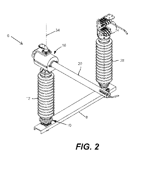
100311 FIGS. 1 and 2 show an exemplary high-voltage electrical switch 6. In
the illustrated
embodiment, the electrical switch 6 is supported on a frame member 8 that may
be connected to
a utility structure (not shown). The switch 6 is supported by a shaft assembly
10 connected to
the frame member 8. A first insulator 12 and a blade support 16 are supported
by the shaft
assembly 10 for pivoting movement relative to the frame member 8. The first
insulator 12 is
positioned between the shaft assembly 10 and the blade support 16. The blade
support 16 is
coupled to an electrically conductive arm or blade 20, which can be
selectively positioned to
engage terminal contacts 24 to close the switch (FIG. 1). The contacts 24 may
be positioned on
top of a second insulator 28. As shown in Fig. 2, the shaft assembly 10
supports the blade
support 16 and blade 20 for pivoting about an axis 34, permitting the blade 20
to move away
from the terminal contacts 24 and open the switch.
100321 FIGS. 3 and 4 illustrate a shaft assembly 10 of a high-voltage
electrical switch. The
shaft assembly 10 includes a support block 42, a first member or main shaft
46, and a second
member or sleeve 50. The support block 42 includes a flange 54 that is secured
to the frame
member 8 (FIG. 1), and also includes a bore 58 (Fig. 4). The main shaft 46
passes through the
bore 58 along the axis 34. One end of the main shaft 46 is secured to a base
62 on which the
insulator 12 (FIG. 1) may be supported.
100331 As shown in FIGS. 4 and 5, the sleeve 50 is positioned within the
bore 58 of the
support block 42, between the main shaft 46 and the support block 42. Stated
another way, the
main shaft 46 passes through an opening 60 of the sleeve 50. The support block
42, the sleeve
50, and the main shaft 46 are each rotatable relative to one another. In
particular, a pair of first
bearings 70 support the main shaft 46 for rotation relative to the sleeve 50,
and a pair of second
bearings 74 support the sleeve 50 for rotation relative to the support block
42. In the illustrated
embodiments, the bearings 70, 74 are roller ball bearings.
100341 As shown in FIG. 5, in the illustrated embodiment, each of the first
bearings 70 may
include a first inner race 70a engaging an outer surface of the main shaft 46,
a first outer race 70b
engaging an inner surface of the sleeve 50, and a plurality of roller elements
72 (e.g., balls)
CA 03142729 2021-12-03
WO 2020/247660 PCT/US2020/036164
positioned between the first inner race 70a and the first outer race 70b. In
some embodiments,
each of the first bearings 70 may include a cage or interior member (not
shown) to maintain the
positions of the balls 72 relative to one another. Each of the second bearings
74 may have a
similar construction¨specifically, each of the second bearings 74 may include
a second inner
race 74a engaging an outer surface of the sleeve 50, a second outer race 74b
engaging an inner
surface of the support block 42, and a plurality of roller elements 76 (e.g.,
balls) positioned
between the second inner race 74a and the second outer race 74b. In some
embodiments, each of
the second bearings 74 may include a cage or interior member (not shown) to
maintain the
positions of the balls 76 relative to one another.
100351 Also, in the illustrated embodiment, a nut 82 threadably engages an
end of the main
shaft 46 opposite the base 62, thereby retaining the first bearings 70 in
engagement between the
sleeve 50 and the main shaft 46. In addition, a retainer 86 is positioned
adjacent one end of the
sleeve 50, and a similar retainer 86 is positioned adjacent an opposite end of
the sleeve 50.
100361 As shown in FIG. 3, each of the retainers 86 can be engaged by a
tool (not shown) to
facilitate rotation of the sleeve 50 while the main shaft 46 and the support
block 42 remain
stationary. In the illustrated embodiment, a flange 88 of the retainer 86 can
be engaged by the
tool. In some embodiments, an adapter plate can be coupled to one or both of
the retainers 86 to
permit a technician to rotate the sleeve 50 by using an insulated operating
pole or similar device.
Also, in some embodiments, an assembly could connect the sleeves 50 of
multiple shaft
assemblies 10 to actuate the sleeves 50 at the same time.
100371 Rotation of the sleeve 50 cycles or exercises the bearings 70, 74
without requiring the
switch 6 to change position. The rotation assists in performing maintenance on
the bearings 70,
74 and the overall assembly. In addition, the actuation allows a technician to
detect if any of the
bearings 70, 74 have seized, rather than requiring the switch be physically
opened (and avoiding
the need to wait for an opportunity when the switch can be opened) to
determine that the
bearings have failed.
100381 Although aspects have been described in detail with reference to
certain preferred
embodiments, variations and modifications exist within the scope and spirit of
one or more
6
CA 03142729 2021-12-03
WO 2020/247660 PCT/US2020/036164
independent aspects as described. Various features and advantages are set
forth in the following
claims.
7