Note: Descriptions are shown in the official language in which they were submitted.
CA 03143243 2021-12-10
WO 2020/251449 PCT/SE2020/050566
1
ARRANGEMENT OF A DRIVE WHEEL FOR AN ENDLESS TRACK OF A
TRACKED VEHICLE
TECHNICAL FIELD
The present invention relates to an arrangement of a drive wheel for an
endless track of a tracked vehicle. The present invention also relates to a
tracked vehicle comprising drive wheels having such an arrangement.
BACKGROUND
Tracked vehicles may be equipped with opposite track assemblies. Each track
assembly comprises an endless track arranged to run over a set of wheels
comprising a drive wheel, a tension wheel and a set of road wheels there
between.
A drive wheel may be equipped with a hub member and an inner drive sprocket
and an outer drive sprocket connected to the respective side of the hub
member.
Wear on drive wheels may be relatively large, depending on environment in
which such tracked vehicles are used. When using endless tracks of rubber,
exchange of drive wheels need to be performed in a workstation, where the
each drive sprocket of the drive wheel needs to be removed. Thus, when the
tracked vehicle is not in access of a workstation and there is a need to
exchange a drive wheel due to wear on drive sprockets a problematic situation
may occur.
There is a need for providing an arrangement of a drive wheel for an endless
track which facilitates maintenance of the drive wheel.
CA 03143243 2021-12-10
WO 2020/251449 PCT/SE2020/050566
2
OBJECTS OF THE INVENTION
An object of the present invention is to provide an arrangement of a drive
wheel
for an endless track which facilitates maintenance of the drive wheel.
A further object of the present invention is to provide a vehicle comprising
such
.. an arrangement.
SUMMARY OF THE INVENTION
These and other objects, apparent from the following description, are achieved
by an arrangement and a vehicle, as set out in the appended independent
claims. Preferred embodiments of the arrangement are defined in appended
dependent claims.
According to the invention the objects are achieved by an arrangement of a
drive wheel for an endless track of a tracked vehicle. The drive wheel
comprises a hub member and a drive sprocket member attached to the hub
.. member. Said drive sprocket member comprises a ring shaped drive sprocket
having a set of teeth arranged around the circumference of said drive
sprocket.
Said drive sprocket is configured to engage with said endless track. Said
drive
sprocket member further comprises a support member for said drive sprocket.
Said drive sprocket is divided into at least two arc shaped drive sprocket
parts,
each drive sprocket part, in a non engaged state of a drive sprocket part with
respect to said endless track, being configured to be exchangeable. Said
arrangement comprises a guiding configuration comprising a first guiding
member circumferentially distributed around the support member and a
second guiding member circumferentially distributed around the respective
drive sprocket part for facilitating reassembling the drive sprocket.
By thus providing such a guiding configuration, radial control in connection
to
assembling/reassembling of the drive sprocket is obtained. By means of such
a first guiding member of the support member and second guiding member of
CA 03143243 2021-12-10
WO 2020/251449 PCT/SE2020/050566
3
the respective drive sprocket part, the drive sprocket and hence each drive
sprocket part may be directed to a correct radial position relative to the
support
member during assembly/reassembly of drive sprocket parts to the support
member. Thus, hereby maintenance of the drive wheel is facilitated. Further,
such a guiding configuration will take up radial load on the drive wheel when
the drive wheel is assembled on the tracked vehicle. Such a guiding
configuration may also facilitate manufacturing of the drive wheels. By thus
providing such a divided drive sprocket, maintenance of the drive wheel is
facilitated in that radial control in connection to assembling/reassembling of
the drive sprocket is obtained, wherein a sprocket part may be assembled
independently of how it is rotated relative to the support member, thus
facilitating reducing vehicle downtime.
According to an embodiment of the arrangement one of said first and second
guiding members is a recess and the other of said first and second guiding
members is a protrusion configured to engage with said recess. Hereby
guiding of the sprocket parts when assembling/reassembling the sprocket
parts on the support member is facilitated. Hereby correct radial position of
the
respective sprocket part relative to the support member is facilitated.
According to an embodiment of the arrangement said recess is a
circumferentially running groove and said protrusion is a circumferentially
running ridge. Hereby guiding of the sprocket parts when
assembling/reassembling the sprocket parts on the support member is
facilitated. Hereby correct radial position of the respective sprocket part
relative to the support member is facilitated. By thus having the protrusion
and
recess running circumferentially a sprocket part may be assembled
independently of how it is rotated relative to the support member.
According to an embodiment of the arrangement one of said first and second
guiding members is arranged on one side of the support member and the other
of said first and second guiding members is opposingly arranged on the
respective drive sprocket part. Hereby guiding of the sprocket parts when
CA 03143243 2021-12-10
WO 2020/251449 PCT/SE2020/050566
4
assembling/reassembling the sprocket parts on the support member is
facilitated. Hereby correct radial position of the respective sprocket part
relative to the support member is facilitated.
According to an embodiment of the arrangement each arc shaped drive
sprocket part, where the drive sprocket is divided, has a first end portion
and
a second end portion, each end portion of a drive sprocket part being
configured to connect with an end portion of another drive sprocket part so as
to form said drive sprocket, said arrangement further comprising a connecting
configuration comprising a first connecting member arranged in connection to
an end portion of a drive sprocket part and a second connecting member
arranged in connection to an end portion of another drive sprocket part
intended to connect with the first connecting member for facilitating
reassembling the drive sprocket. By thus providing such a connecting
configuration, radial and axial control in
connection to
assembling/reassembling of the drive sprocket is obtained. By means of such
a first and second connecting members at end portions of drive sprocket parts
the drive sprocket parts may be easily directed to a correct position relative
to
each other during assembly/reassembly of drive sprocket parts to the support
member so that the drive sprocket parts of the drive sprocket are correctly
aligned relative to each other when applied onto the support member of the
drive wheel.
According to an embodiment of the arrangement one of said first and second
connecting members is a recess and the other of said first and second
connecting members is a protrusion configured to engage with said recess.
Hereby guiding of the sprocket parts relative to each other when
assembling/reassembling the sprocket parts on the support member is
facilitated. Hereby correct alignment both radially and axially of the
sprocket
parts relative to each other is facilitated.
According to an embodiment of the arrangement said drive wheel comprises
an outer drive sprocket member arranged on the outer side of the hub member
CA 03143243 2021-12-10
WO 2020/251449 PCT/SE2020/050566
and an inner drive sprocket member arranged on the inner side of the hub
member.
According to the invention the objects are achieved by a tracked vehicle
comprising an arrangement as set out herein.
5
DESCRIPTION OF THE DRAWINGS
For a better understanding of the present invention reference is made to the
following detailed description when read in conjunction with the accompanying
drawings, wherein like reference characters refer to like parts throughout the
several views, and in which:
Fig. 1 schematically illustrates a side view of a tracked vehicle according to
an
embodiment of the present disclosure;
Fig. 2 schematically illustrates a side view of a track assembly of a tracked
vehicle according to an embodiment of the present disclosure;
Fig. 3a-b schematically illustrates cross sectional views of the track
assembly
in fig. 2 showing a drive wheel for the endless track of the track assembly
according to an embodiment of the present disclosure;
Fig. 4 schematically illustrates a perspective view of the drive wheel and
portion of the track in fig. 3b according to an embodiment of the present
disclosure;
Fig. 5 schematically illustrates a perspective view of a part of the drive
wheel
in fig. 4 according to an embodiment of the present disclosure;
Fig. 6a schematically illustrates a cross sectional view of a the part of the
drive
wheel in fig. 5 according to an embodiment of the present disclosure;
CA 03143243 2021-12-10
WO 2020/251449 PCT/SE2020/050566
6
Fig. 6b schematically illustrates a cross sectional view of a portion of the
part
of the drive wheel in fig. 6a according to an embodiment of the present
disclosure;
Fig. 7 schematically illustrates a perspective view of an arc shaped drive
sprocket part according to an embodiment of the present disclosure;
Fig. 8a schematically illustrates a side view of the arc shaped drive sprocket
part in fig. 7 according to an embodiment of the present disclosure;
Fig. 8b schematically illustrates a front view of the arc shaped drive
sprocket
part in fig. 7 according to an embodiment of the present disclosure; and
Fig. 8c schematically illustrates a rear view of the arc shaped drive sprocket
part in fig. 7 according to an embodiment of the present disclosure.
DETAILED DESCRIPTION
Herein the term "rubber" in relation to "rubber track" refers to any elastic
material such as rubber, elastomers or combinations of rubber and elastomers.
According to an aspect of the present disclosure an arrangement of a drive
wheel for an endless track of a tracked vehicle is provided. The arrangement
is an arrangement for facilitating exchange and reassembling of a drive
sprocket of a drive wheel of a tracked vehicle. The arrangement is an
arrangement for facilitating exchange and reassembling of a respective drive
sprocket part of the drive wheel.
Such a tracked vehicle may comprise a right track assembly and a left track
assembly for driving the vehicle. Such a tracked vehicle may alternatively be
a tracked vehicle with a single track assembly. Each track assembly may
comprise a drive wheel, a tension wheel, a set of road wheels and an endless
track arranged to run over said wheels. The endless track of the respective
CA 03143243 2021-12-10
WO 2020/251449 PCT/SE2020/050566
7
track assembly may be arranged to be driven and hence rotated by means of
said drive wheel. The tracked vehicle may comprise drive means for driving
said drive wheels. The drive means may be any suitable drive means such as
one or more internal combustion engines and/or one or more electric
machines.
The endless track of the respective track assembly may have any suitable
configuration and be of any suitable material. The endless track of the
respective track assembly may according to an aspect of the present
disclosure be a rubber track. The endless track of the respective track
assembly may according to an aspect of the present disclosure be a steel
track.
The drive wheel comprises a hub member and a drive sprocket member
attached to the hub member. Said drive sprocket member comprises a ring
shaped drive sprocket having a set of teeth arranged around the circumference
of said drive sprocket.
Said drive sprocket is configured to engage with said endless track. Said set
of teeth of said drive sprocket are configured to engage with said endless
track.
Said drive sprocket member further comprises a support member for said drive
sprocket. Said support member of the drive wheel may be configured to be
attached to the hub member. Said support member of the drive wheel may be
configured to be attached to the hub member by means of joint members, e.g.
screw joint members.
Said drive sprocket may be configured to be attached to the support member.
Said drive sprocket may be configured to be attached to the support member
by means of joint members, e.g. screw joint members.
Said drive sprocket is divided into at least two arc shaped drive sprocket
parts,
each drive sprocket part, in a non engaged state of a drive sprocket part with
respect to said endless track, being configured to be exchangeable.
CA 03143243 2021-12-10
WO 2020/251449 PCT/SE2020/050566
8
When said drive wheel is arranged at the tracked vehicle a portion of the
teeth
of the drive sprocket may be engaged with the endless track. When said drive
wheel is arranged at the tracked vehicle a portion of the teeth of one drive
sprocket part may be engaged with the endless track, and another drive
sprocket part may be at a rotated position of the drive wheel so that it is
not
engaged with the endless track and may thus be removed and exchanged.
The drive wheel may then be rotated to another rotated position of the drive
wheel so that another drive sprocket part is rotated so that it is not engaged
with the endless track and may thus be removed and exchanged.
Said arrangement comprises a guiding configuration comprising a first guiding
member circumferentially distributed around the support member and a
second guiding member circumferentially distributed around the respective
drive sprocket part for facilitating reassembling the drive sprocket. Said
arrangement thus comprises a guiding configuration comprising a first guiding
member circumferentially distributed around the support member and a
second guiding member circumferentially distributed around the respective
drive sprocket part for facilitating reassembling one or more of the drive
sprocket parts to the support member. Said arrangement comprises a guiding
configuration comprising a first guiding member circumferentially distributed
around the support member and a second guiding member circumferentially
distributed around the respective drive sprocket part for facilitating
assembling
the drive sprocket and hence one or more of drive sprocket parts of the drive
sprocket. A drive sprocket part being assemble/reassembled may be a new
drive sprocket part replacing a damaged/broken drive sprocket part or the
same drive sprocket part that was removed, which e.g. has been repaired.
Said first guiding member circumferentially distributed around the support
member and second guiding member circumferentially distributed around the
respective drive sprocket part are configured so that radial control in
connection to assembling/reassembling of the drive sprocket is obtained. Said
first guiding member circumferentially distributed around the support member
CA 03143243 2021-12-10
WO 2020/251449 PCT/SE2020/050566
9
and second guiding member circumferentially distributed around the
respective drive sprocket part are configured so that the drive sprocket and
hence each drive sprocket part may be directed to a correct radial position
relative to the support member during assembly/reassembly of drive sprocket
parts to the support member.
According to an aspect of the present disclosure one of said first and second
guiding members is a recess and the other of said first and second guiding
members is a protrusion configured to engage with said recess.
According to an aspect of the present disclosure said recess is a
circumferentially running groove and said protrusion is a circumferentially
running ridge. According to an embodiment said circumferentially running
groove has a certain cross sectional shape, e.g. U-shape, V-shape, arc-shape
or the like, and said circumferentially running ridge has a cross sectional
shape, e.g. rectangular shape, triangular shape, arc shape or the like,
configured to at least partly fit in and thus engage with the groove and thus
having an essentially corresponding reversed shape.
According to an aspect of the present disclosure one of said first and second
guiding members is arranged on one side of the support member and the other
of said first and second guiding members is opposingly arranged on the
respective drive sprocket part. According to an embodiment of the
arrangement one of said first and second guiding members is arranged on one
side of the support member and the other of said first and second guiding
members is arranged on a side of the drive sprocket, i.e. arranged on a side
of the respective drive sprocket part.
According to an aspect of the present disclosure one of said first and second
guiding members comprises a set of circumferentially distributed
openings/holes and the other of said first and second guiding members
comprises a set of circumferentially distributed taps engagable with said
openings/holes.
CA 03143243 2021-12-10
WO 2020/251449 PCT/SE2020/050566
According to an aspect of the present disclosure each arc shaped drive
sprocket part, where the drive sprocket is divided, has a first end portion
and
a second end portion. Each end portion of a drive sprocket part may be
configured to connect with an end portion of another drive sprocket part so as
5 to form said drive sprocket.
According to an aspect of the present disclosure said arrangement further
comprises a connecting configuration comprising a first connecting member
arranged in connection to an end portion of a drive sprocket part and a second
connecting member arranged in connection to an end portion of another drive
10 sprocket part intended to connect with the first connecting member for
facilitating reassembling the drive sprocket. Said arrangement thus comprises
a connecting configuration comprising a first connecting member arranged in
connection to an end portion of a drive sprocket part and a second connecting
member arranged in connection to an end portion of another drive sprocket
part intended to connect with the first connecting member for facilitating
reassembling the drive sprocket to the support member.
Said first connecting member arranged in connection to an end portion of a
drive sprocket part and a second connecting member arranged in connection
to an end portion of another drive sprocket part are configured such that
radial
.. and axial control in connection to assembling/reassembling of the drive
sprocket is obtained.
Said first connecting member arranged in connection to an end portion of a
drive sprocket part and a second connecting member arranged in connection
to an end portion of another drive sprocket part are configured such that the
drive sprocket parts may be easily directed to a correct position relative to
each
other during assembly/reassembly of drive sprocket parts to the support
member so that the drive sprocket parts of the drive sprocket are correctly
aligned relative to each other when applied onto the support member of the
drive wheel.
CA 03143243 2021-12-10
WO 2020/251449 PCT/SE2020/050566
11
According to an aspect of the present disclosure one of said first and second
connecting members is a recess and the other of said first and second
connecting members is a protrusion configured to engage with said recess.
According to an embodiment said recess has certain cross sectional shape,
e.g. U-shape, V-shape, arc-shape or the like, and said protrusion has a cross
sectional shape, e.g. rectangular shape, triangular shape, arc shape or the
like, configured to at least partly fit in and thus engage with the recess and
thus
having an essentially corresponding reversed shape. According to an
embodiment said recess is a groove and said protrusion is a ridge, said groove
and ridge respectively having an extension essentially parallel to the axial
extension of an imaginary axis of its respective arc shaped drive sprocket
part.
According to an embodiment said recess is a blind hole and said groove is a
tap configured to fit in said hole.
According to an aspect of the present disclosure said drive wheel comprises
an outer drive sprocket member arranged on the outer side of the hub member
and an inner drive sprocket member arranged on the inner side of the hub
member.
For a tracked vehicle with a single track assembly having a single drive
wheel,
the drive wheel comprises a hub member and a drive sprocket member
attached to the hub member. In this case the drive wheel may comprise a first
drive sprocket member arranged on one side of the hub member and a second
drive sprocket member arranged on the opposite side of the hub member. The
hub member hereby has a first side configured to face out from one side of the
vehicle and an opposite second side configured to face out from the opposite
side of the vehicle, when the drive wheel is mounted to the single track
assembly of the vehicle.
Fig. 1 schematically illustrates a side view of a tracked vehicle V according
to
an embodiment of the present disclosure.
The vehicle V is according to the disclosure in fig. 1 a military vehicle.
CA 03143243 2021-12-10
WO 2020/251449 PCT/SE2020/050566
12
The tracked vehicle V comprises a vehicle body B, which according to an
aspect of the present disclosure comprises the chassis of the vehicle V and
bodywork.
The tracked vehicle V comprises a right track assembly Ti and a left track
.. assembly for driving the vehicle V, the right track assembly being shown in
fig.
1. Each track assembly comprises a drive wheel DW, a tension wheel TW, a
set of road wheels RW and an endless track E arranged to run over said
wheels. Here the drive wheel DW is arranged in the front, the tension wheel
TW is arranged in the back and the road wheels RW are arranged between
the drive wheel DW and the tension wheel TW. The tracked vehicle according
to the present disclosure may however have track assemblies with any suitable
arrangement of drive wheel, tension wheel and road wheels. According to an
aspect of the present disclosure the tension wheel may be arranged in the
front, the drive wheel arranged in the back and the road wheels arranged there
between.
The endless track E of the respective track assembly is arranged to be driven
and hence rotated by means of said drive wheel DW. The tracked vehicle V
comprises a drive means, not shown, for driving said drive wheels DW. The
drive means may be any suitable drive means such as an internal combustion
engine and/or an electric machine.
The endless track of the respective track assembly may have any suitable
configuration and be of any suitable material. The endless track E of the
respective track assembly is according to an aspect of the present disclosure
a rubber track. The endless track of the respective track assembly may
according to an aspect of the present disclosure be a steel track.
Fig. 2 schematically illustrates a side view of a track assembly Ti of a
tracked
vehicle according to an embodiment of the present disclosure. The track
assembly Ti comprises a drive wheel DW and an endless track E arranged to
CA 03143243 2021-12-10
WO 2020/251449 PCT/SE2020/050566
13
run over said drive wheel DW. The track assembly Ti may comprise tension
wheel and road wheels, not shown.
Fig. 3a-b schematically illustrates cross sectional views A-A of the track
assembly Ti in fig. 2 showing a drive wheel DW for the endless track E of the
track assembly Ti according to an embodiment of the present disclosure. Fig.
4 schematically illustrates a perspective view of the drive wheel DW and
portion of the track E in fig. 3b according to an embodiment of the present
disclosure. Fig. 5 schematically illustrates a perspective view of a part of
the
drive wheel in fig. 4 according to an embodiment of the present disclosure.
The drive wheel DW has a centre axis Z, see fig. 3a-b. The drive wheel DW
comprises a hub member H. The hub member H is configured to be operably
engaged with the drive axle of the drive means of the tracked vehicle and
configured to be rotated by the drive means. The hub member H is thus
arranged to rotate about the centre axis Z, see fig. 3a-b.
The hub member H has according to this embodiment spokes. The hub
member according to the present disclosure may have any suitable
configuration. The drive means may according to an aspect of the present
disclosure, not shown, be arranged in connection to the drive wheel such that
the drive means, e.g. an electric machine, at least partly is accommodated
within the periphery of the drive wheel, the drive means axle essentially
coaxially coinciding with the centre axis Z of the drive wheel.
According to an aspect of the present disclosure said hub member H has a
first side H1 and an opposite second side H2. According to the embodiment of
the present disclosure illustrated in e.g. fig. 3a-b, for a tracked vehicle
having
right track assembly and a left track assembly for driving the vehicle, the
first
side constitutes a front side H1 configured to face out from the vehicle, i.e.
side
of the vehicle, and the opposite second side constitutes a rear side H2 is
configured to face towards the vehicle.
CA 03143243 2021-12-10
WO 2020/251449 PCT/SE2020/050566
14
According to an aspect of the present disclosure, the hub member H has a
front side H1 and an opposite rear side H2, see fig. 3a-b. The front side H1
is
configured to face out from the vehicle and the rear side H2 is configured to
face towards the vehicle.
According to an aspect of the present disclosure said drive wheel DW
comprises a first drive sprocket member Si arranged on the first side H1 of
the hub member H and an opposite second drive sprocket member S2
arranged on the opposite second side H2 of hub member H. According to the
embodiment of the present disclosure illustrated in e.g. fig. 3a-b, for a
tracked
vehicle having right track assembly and a left track assembly for driving the
vehicle, the first drive sprocket member Si constitutes an outer drive
sprocket
member Si arranged on the front side H1 of the hub member H and the second
drive sprocket member S2 constitutes an inner drive sprocket member S2
arranged on the rear side H2 of the hub member H.
According to an aspect of the present disclosure said drive wheel DW
comprises an outer drive sprocket member Si arranged on the front side H1
of the hub member H and an inner drive sprocket member S2 arranged on the
rear side H2 of the hub member H.
The respective drive sprocket member Si, S2 comprises a ring shaped drive
sprocket 10. Each ring shaped drive sprocket 10 has a set of teeth 12 arranged
around the circumference of the drive sprocket 12. The drive sprocket 10 of
the respective drive sprocket member Si, S2 is configured to engage with said
endless track E. Said teeth 12 of said drive sprocket 10 of the respective
drive
sprocket member Si, S2 is configured to engage with said endless track E.
Said teeth are 12 configured to engage with an endless track of the tracked
vehicle.
The respective drive sprocket member Si, S2 comprises a support member
20 for the respective drive sprocket 10. According to this embodiment, the
outer drive sprocket member Si comprises a support member 20 for the drive
CA 03143243 2021-12-10
WO 2020/251449 PCT/SE2020/050566
sprocket 10 of said outer drive sprocket member Si. According to this
embodiment, the inner drive sprocket member S2 comprises a support
member for the drive sprocket 10 of said inner drive sprocket member S2.
The support member 20 of the respective drive sprocket member Si, S2 has,
5 according to the embodiment in fig. 2 and 3, a ring shaped configuration.
The
support member 20 of the respective drive sprocket member Si, S2 has an
outer side 20a and an opposite inner side 20b.
The support member 20 of the respective drive sprocket member Si, S2 has
a front side 20c and an opposite rear side 20d.
10 The front side 20c of the support member 20 of the outer drive sprocket
Si is
configured to face away from the front side H1 of the hub member H when
attached to the hub member H. The front side 20c of the support member 20
of the inner drive sprocket S2 is configured to face away from the rear side
H2
of the hub member H when attached to the hub member H.
15 The rear side 20d of the support member 20 of the outer drive sprocket
Si is
configured to face towards the front side H1 of the hub member H when
attached to the hub member H. The rear side 20d of the support member 20
of the inner drive sprocket S2 is configured to face towards the rear side H2
of
the hub member H when attached to the hub member H.
The support member 20 of the respective drive sprocket Si, S2 is configured
to be attached to the hub member. The support member 20 of the respective
drive sprocket Si, S2 is, according to an aspect of the present disclosure, a
single portion configured to be attached to the hub member H and configured
to receive drive sprocket 10 of the respective drive sprocket member Si, S2.
The support member 20 of the outer drive sprocket Si is configured to be
attached to the hub member H in connection to the first side H1, here front
side
H1 of the hub member H. The support member 20 of the inner drive sprocket
CA 03143243 2021-12-10
WO 2020/251449 PCT/SE2020/050566
16
S2 is configured to be attached to the hub member H in connection to the
second side H2, here rear side H2 of the hub member H.
The drive sprocket 10 of the respective drive sprocket member Si, S2 has an
outer side 10a and an opposite inner side 10b.
The drive sprocket 10 of the respective drive sprocket member 51, S2 has a
front side 10c and an opposite rear side 10d.
The front side 10c of the drive sprocket 10 of the outer drive sprocket member
Si is configured to face away from the front side 20c of the support member
20 of the outer drive sprocket member Si when attached to the support
member 20. The front side 10c of the drive sprocket 10 of the inner drive
sprocket member S2 is configured to face away from the front side 20c of the
support member 20 of the inner drive sprocket member S2 when attached to
the support member 20 of the inner drive sprocket member S2. The teeth 12
of the drive sprocket 10 are configured to protrude from the front side 10c.
The rear side 10d of the drive sprocket 10 of the outer drive sprocket member
Si is configured to face towards the front side 20c of the support member 20
of the outer drive sprocket member Si when attached to the support member
20. The rear side 10d of the drive sprocket 10 of the inner drive sprocket
member S2 is configured to face towards the front side 20c of the support
member 20 of the inner drive sprocket member S2 when attached to the
support member 20.
The drive sprocket 10 of the respective drive sprocket member Si, S2 of the
drive wheel DW comprises a base portion 14. The base portion 14 has an arc
shape. The base portion 14 comprises said outer side 10a, opposite inner side
.. 10b, said front side 10c and said rear side 10d. The teeth 12 are
configured to
project from said base portion 14 on the outer side 10a and from the front
side
10c.
CA 03143243 2021-12-10
WO 2020/251449 PCT/SE2020/050566
17
The drive sprocket 10 of the respective drive sprocket member Si, S2 of the
drive wheel DW comprises a base portion 14.
According to this embodiment the drive sprocket 10 of the respective drive
sprocket member 51, S2 comprises a set of fastening members 16 arranged
around the inner side 10b of the respective ring shaped drive sprocket 10, see
fig. 5 showing the set of fastening members 16 for the outer drive sprocket
member Si. The respective fastening member 16 comprises or is arranged to
receive a bolt joint J for attaching the drive sprocket 10 to the support
member
20 of the respective drive sprocket member 51, S2 of the drive wheel DW. The
number of bolt joints for attaching the drive sprocket to the support member
of
the respective drive sprocket member may be any suitable number and may
vary depending on e.g. configuration of the tracked vehicle.
According to this embodiment the fastening members 16 are attached to
corresponding fastening members 26 of the support member 20 by means of
.. said bolt joints J. Thus, the support member 20 of the respective drive
sprocket
member 51, S2 comprises a set of fastening members 26 arranged around
the inner side 20b of the respective ring shaped support member 20.
The drive sprocket 10 of the respective drive sprocket member 51, S2 of the
drive wheel DW is according to this embodiment divided into two arc shaped
drive sprocket parts 10A, 10B, a first arc shaped drive sprocket part 10A and
a second arc shaped drive sprocket part 10B, see fig. 5. Depending on e.g.
number of teeth the respective arc shaped drive sprocket part may be the
same article or different articles. In fig. 3a-b and fig. 4 the first drive
sprocket
part 10A is visible. The first arc shaped drive sprocket part 10A and the
second
arc shaped drive sprocket part 10B are configured to be connected to each
other at its respective end portions. When the arc shaped drive sprocket parts
10A, 10B are connected, said drive sprocket 10 is formed. When the arc
shaped drive sprocket parts 10A, 10B are connected a first border B1 is formed
where the first end portion of the respective drive sprocket parts 10A, 10B
are
CA 03143243 2021-12-10
WO 2020/251449 PCT/SE2020/050566
18
connected and a second border B2 formed where the second end portion of
the respective drive sprocket parts 10A, 10B are connected, see fig. 5.
Each drive sprocket part 10A, 10B, in a non engaged state of a drive sprocket
part with respect to said endless track E, is configured to be exchangeable.
Thus, the drive sprocket with the respective drive sprocket part 10A, 10B is
configured such that, in a certain rotational position of the drive wheel DW,
one
of the drive sprocket parts will not be engaged with the endless track E,
which
facilitates removing that drive sprocket part. By then rotating the endless
track
E so that the drive wheel DW is rotated to a certain new rotational position,
the
.. other drive sprocket part will not be engaged with the endless track and my
thus also be removed.
In fig. 3a the first drive sprocket part 10A of the drive sprocket 10 of the
outer
drive sprocket member Si is being removed from the support member 20. In
fig. 3b the first drive sprocket part 10A of the drive sprocket 10 of the
inner
drive sprocket member S2 is being removed from the support member 20.
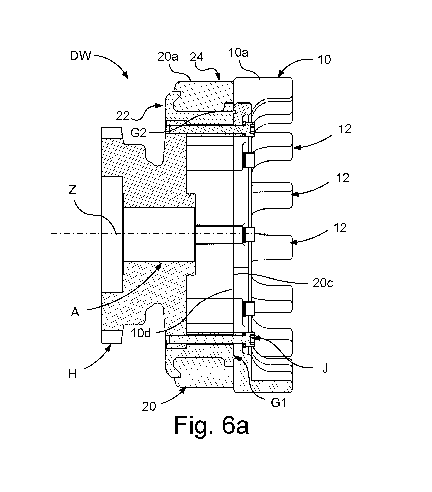
Fig. 6a schematically illustrates a cross sectional view of a the part of the
drive
wheel DW in fig. 5 according to an embodiment of the present disclosure; and
fig. 6b schematically illustrates a cross sectional view of a portion of the
part
of the drive wheel DW in fig. 6a according to an embodiment of the present
disclosure.
The drive axle A of the drive wheel DW is illustrated in fig. 6a. The drive
shaft
A is configured to rotate the drive wheel DW about the axis Z by means of the
drive arrangement of the vehicle.
Fig. 7 schematically illustrates a perspective view of an arc shaped drive
.. sprocket part according to an embodiment of the present disclosure; fig. 8a
schematically illustrates a side view of the arc shaped drive sprocket part in
fig. 7 according to an embodiment of the present disclosure; fig. 8b
schematically illustrates a front view of the arc shaped drive sprocket part
in
fig. 7 according to an embodiment of the present disclosure; and fig. 8c
CA 03143243 2021-12-10
WO 2020/251449 PCT/SE2020/050566
19
schematically illustrates a rear view of the arc shaped drive sprocket part in
fig. 7 according to an embodiment of the present disclosure.
Each arc shaped drive sprocket part 10A, 10B has, as mentioned above a first
end portion 10e and a second end portion 10f configured to provide said
borders B1, B2 when the drive sprocket parts forming the drive sprocket 10
are attached on the support member 20 of the drive wheel DW. The first end
portion 10e and the second end portion 10f of the arc shaped drive sprocket
10A is illustrated in fig. 7 and fig. 8b-c.
When the arc shaped drive sprocket parts 10A, 10B are connected a first
.. border B1 is formed where the first end portion of the respective drive
sprocket
parts 10A, 10B are connected and a second border B2 formed where the
second end portion of the respective drive sprocket parts 10A, 10B are
connected, see fig. 5.
The present disclosure comprises an arrangement of a drive wheel. The
arrangement is an arrangement for facilitating exchange and reassembling of
the drive sprocket 10 of the drive wheel DW. The arrangement is an
arrangement for facilitating exchange and reassembling of the respective drive
sprocket part 10A, 10B of the drive wheel DW.
Said arrangement comprises a guiding configuration G1, G2 for facilitating
exchange and reassembling of the drive sprocket 10 and hence the respective
drive sprocket part 10A, 10B of the drive wheel DW.
Said guiding configuration G1, G2 comprises a first guiding member G1
circumferentially distributed around the support member 20.
Said guiding configuration G1, G2 comprises a second guiding member G2
circumferentially distributed around the respective drive sprocket part and
hence the drive sprocket 10 for facilitating reassembling the drive sprocket
10.
According to an embodiment of the arrangement one of said first and second
guiding members G1, G2 is a recess and the other of said first and second
CA 03143243 2021-12-10
WO 2020/251449 PCT/SE2020/050566
guiding members G1, G2 is a protrusion configured to engage with said recess.
According to the embodiment disclosed with reference to e.g. fig. 6a-b the
first
guiding member G1 arranged on the respective support member 20 is a
protrusion G1. According to the embodiment disclosed with reference to e.g.
5 fig. 6a-b the second guiding member G2 arranged on the respective drive
sprocket 10 is a recess G2.
According to this embodiment of the arrangement said protrusion G1 is a
circumferentially running ridge G1 running around the front side 20c of the
support member 20.
10 Thus, according to this embodiment of the arrangement said protrusion G1
is
configured to run in an arc shaped track, i.e. an arc shaped ridge G1 on the
front side 20c of the support member 20, following the ring shaped extension
of the support. According to this embodiment of the arrangement said
protrusion G1 is configured to run in a circle, i.e. an circular ridge G1 on
the
15 front side 20c of the support member 20, following the ring shape of the
support
member 20.
According to this embodiment of the arrangement said recess G2 is a
circumferentially running groove G2 running around the rear side 10d of the
drive sprocket 10, i.e. the rear side 10d of the respective drive sprocket
part
20 10A, 10B, see also fig. 8a and fig. 8c. Thus, according to this
embodiment of
the arrangement said recess G2 is configured to run in an arc shaped track,
i.e. an arc shaped groove G2 on the rear side 10d of the respective drive
sprocket part 10A, 10B, following the arc shaped extension of the respective
drive sprocket part 10A, 10B. The groove G2 of the respective drive sprocket
part 10A, 10B is configured to run in an arc shaped track such that, when the
sprocket parts 10A, 10B are connected so that the ring shaped drive sprocket
10 with the first and second borders B1, B2 is formed, the grooves G2 are
configured to coincide so that a circular groove G2 is formed on the rear side
of the drive sprocket 10.
CA 03143243 2021-12-10
WO 2020/251449 PCT/SE2020/050566
21
The recess G2, e.g. groove G2, may have any suitable cross section
configured to receive said protrusion G2 of the support member 20. The recess
G2 may have any suitable polygonal cross section. The recess G2 may
according to an embodiment have an arc shaped cross section. The recess
G2 may according to an embodiment have a U-shaped cross section. The
recess G2 may according to an embodiment have a V-shaped cross section.
The recess G2 may according to an embodiment have a rectangular-shaped,
e.g. square-shaped, cross section.
The protrusion G1, e.g. ridge G1, may have any suitable cross section
configured to receive the recess G2 of the respective sprocket part 10A, 10B
of the sprocket 10 having a corresponding cross section. The ridge G2 may
have any suitable polygonal cross section. The ridge G1 may according to an
embodiment have an arc shaped cross section configured to at least partly fit
into a recess G2 of the respective sprocket part 10A, 10B having a
corresponding arc-shaped cross section. The ridge G1 may according to an
embodiment have a rectangular cross section configured to at least partly fit
into a recess G2 of the respective sprocket part 10A, 10B having a
corresponding U-shaped cross section. The ridge G1 may according to an
embodiment have a triangular cross section configured to at least partly fit
into
a recess G2 of the respective sprocket part 10A, 10B having a corresponding
V-shaped cross section.
According to an embodiment of the arrangement, not shown, one of said first
and second guiding members comprises a set of circumferentially distributed
openings/holes and the other of said first and second guiding members
comprises a set of circumferentially distributed taps engagable with said
openings/holes.
As mentioned above the first end portion 10e and a second end portion 10f of
the respective arc shaped drive sprocket part 10A, 10B, see fig. 7 and fig. 8b-
c, is configured to provide said borders B1, B2, see fig. 5, when the drive
CA 03143243 2021-12-10
WO 2020/251449 PCT/SE2020/050566
22
sprocket parts forming the drive sprocket 10 are attached on the support
member 20 of the drive wheel DW.
The first end portion 10e and a second end portion 10f of the respective arc
shaped drive sprocket part 10A, 10B thus provides the borders where the drive
sprocket 10 is divided.
The arrangement for facilitating exchange and reassembling of the respective
drive sprocket part 10A, 10B of the drive wheel DW may according to an aspect
of the present disclosure further comprise a connecting configuration Cl, C2
comprising a first connecting member Cl arranged in connection to an end
portion of a drive sprocket part and a second connecting member C2 arranged
in connection to an end portion of another drive sprocket part intended to
connect with the first connecting member Cl for facilitating reassembling the
drive sprocket.
According to an embodiment of the arrangement one of said first and second
connecting members Cl, C2 is a recess and the other of said first and second
connecting members Cl, C2 is a protrusion configured to engage with said
recess. According to an embodiment said recess has certain cross sectional
shape, e.g. U-shape, V-shape, arc-shape or the like, and said protrusion has
a cross sectional shape, e.g. rectangular shape, triangular shape, arc shape
or the like, configured to at least partly fit in and thus engage with the
recess
and thus having an essentially corresponding reversed shape. According to an
embodiment said recess is a groove and said protrusion is a ridge, said groove
and ridge respectively having an extension essentially parallel to the axial
extension of an imaginary axis of its respective arc shaped drive sprocket
part.
According to an embodiment said recess is a blind hole and said groove is a
tap configured to fit in said hole.
Fig. 8b schematically illustrates an exemplary embodiment of the present
disclosure in which the first arc shaped drive sprocket part 10A has a first
connecting member Cl arranged in connection to the first end portion 10e and
CA 03143243 2021-12-10
WO 2020/251449 PCT/SE2020/050566
23
a second connecting member C2 arranged in connection to the second end
portion 10f. The first connecting member Cl is according to this example a
recess Cl and the second connecting member C2 is according to this example
a protrusion C2.
With the first arc shaped drive sprocket part 10A having a connecting
configuration Cl, C2 according to fig. 8b, the second arc shaped sprocket part
10B would then be arranged with a connecting configuration Cl, C2 with a first
connecting member Cl arranged in connection to the first end portion 10e in
the shape of a recess Cl and a second connecting member C2 in the shape
of a protrusion C2. Hereby the recess Cl at the first end portion 10e of the
first
drive sprocket part 10A would engage with the protrusion C2 at the second
end portion 10f of the second drive sprocket part 10B and the protrusion C2 at
the second end portion 10f of the first drive sprocket part 10A would engage
with the recess Cl at the first end portion 10e of the second drive sprocket
part
10B, thus forming the drive sprocket 10 when assembled.
Alternatively, not shown, the first arc shaped drive sprocket part 10A could
have a first connecting member Cl, e.g. a recess, in connection to both the
first end portion 10e and the second end portion 10f, wherein the second arc
shaped drive sprocket part 10B would have a second connecting member C2,
e.g. a protrusion, in connection to both the first end portion 10e and the
second
end portion 10f for engagement with the first connecting members Cl.
Fig. 6a schematically illustrates a cross sectional view of a the part of the
drive
wheel DW in fig. 5, showing the hub member H, a support member 20 and a
drive sprocket 10 according to an embodiment of the present disclosure.
According to this embodiment the support member 20 has a base part 22 and
a peripheral part 24. The base part 22 comprises according to this embodiment
the second guiding member G2 in the shape of said circumferential running
ridge G2 running on the front side 20c of the support member 20. The
peripheral part 24 is according to this embodiment configured to surround and
run around the base part 22. The peripheral part 24 comprises according to
CA 03143243 2021-12-10
WO 2020/251449 PCT/SE2020/050566
24
this embodiment the outer side 20a of the support member 20. By thus dividing
the support member 20 into a base part 22 and a peripheral part 24 said parts
22, 24 may be made of different materials.
According to an embodiment the base part 22 is made of steel and the
peripheral part 24 is made of a plastic material. Hereby the weight of the
drive
wheel DW may be reduced. Further, improved durability may be obtained in
certain environmental conditions. This may also lead to less packaging of snow
and ice in winter conditions.
The foregoing description of the preferred embodiments of the present
invention has been provided for the purposes of illustration and description.
It
is not intended to be exhaustive or to limit the invention to the precise
forms
disclosed. Obviously, many modifications and variations will be apparent to
practitioners skilled in the art. The embodiments were chosen and described
in order to best explain the principles of the invention and its practical
applications, thereby enabling others skilled in the art to understand the
invention for various embodiments and with the various modifications suited to
the particular use contemplated.
Below some general aspects of the arrangement and the tracked vehicle
according to the present disclosure are listed.
Aspect 1: An arrangement A of a drive wheel DW for an endless track E of
a tracked vehicle V, the drive wheel DW comprising a hub member H and a
drive sprocket member Si, S2 attached to the hub member H, said drive
sprocket member 51, S2 comprising a ring shaped drive sprocket 10 having a
set of teeth 12 arranged around the circumference of said drive sprocket 10,
said drive sprocket 10 being configured to engage with said endless track E,
said drive sprocket member 51, S2 further comprising a support member 20
for said drive sprocket 10, said drive sprocket 10 being divided into at least
two
arc shaped drive sprocket parts 10A, 10B, each drive sprocket part 10A, 10B,
in a non engaged state of a drive sprocket part with respect to said endless
CA 03143243 2021-12-10
WO 2020/251449 PCT/SE2020/050566
track E, being configured to be exchangeable, wherein each arc shaped drive
sprocket part 10A, 10B, where the drive sprocket 10 is divided, has a first
end
portion 10e and a second end portion 10f, each end portion of a drive sprocket
part being configured to connect with an end portion of another drive sprocket
5 part so as to form said drive sprocket 10, said arrangement A further
comprising a connecting configuration Cl, C2 comprising a first connecting
member Cl arranged in connection to an end portion of a drive sprocket part
and a second connecting member C2 arranged in connection to an end portion
of another drive sprocket part intended to connect with the first connecting
10 member Cl for facilitating reassembling the drive sprocket 10.
Aspect 2: An arrangement according to aspect 1, wherein one of said first
and second connecting members Cl, C2 is a recess Cl and the other of said
first and second connecting members C2 is a protrusion C2 configured to
engage with said recess Cl.
15 Aspect 3: An arrangement according to aspect 1 or 2, wherein said
arrangement A comprising a guiding configuration G1, G2 comprising a first
guiding member G1 circumferentially distributed around the support member
20 and a second guiding member G2 circumferentially distributed around the
respective drive sprocket part 10A, 10B for facilitating reassembling the
drive
20 sprocket 10.
Aspect 4: An arrangement according to any of aspects 1-3, wherein one of
said first and second guiding members G1, G2 is a recess G2 and the other of
said first and second guiding members G1, G2 is a protrusion G1 configured
to engage with said recess G2.
25 Aspect 5: An arrangement according to aspect 4, wherein said recess G2
is
a circumferentially running groove and said protrusion G1 is a
circumferentially
running ridge.
Aspect 6: An arrangement according to any of aspects 3-5, wherein one of
said first and second guiding members G1, G2 is arranged on one side 10c of
CA 03143243 2021-12-10
WO 2020/251449 PCT/SE2020/050566
26
the support member (20) and the other of said first and second guiding
members G1, G2 is opposingly arranged on the respective drive sprocket part
10A, 10B.
Aspect 7: An arrangement according to any of aspects 1-6, said drive wheel
DW comprising an outer drive sprocket member Si arranged on the outer side
of the hub member H and an inner drive sprocket member S2 arranged on the
inner side of the hub member H.
Aspect 8: A vehicle V comprising an arrangement according to any of
aspects 1-7.