Note: Descriptions are shown in the official language in which they were submitted.
IMAGING REFLECTOR ANTENNA SYSTEM AND METHOD
[001] This paragraph has been left intentionally blank.
SUMMARY
[002] An antenna system includes: an antenna, the antenna configured to
combine
the feed elements to form a high gain element beam (HGEB), the system further
configured to combine the HGEBs to form a large coverage beam; and a feed
array
configured to transfer a signal to the antenna, the feed array being defocused
from a focal
plane of the antenna by a defocus distance, the feed array comprising a number
N of feed
elements. For example, the signal comprises a radio frequency (RF) signal.
[003] A method for beam scanning includes: using an antenna system, the
system
comprising a single reflector imaging antenna (SRIA), and using a feed array
comprising
a number N of feed elements, the feed array configured to transfer a signal to
the antenna,
the feed array being defocused from a focal plane of the antenna by a defocus
distance,
the antenna configured to combine the feed elements to form a number M of
medium gain
element beams (MGEBs), the antenna further configured to combine the MGEBs to
form
a number J of high gain element beams (HGEBs), and the system further
configured to
combine all or some number of MGEBs to form a large coverage beam, using the N
feed
elements and the antenna, forming N single element beams; combining the N
single
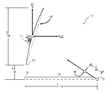
element beams, using the N feed elements; forming M MGEBs in a first level
beam
1
Date Recue/Date Received 2023-03-14
CA 03143457 2021-12-14
WO 2021/006937 PCT/US2020/027905
2
forming network (BFN); and combining the MGEBs in a second level BFN to create
the
large coverage beam.
[004] A method for beam scanning includes: using an antenna system, the
system
comprising an antenna, the antenna comprising a single reflector imaging
antenna
(SRIA), the system further comprising a two-axis gimbal mechanism, the system
further
comprising a feed array configured to transfer a signal to the antenna, the
feed array
being defocused from a focal plane of the antenna by a defocus distance, the
feed array
comprising a number N of feed elements, the antenna configured to combine the
feed
elements to form a number J of high gain element beam (HGEBs), the system
further
configured to combine the HGEBs to form a large coverage beam, performing
precise
electronic scanning over a first region, generating the J HGEBs and the large
coverage
beam; and performing coarse mechanical scanning over a second region using the
two-
axis gimbal mechanism by keeping the feed array fixed and gimballing the
reflector
antenna, wherein the second region is larger than the first region, generating
J second
level beams and a large coverage beam.
[005] An antenna system includes: a single reflector imaging antenna
(SRIA), the
antenna configured to combine the feed elements to form a high gain element
beam
(HGEB), the system further configured to combine the HGEBs to form a large
coverage
beam; a two-axis gimbal mechanism placed on a back of the SRIA antenna; and a
feed
array configured to transfer a signal to the antenna, the feed array being
defocused from
a focal plane of the antenna by a defocus distance, the feed array comprising
a number
N of feed elements, the feed array further comprising a number N of
polarizers, the feed
array further comprising a number N of filters, the feed array further
comprising a number
N of amplifiers, the amplifiers configured to pass the signal to a first level
beamforming
network (BFN), the first level BFN configured to combine the feed elements to
form a
number M of medium gain element beams (MGEBs), the feed array further
comprising M
post-first level BFN amplifiers, the feed array further comprising N local
oscillator/mixers,
the feed array further comprising a second level digital BFN configured to
combine the
MGEBs to form a number J of outgoing high gain element beams (HGEBs), the
system
further configured to combine the HGEBs to form the large coverage beam.
[006] An
antenna system includes: a dual reflector imaging antenna (DRIA), the
system comprising a main reflector, the system further comprising a sub-
reflector; and a
feed array configured to transfer a signal to the antenna, the feed array
being defocused
from a focal plane of the antenna by a defocus distance, the feed array
configured to
receive a number N of feed elements, the feed array passing the N signals
through a first
level beamforming network (BFN), the feed array further comprising a number N
of
attenuators, the feed array further comprising a number N of phase shifters,
the feed array
further comprising a number 3N of amplifiers, the feed array further
comprising a number
N of triplexers, the feed array further comprising a number 3N of polarizers,
the feed array
further comprising a number 3N of filters, the feed array further comprising a
number N
of amplifiers, the system further configured to combine the beams to
simultaneously form
a large global coverage beam and a high gain scanning spot beam.
[006a] According to an aspect, there is provided an antenna system comprising:
a
single reflector imaging antenna (SRIA); and a feed array comprising a number
N of feed
elements, the feed array configured to transfer a signal to the antenna, the
feed array
being defocused from a focal plane of the antenna by a defocus distance, the
3
Date Recue/Date Received 2023-03-14
antenna configured to combine the feed elements to form high gain element
beams
(HGEBs), the system further configured to combine the HGEBs to form a large
coverage
beam, the system further configured to perform precise electronic scanning
over a small
region, the system further configured to perform coarse mechanical scanning
over a
larger region keeping the feed array fixed and gim balling the reflector
antenna using the
two-axis gimbal mechanism.
[006b]According to another aspect, there is provided a method for beam
scanning,
comprising: using an antenna system, the system comprising a single reflector
imaging
antenna (SRIA), and using a feed array comprising a number N of feed elements,
the
feed array configured to transfer a signal to the antenna, the feed array
being defocused
from a focal plane of the antenna by a defocus distance, the antenna
configured to
combine the feed elements to form a number M of medium gain element beams
(MGEBs),
the antenna further configured to perform precise electronic scanning over a
first region,
the antenna further configured to combine the MGEBs to form a number J of high
gain
element beams (HGEBs), and the system further configured to combine all or
some
number of MGEBs to form a large coverage beam, using the N feed elements and
the
antenna, forming N single element beams; combining the N single element beams,
using
the N feed elements; forming M MGEBs in a first level beam forming network
(BFN);
combining the MGEBs in a second level BEN to create the large coverage beam;
and
performing coarse mechanical scanning over a second region using the two-axis
gimbal
mechanism by keeping the feed array fixed and gimballing the reflector
antenna, wherein
the second region is larger than the first region, generating J second level
beams and a
large coverage beam.
3a
Date Recue/Date Received 2023-03-14
[006c] According to a further aspect, there is provided a method for beam
scanning,
comprising: using an antenna system, the system comprising a single reflector
imaging
antenna (SRIA), the system further comprising a two-axis gimbal mechanism, the
system
further comprising a feed array configured to transfer a signal to the
antenna, the feed
array being defocused from a focal plane of the antenna by a defocus distance,
the feed
array comprising a number N of feed elements, the antenna configured to
combine the
feed elements to form a num ber J of high gain element beam (HGEBs), the
system further
configured to combine the HGEBs to form a large coverage beam, performing
precise
electronic scanning over a first region, generating the J HGEBs and the large
coverage
beam; and performing coarse mechanical scanning over a second region using the
two-
axis gimbal mechanism by keeping the feed array fixed and gimballing the
reflector
antenna, wherein the second region is larger than the first region, generating
J second
level beams and a large coverage beam.
[006d] According to yet another aspect, there is provided an antenna system
comprising: a single reflector imaging antenna (SRIA), the antenna configured
to combine
feed elements to form a high gain element beam (HGEB), the system further
configured
to combine the HGEBs to form a large coverage beam; a two-axis gimbal
mechanism
placed on a back of the SRIA antenna; and a feed array configured to transfer
a signal to
the antenna, the feed array being defocused from a focal plane of the antenna
by a
defocus distance, the feed array comprising a number N of feed elements, the
feed array
further comprising a number N of polarizers, the feed array further comprising
a number
N of filters, the feed array further comprising a number N of amplifiers, the
amplifiers
configured to pass the signal to a first level beamforming network (BFN), the
first level
3b
Date Recue/Date Received 2023-03-14
BFN configured to combine the feed elements to form a number M of medium gain
element beams (MGEBs), the feed array further comprising M post-first level
BFN
amplifiers, the feed array further comprising N local oscillator/mixers, the
feed array
further comprising a second level digital BFN configured to combine the MGEBs
to form
a number J of outgoing high gain element beams (HGEBs) the system configured
to
perform precise electronic scanning over a small region, the system further
configured to
perform coarse mechanical scanning over a larger region keeping the feed array
fixed
and gim balling the reflector antenna using the two-axis gimbal mechanism.
[006e] According to yet a further aspect, there is provided an antenna system
comprising: a dual reflector imaging antenna (DRIA), the system comprising a
main
reflector, the system further comprising a sub-reflector; and a feed array
configured to
transfer a signal to the antenna, the feed array being defocused from a focal
plane of the
antenna by a defocus distance, the feed array configured to receive a number N
of feed
elements, the feed array passing the N signals through a first level
beamforming network
(BFN), the feed array further comprising a number N of attenuators, the feed
array further
comprising a number N of phase shifters, the feed array further comprising a
number 3N
of amplifiers, the feed array further comprising a number N of triplexers, the
feed array
further comprising a number N of polarizers, the feed array further comprising
a number
3N of filters, the feed array further comprising a number 3N of amplifiers,
the system
further configured to combine the beams to simultaneously form a large global
coverage
beam and a high gain scanning spot beam.
3c
Date Recue/Date Received 2023-03-14
DESCRIPTION OF THE DRAWINGS
[007]
The accompanying drawings provide visual representations which will be used
to more fully describe various representative embodiments and can be used by
those
3d
Date Recue/Date Received 2023-03-14
CA 03143457 2021-12-14
WO 2021/006937 PCT/US2020/027905
4
skilled in the art to better understand the representative embodiments
disclosed herein
and their inherent advantages. In these drawings, like reference numerals
identify
corresponding elements.
[008] Figure 1 is a drawing of components of a single reflector imaging
antenna
(SRIA) system.
[009] Figure 2 is a drawing of a feed array usable with a single reflector
imaging
antenna (SRIA) system.
[0010] Figure 3 is a graph plotting measured return loss of the integrated
dual-band
feed array against percentage bandwidth for the SRIA system.
[0011] Figure 4 is a graph plotting measured on-axis axial ratio of the
integrated dual-
band feed array against the percentage bandwidth for the SRIA system.
[0012] Figure 5A is a graph plotting directivity of the integrated dual-
band feed array
against azimuth angle.
[0013] Figure 5B is a drawing of a single feed assembly usable with
embodiments of
the invention.
[0014] Figure 6 is a graph plotting directivity of an SRIA system using an
integrated
dual-band feed array against azimuth angle for computed element beam patterns
for the
SRIA system for the low frequency band using a single feed per beam with no
beam-
forming network.
[0015] Figure 7 is a graph plotting directivity of an SRIA system using an
integrated
dual-band feed array against azimuth angle for synthesized medium gain element
beam
(MGEB) element beam patterns for the SRIA system for the low frequency band
using a
first level beam-forming network comprising 7-element beams in the azimuth
plane.
CA 03143457 2021-12-14
WO 2021/006937 PCT/US2020/027905
[0016] Figure 8 is a graph plotting directivity of an SRIA system using an
integrated
dual-band feed array against azimuth for synthesized MGEBs forming exemplary
high
gain multiple beams (HGMBs) for the low frequency band.
[0017] Figure 9 is a graph plotting directivity of an SRIA system using an
integrated
dual-band feed array against azimuth angle for synthesized MGEBs forming
exemplary
HGMBs for the low frequency band when the beams are electronically scanned to
0.5
degrees away from a boresight direction in the azimuth plane.
[0018] Figure 10 is a graph plotting directivity of a SRIA system using an
integrated
dual-band feed array against azimuth for synthesized element beam patterns for
HGMBs
for the high frequency band and a larger coverage beam.
[0019] Figure 11 is an illustration of a hybrid scanning method.
[0020] Figure 12 is a schematic diagram of components of the SRIA system.
[0021] Figures 13A-13B are a set of two graphs plotting directivity of the
SRIA system
using an integrated dual-band feed array against azimuth in two frequency
bands for the
HGEB when all 37 feed elements are used to illuminate the reflector using a
first level
beamforming network (BFN) and a second level BFN.
[0022] Figure 14 is a drawing of components of a dual reflector imaging
antenna
(DRIA) system.
[0023] Figure 15 is a schematic diagram of components of the Dual Reflector
Imaging
Antenna (DRIA) system.
[0024] Figure 16 is a graph 1600 plotting Effective Isotropic Radiated
Power (EIRP)
against theta angle of spot beams in the boresight direction formed by a DRIA
system
from a geo-stationary satellite.
CA 03143457 2021-12-14
WO 2021/006937 PCT/US2020/027905
6
[0025] Figure 17 is a graph plotting EIRP against theta angle of spot beams
when the
beam is scanned to -6 degrees away from the boresight direction formed by a
DRIA
system from a geo-stationary satellite.
[0026] Figure 18 is a flow chart of a method for beam scanning.
[0027] Figure 19 is a flow chart of a method for beam scanning.
DETAILED DESCRIPTION
[0028] An antenna system allowing on-orbit beam reconfiguration is provided
using
high gain multiple beams (HGMB) employing imaging reflector antennas. Beam
scanning
over global coverage is achieved using a combination of precise electronic
scanning over
a small region and coarse mechanical scanning over a larger global coverage.
This
method provides significant improvements in gain relative to prior art methods
that employ
element beams and can simultaneously provide both HGMBs and wide area coverage
beams with low cost payloads.
[0029] Embodiments of the invention provide high gain multiple overlapping
spot
beams by combining all feed elements of an imaging reflector antenna with
optimized
excitations to form high gain element beams (HGEBs). The HGEBs are then
combined
to form one or more of a larger coverage beam and an adapted beam capable of
mitigating one or more jammers.
[0030] The system combines a number N of low-gain element beams into a
number
M of medium gain element beams (MGEBs). The system then combines the M MGEBs
into a number J of high-gain element beams. The combination of the N feed
elements
CA 03143457 2021-12-14
WO 2021/006937 PCT/US2020/027905
7
increases antenna gains of the N beams by approximately 2.0 dB to 3.0 dB
relative to the
prior art. A hybrid scanning method combines electronic scanning over a
smaller region
and mechanical scanning over a larger region using a two-axis gimbal
mechanism,
keeping the feed array fixed and gimballing the reflector antenna.
[0031] The N feed element excitations (both amplitude and phase) are used
to scan
the set of N element beams to a desired scan location in a N element beam
cluster. The
beams are then combined to form M MGEBs first and then are combined again
using the
MGEBs to form J HGEBs. A single antenna provides both high gain multiple beams
and
a theater coverage beam.
[0032] Figure 1 is a drawing of components of a single reflector imaging
antenna
(SRIA) system 100. The system 100 comprises a single offset reflector antenna
110. For
example, the single offset reflector antenna 110 comprises a single offset
paraboloid
reflector antenna 110. Depicted are orthogonal coordinate axes x 111, y 112
(extending
perpendicularly out of the page), and z 113. The antenna 110 has a diameter D
114. The
antenna 110 has a focal point 115. Optionally, the system further comprises a
two-axis
gimbal mechanism 117 and uses a hybrid scanning method.
[0033] The system 100 further comprises a feed array 120 configured to
exchange
power with the antenna 110. For example, the feed array comprises seven
elements. The
feed array 120 is positioned at a feed array-focus distance h 125 from the
focal point 115.
The focal point 115 lies on an axis 130. For example, and as depicted, the
focal point 115
lies on a generally paraboloid axis 130. The axis 130 has a first end at the
focal point 115.
The axis 130 has a second end 131 at a point below a near end 132 of the
antenna 110
CA 03143457 2021-12-14
WO 2021/006937 PCT/US2020/027905
8
and having the same x coordinate as the near end of the antenna 110. The axis
130 has
a focal length F 133.
[0034] The feed array 120 is defocused from the focal plane by a defocus
distance H
135 equal to a distance along the x axis from the focal point 115 to the near
end 132 of
the antenna 110. According to embodiments of the invention, the feed array 120
is moved
away from the focal plane in order to improve adjacent beam overlap so that
the system
can use more elements for each beam. This causes defocusing of the element
beam from
the feed array 120, which allows element beams to broaden, improving adjacent
beam
overlap. An array of feed elements is used to form each beam. Using a first
level
beamforming network, this improves beam efficiency to approximately 50% from
14%.
Then a second level of beamforming is used to improve beam efficiency to
approximately
80%.
[0035] Exemplary antenna geometrical parameters are D = 129A, focal length
F/D =
1.2, and defocus distance H = 51 65A, where A is the wavelength at mid-band of
low
frequency. The feed array is defocused from the focal plane by a defocus
distance. As a
result of the defocusing, the element beams broaden, depending on the defocus
distance,
resulting in increased overlap between adjacent beams. Element beams typically
have
lower gain due to non-optimal illumination on the reflector. By combining a
number of
element beams, a certain number of medium gain element beams (MGEB) are
formed.
Subsequently, a certain number of high gain element beams (HGEB) are formed
and
these HGEBs are then used to form either an adapted beam creating nulls in the
location
of interferers or a theater coverage with higher gain. Use of HGEBs instead of
element
beams provides a much better ratio of gain-to-noise-temperature (G/T) on the
uplink or
CA 03143457 2021-12-14
WO 2021/006937 PCT/US2020/027905
9
better Effective Isotropic Radiated Power (EIRP) on the downlink. As discussed
below in
regards to Figures 7 and 8, the ratio of G/T represents an approximate
improvement over
the prior art of 2.2 decibels (dB).
[0036] Single Reflector Imaging Antenna (SRIA)
[0037] The feed array in an imaging reflector antenna is displaced from the
focal point,
that is, defocused. This broadens the element beam and improves the adjacent
beam
overlap, allowing use of large number of element beams to form high gain
multiple beams
(HGMB). Improved gain is achieved due to optimal illumination on the reflector
when
compared to single element beam. The HGMBs can be electronically scanned over
a
small theater coverage. Use of HGMBs allows interference cancellation from
several
jammers and also enables to form a large theater coverage.
[0038] Figure 2 is a drawing of a feed array 200 usable with a single
reflector imaging
antenna (SRIA) system (not shown). An exemplary feed array 200 is shown with
37
elements 210A...210Z, 210AA.. 210AK feeding the reflector antenna (not shown).
The
37 elements 210A...210Z, 210AA.. 210AK of the array 200 are arranged in a
hexagonal
lattice 200. Also provided are a vertical scale 220 and a horizontal scale 225
indicating
dimensions of the 37 elements 210A.. .210Z, 210AA.. 210AK and dimensions of
the feed
array 200. For example, spacing d 230 between centers of adjacent elements
210M,
210S, 210T is approximately 0.49 inches.
[0039] Embodiments of the invention thereby achieve better overlap among
adjacent
beams than does the prior art. By combining a number of feed elements with
optimized
amplitude and optimized phase excitations, a broader beam in the far-field is
generated
with increased efficiency. For example, optimization is performed using
General Reflector
CA 03143457 2021-12-14
WO 2021/006937 PCT/US2020/027905
Antenna Software Package (GRASP) reflector antenna code sold by TICRA (www.
ticra
. corn) of Copenhagen, Denmark.
[0040] Combining element beams is done in a two-step process: 1. A limited
number
of element beams is used, typically seven. The system uses a single element
per beam.
A low efficiency of approximately 15% results in this stage due to spillover
losses. 1A. In
an intermediate step, the computed element beams are combined using a first-
level
beamforming network (BFN) to form medium gain beams. 2. The beams formed in
the
first step(s) are combined in a second level BFN to create high gain multiple
beams.
[0041] The feed array is designed to operate over dual-bands separated by a
factor
of 1.6 (center frequencies of high band and low band ratio) with an overall
bandwidth of
20.5% with dual-CP capability at both bands.
[0042] Figure 3 is a graph 300 plotting measured return loss 310 (in
decibels [dB]) of
the integrated dual-band feed array against percentage bandwidth 320 for the
SRIA
system. Depicted are the return loss 330 for a low frequency band 1 and the
return loss
340 for a high frequency band 2. As mentioned above, the high frequency band 2
has a
frequency of approximately 1.6 times the frequency of the low frequency band
1. The
percentage bandwidth for the low frequency band 1 is +/- 1.7% from the center
frequency
of the band. The percentage bandwidth for the high frequency band 2 is +1-
2.5% from
the center frequency of the band. For both bands, the measured return loss is
better than
23 dB, meaning less than 1% of the signal is reflected back.
[0043] Figure 4 is a graph 400 plotting measured on-axis axial ratio 410
(in dB) of the
integrated dual-band feed array against the percentage bandwidth 420 for the
SRIA
system. Depicted are the axial ratio for the low frequency band 1 and for the
high
CA 03143457 2021-12-14
WO 2021/006937 PCT/US2020/027905
11
frequency band 2. As mentioned above, the high frequency band 2 has a
frequency of
approximately 1.6 times the frequency of the low frequency band 1. The
measured axial
ratio is better than 0.65 dB for both bands, which translates into cross-polar
isolation of
more than 28.5 dB. As shown by Figure 4, embodiments of the invention
significantly
improve on representative prior art axial ratios of approximately 1.5dB, which
translates
into cross-polar isolation of better than 21.3 dB.
[0044] Figure 5A is a graph 500 plotting directivity 510 (in decibels
(isotropic) [dBi]) of
the integrated dual-band feed array against azimuth (in degrees) 520. Depicted
are feed
element patterns measured in an anechoic chamber. Depicted are a co-polar
pattern 530
for the low frequency band 1 and a co-polar pattern 540 for the high frequency
band 2.
As mentioned above, the high frequency band 2 has a frequency of approximately
1.6
times the frequency of the low frequency band 1. Also depicted are a cross-
polar pattern
550 for the low frequency band 1 and a cross-polar pattern 560 for the high
frequency
band 2. The cross-polar patterns 550 and 560 show excellent cross-polar
performance
for both bands of better than approximately 30 dB. A single feed is defined as
illuminating
the main SRIA reflector. The measured feed patterns are used to compute the
SRIA
secondary element beam patterns.
[0045] Figure 5B is a drawing of a single feed assembly 570 usable with
embodiments
of the invention. The feed array uses 37 such feed assemblies 570 tightly
packed in a
hexagonal grid to improve elemental beam overlap in the far-field. The feed
assembly
comprises a horn 580, a polarizer 590 and a diplexer 595. For example, the
horn 580
comprises a multi-flare horn with an aperture diameter of approximately 1.19A
at the low
frequency band 1. The diplexer 595 comprises a common waveguide junction, a
low
CA 03143457 2021-12-14
WO 2021/006937 PCT/US2020/027905
12
frequency reject filter, and a high frequency reject filter in order to
provide desired isolation
between the two frequency bands. For example, the one or more of the polarizer
590 and
the diplexer 595 are configured to enable the feed assembly 570 to isolate the
two
frequency bands by at least approximately 50 dB of isolation.
[0046] Figure 6 is a graph 600 plotting directivity 610 (in dBi) of an SRIA
system using
an integrated dual-band feed array against azimuth angle (in degrees) 620 for
computed
element beam patterns for the SRIA system for the low frequency band using a
single
feed per beam with no beam-forming network. Depicted are seven computed
element
beam patterns 630A...630G of the SRIA imaging reflector for the 7-feeds in the
azimuth
plane for the low frequency band 1, using a single feed per beam with no beam-
forming
network. The computed element beam patterns 630A...630G show adjacent beam
overlap, but with a low antenna efficiency of 14% due to a low illumination
taper of
approximately 3.0 dB on the reflector edge.
[0047] Figure 7 is a graph 700 plotting directivity 710 (in dBi) of an SRIA
system using
an integrated dual-band feed array against azimuth angle (in degrees) 720 for
synthesized medium gain element beam patterns for the SRIA system for the low
frequency band using a first level beam-forming network comprising 7 elements
per each
of seven beams in the azimuth plane. Depicted are seven element beam patterns
730A... 730G of the SRIA imaging reflector used to synthesize medium gain
element
beam (MGEB) 740 at the low frequency band 1, using a first level beam-forming
network
(BFN). The MGEB 740 has a higher gain than the element beams with an increased
efficiency of approximately 50%. A single MGEB at bore-sight and an area
coverage
beam obtained by combining all 37 element beams through the first level BFN.
The
CA 03143457 2021-12-14
WO 2021/006937 PCT/US2020/027905
13
exemplary feed array shown in Figure 2 is used with 37 elements feeding the
reflector
antenna.
[0048] The seven-element beams 730A-730G have a single element per beam in
the
azimuth plane. The 37 elements of the array are arranged in a hexagonal
lattice in order
to get better overlap among adjacent beams. The combined MGEB using the seven-
element beams in the azimuth plane 730A...730G is plotted as the curve 740,
showing
that on-axis gain for the bore-sight beam has improved to 49.2 dBi resulting
in a moderate
first-level BFN antenna efficiency of 50.6%. The associated area beam (1
diameter) by
combining all the 37 element beams with appropriate amplitude and phase
distribution is
shown as the area beam curve 740 with a minimum directivity of 42.2 dBi. Also
depicted
is the synthesized spot beam 750, which is plotted at boresight location
(azimuth angle
zero and elevation zero), representing a center of global coverage.
[0049] Figure 8 is a graph 800 plotting directivity 810 (in dBi) of an SRIA
system using
an integrated dual-band feed array against azimuth (in degrees) 820 for
synthesized
MGEBs forming exemplary high gain multiple beams (HGMBs) for the low frequency
band. Depicted are seven synthesized MGEB patterns 830A...830G of the imaging
reflector in the azimuth plane for the low frequency band 1. These MGEBs are
then
combined through a second level digital BFN to form the HGEB 840. Using two
levels of
beamforming networks, a single high gain beam at bore-sight and an area
coverage beam
obtained by combining all the MGEBs through a digital beamforming network
(DBFN) for
the low frequency band 1. The exemplary feed array shown in Figure 2 is again
used with
the 37 elements feeding the reflector antenna.
CA 03143457 2021-12-14
WO 2021/006937 PCT/US2020/027905
14
[0050]
By combining several of the MGEB beams 830A to 830G, the system
generates high gain multiple beams (HGMBs). The generated MGEBs formed through
first level BFN are then combined with digital BFN to synthesize the high gain
spot beam
840 with 51.4 dBi gain, representing a high antenna efficiency of about 82%.
This
efficiency is a theoretical maximum that can be achieved with a reflector
antenna. The
gain increase is approximately 2.2 dB compared to prior art designs and this
increase is
possible due to illuminating the reflector with optimal illumination and
improving the beam
overlap among adjacent beams. Also depicted is the coverage beam 850, which
achieves
a significant increase in gain of about 2.8 dB compared to prior art methods
and has a
minimum directivity of 45.0 dBi over the 1 diameter. This represents a gain
area product
of 24837, which is the highest possible for a contoured or shaped beam. This
is due to
flat gain response over the coverage and sharp fall-off outside the coverage
region.
[0051]
Figure 9 is a graph plotting directivity of an SRIA system using an integrated
dual-band feed array against azimuth angle for synthesized MGEBs forming
exemplary
HGMBs for the low frequency band when the beams are electronically scanned to
0.5
degrees away from a boresight direction in the azimuth plane.
[0052]
Figure 9 is a graph 900 plotting directivity 910 (in dBi) of an SRIA system
using
an integrated dual-band feed array against azimuth angle (in degrees) 920 for
synthesized MGEBs 930 forming exemplary high gain multiple beams (HGMBs) 940
for
the low frequency band when the beams are electronically scanned to 0.5
degrees away
from a boresight direction in the azimuth plane. The 37 elements of the array
are again
arranged in a hexagonal lattice in order to get better overlap among adjacent
beams.
Figure 9 shows synthesized MGEB patterns of seven beams 930A. .930G of the
imaging
CA 03143457 2021-12-14
WO 2021/006937 PCT/US2020/027905
reflector using first-level beamforming networks and a single HGEB synthesized
using a
second-level BFN in the azimuth plane. Figure 9 further shows the single high
gain beam
scanned to 0.5 degrees from bore-sight. The exemplary feed array shown in
Figure 2 is
again used with the 37 elements feeding the reflector antenna. All element
beams are
effectively used to generate a spot beam and a beam having larger coverage.
[0053] Also depicted are the synthesized HGEB patterns 940, which are
electronically
scanned to 0.5 degrees from the boresight in the azimuthal direction. The
directivity is
plotted as a function of the azimuth angle. Figure 9 also shows a 1-degree
wide area
coverage beam 950 at the bore-sight direction obtained by combining the MGEBs
through
a second-level digital BFN for the low frequency band 1. Figure 9 is similar
to Figure 8
except that all the beams including the MGEBs, and the HGEBs are scanned to
0.5 away
from the boresight in the azimuthal direction.
[0054] Figure 10 is a graph 1000 plotting directivity 1010 (in dBi) of an
SRIA system
using an integrated dual-band feed array against azimuth (in degrees) 1020 for
synthesized MGEBs, for HGEBs and for wider coverage beam patterns for the high
frequency band. The 37 elements of the array are again arranged in a hexagonal
lattice
in order to get better overlap among adjacent beams. Figure 10 shows
synthesized
MGEB patterns 1030A...1030G of the imaging reflector in the azimuth plane
using a first-
level beamforming network, a single high gain beam 1040 at bore-sight and an
area
coverage beam 1050 obtained by combining the MGEBs through a second-level
digital
BFN for the high frequency band 2. Figure 10 is the equivalent of Figure 8 for
the high
frequency band 2. The exemplary feed array shown in Figure 2 is again used
with the 37
CA 03143457 2021-12-14
WO 2021/006937 PCT/US2020/027905
16
elements feeding the reflector antenna. All element beams are effectively used
to
generate a spot beam and a beam having larger coverage.
[0055] Also depicted is the synthesized coverage beam 1040, which is
plotted at
boresight location (azimuth zero and elevation zero), representing a center of
global
coverage. Also depicted is a larger beam 1050 having an approximate 10
diameter
coverage approximately centered at the boresight direction.
[0056] The results shown in Figure 10 are achieved due to electronic
combining
through digital BFN using one or more of amplitude controls and phase
controls. The
MGEBs overlap well, allowing a spot beam to form and creating HGEBs and
coverage
beams with increased gain values.
[0057] Figure 11 is an illustration of a hybrid scanning method 1100. In
this exemplary
drawing, mechanical scanning of the reflector using a two-axis gimbal
mechanism (not
shown here; illustrated in Figure 12) is performed over a larger outer circle
1110 while
keeping the feed array 120 stationary. The depicted outer circle 1110 has a
diameter of
approximately 17.4 degrees, as appropriate for global coverage from a
geostationary orbit
satellite. This hybrid scanning method 1100 provides wider coverages with a
limited
number of elements (37 in this case), reducing the complexity and cost while
simultaneously providing high gain element beams and larger coverage beam.
Once the
antenna is scanned using the two-axis gimbal mechanisms coarsely to the
desired
location over earth, then precise electronic scanning is used to place the
beams in the
exact desired location. In addition, precise electronic scanning is performed
of beams
over a 1 degree diameter circle 1120 to fine-tune the location of beams on the
ground.
CA 03143457 2021-12-14
WO 2021/006937 PCT/US2020/027905
17
[0058] Figure 12 is a schematic diagram of components of the SRIA system
1200. The
SRIA system 1200 further comprises the reflector antenna 110. A two-axis
gimbal
mechanism 117 is placed on a back of the reflector antenna 110. The SRIA
system 1200
further comprises the feed array 120. The feed array 120 comprises a small
array of N
horns 1210A...1210AK (H = about 37). Each horn illuminates the reflector
antenna 110
to form a corresponding element beam 1220A... 1220AK. The element beams
1220A... 1220AK use a single horn 1210A...1210AK per beam 1220A... 1220AK and
hence do not require any BFN. The element beams 1220A... 1220AK have a low
efficiency of about 15% since the illumination over the reflector antenna 110
is not
optimum. The feed array 120 further comprises a corresponding polarizer
1230A....
1230AK configured to convert linear polarization to a desired circular
polarization. For
example, the desired circular polarization comprises right-hand circular
polarization
(RHCP) or left-hand circular polarization (LHCP).
[0059] The feed array 120 further comprises a small array of N filters
1240A... 1240AK.
For example, the filters 1240A...1240AK comprise bandpass filters (BPFs)
1240A... 1240AK, The N bandpass filters (BPF) pass desired frequencies with
minimal
loss while rejecting unwanted frequency bands, producing LGEBs 1245A... 1245AK
with
beam efficiency values of approximately 15%.
[0060] The feed array 120 further comprises a small array of N low noise
amplifiers
(LNAs) 1250A... 1250AK. The N LNAs 1250A... 1250AK pass the respective signals
to
the first-level RF BFN 1255.
[0061] The feed array 120 further comprises a first level radio frequency
(RF) BFN
1255. The feed array 120 further comprises dividing networks 1260A... 1260X.
The feed
CA 03143457 2021-12-14
WO 2021/006937 PCT/US2020/027905
18
array 120 further comprises combining networks 1265A... 1265Y. After passing
through
the BPF's 1240A... 1240AK and the LNAs 1250A... 1250AK, the signal is divided
into M
components. M equals a number of beams required, for example, approximately or
exactly, M=19. L is a number of horns that are combined to form an MGEB using
one or
more of the combining networks 1265A... .1265Y. For example, typically, but
not
necessarily, L=7. Then signals from L adjacent elements are combined through
the M
dividing networks to form M medium gain beams 1270A. 1270M. For example, as
depicted, dividing networks 1260A and 1260X combine to feed into combining
network
1265B. For example, the M MGEBs 1270A... 1270M have representative 1st level
beamforming with beam efficiency values of approximately 50%.
[0062]
The feed array 120 further comprises a small array of M post-first level BFN
amplifiers 1275A,., 1275M, The feed array 120 further comprises a small array
of M local
oscillator (L0)/mixers 1280A... 1280M. The post-first level BFN amplifiers
1275A... 1275M
pass the respective signals to the M LO/mixers 1280A... 1280M. Emerging from
the M
LO/mixers 1280A... 1280M are M first level beams 1285A... .1285M intermediate
frequency (IF) beams.
[0063]
The M beams 1285A... 1285M are downconverted IF beams 1285A... 1285M.
The feed array 120 further comprises a second level digital BFN 1290 that
synthesizes
and forms J outgoing second level HGEBs 1295A... 1295J. Typically, but not
necessarily
J is a number ranging between 7 to 19.
[0064]
The outgoing HGEBs 1295A,,. 1295J are high gain beams with an efficiency
of approximately 80%. The outgoing second level beams 1295A... 1295J can be
used as
one or more of spot beams and large coverage beams. These outgoing second
level
CA 03143457 2021-12-14
WO 2021/006937 PCT/US2020/027905
19
beams 1295A...1295 are moved around the global coverage area using the two-
axis
gimbal mechanisms located on the back of the reflector.
[0065] Figures 13A-13B are a set of two graphs plotting directivity 1310A,
1310B (in
dBi) of the SRIA system using an integrated dual-band feed array against
azimuth (in
degrees) 1320A, 1320B in two frequency bands for the HGEB when all 37 feed
elements
are used to illuminate the reflector using a first level beamforming network
(BFN) and a
second level BFN. Figure 13A plots feed patterns at a low frequency 30.0 GHz,
Figure
13B plots feed patterns at a high frequency 45.5 GHz. Also included are lines
1330A,
1330B indicating a required minimum edge taper at the reflector-illuminated
edge angle.
As depicted, the required minimum age taper of greater than 12 dB was easily
satisfied
at both frequency bands according to embodiments of the invention. Electronic
scanning
of feed array is used over a limited region of approximately 1 degree radius
as shown in
Figure 12. Figures 13A-13B show edge taper, meaning a reduction in electrical
fields
generated by a single horn element at an edge of the reflector relative to the
center of the
reflector.
[0066] Ill Dual Reflector Imaging Antenna (DRIA)
[0067] Other embodiments of the invention for employ a center-fed main
reflector
geometry having a large focal length F/D of approximately 0.4. A sub-reflector
is used to
scatter RF energy from the feed array to the main reflector and eventually
into free space
after reflection from the main reflector. High gain beams are formed using
this antenna
using a digital BFN allowing electronically scanned beams over certain region,
8.70 or 120
for example. For example, a representative scan comprises approximately 8.70
for
CA 03143457 2021-12-14
WO 2021/006937 PCT/US2020/027905
geostationary (GEO) satellites and approximately 12 for medium earth orbit
global
positioning satellite (GPS) satellites.
[0068] The feed array is defocused by 7.5" towards the sub-reflector to
improve
adjacent beam overlap needed to synthesize a global coverage beam. A PIM-free
honeycomb panel is used as an interface between the radiating element and the
triplexer,
depicting the ground-plane of the larger array. Measured radio frequency (RF)
performance of the integrated element with triplexer is summarized in Table 1.
The feed
array comprises a novel seven-element array. Each element has a diameter of
approximately 7.5" and is integrated with a compact triplexer that separates
each of the
three bands with high isolation. A minimum efficiency of 95% has been
measured. The
system shows excellent power handling with a minimum multipaction margin of 13
dB.
[0069] TABLE I
[0070] L Band FEED ARRAY Performance
Parameter Unit Performance
Frequency Band1 MHz 1558 - 1594
Frequency Band2 MHz 1211 - 1245
Frequency Band3 MHz 1163 - 1191
Passive Intermodulation
with
TX1: 25W at 1243 MHz
dBm PIM <-130
(Band 2)
TX2: 44W at 1575 MHz
(Band 1)
CA 03143457 2021-12-14
WO 2021/006937 PCT/US2020/027905
21
RX: 332 MHz
Polarization RHCP
Return Loss dB 19
Insertion Loss, Band1 dB 0.45
Insertion Loss, Band2 dB 0.47
Insertion Loss, Band3 dB 0.54
>45dB among
Rejection dB
bands
Axial Ratio dB < 1.0 dB
Aperture Efficiency % 95
Power Handling, Average W 88 (AVG)
Minimum Multipaction
Margin to 88W dB 13
RF Interface - TN C Female
Temperature Range C -20 to +100
[0071] Measured insertion loss is no worse than approximately 0.54 dB. The
phase
center is stable over the band within 0.1", resulting in very low group delay
variation over
the frequency bands, an important parameter for navigational payloads. For
example, the
triplexer comprises comb-line filters.
[0072] A compact dual-reflector imaging antenna (DRIA) using a center-fed
Gregorian antenna is used at GPS bands to provide beam flexibility at L1, L2
and L5
bands covering about 31% bandwidth. The DRIA employs a 4 m deployable mesh
CA 03143457 2021-12-14
WO 2021/006937 PCT/US2020/027905
22
reflector and a shaped elliptical sub-reflector of 0.78 m diameter. An
exemplary dual
reflector antenna employs a center-fed offset parabolic reflector having an
approximate
projected diameter of the circular aperture of the reflector of 4.0 m. This
antenna works
at three distinct frequency bands at L-band for global positioning satellite
(GPS)
constellation at medium earth orbit (MEO).
[0073] Figure 14 is a drawing of components of a dual reflector imaging
antenna
(DRIA) system 1400.
[0074] The DRIA system 1400 comprises a main reflector 1410 that uses a
Cassegrain antenna configuration. The main reflector 1410 has a main reflector
focus
1415. For example, the main reflector 1410 comprises a 4 meter diameter
parabolic
reflector having a focal length of 1.7 m. The DRIA system 1400 further
comprises a sub-
reflector 1420. For example, the sub-reflector 1420 is hyperbolic in shape.
For example,
the sub-reflector 1420 has a hyperboloid shape. For example, the sub-reflector
1420 has
a diameter of approximately 0.78 meters. A focal point of the sub-reflector
1420 is
positioned at the main reflector focus 1415 of the main reflector 1410. The
primary sub-
reflector focal point 1425 of the sub-reflector 1420 is located as shown.
[0075] The DRIA system 1400 further comprises a feed array 1430. The feed
array
1430 comprises seven feed elements 1440A-1440G. For example, the feed elements
1440A-144G comprise stepped-aperture integrated radiator (STAIR) feed elements
1440A-1440G. For example, the feed elements 1440A-1440G have diameters of
approximately 8". For example, and as depicted, the feed elements 1440A-1440G
are
arranged in a generally hexagonal grid. The main reflector focus 1415 is
located on an
other side of the sub-reflector 1420 relative to the feed array 1430.
CA 03143457 2021-12-14
WO 2021/006937 PCT/US2020/027905
23
[0076] The feed array 1430 further comprises a polarizer (not shown). At
least one of
the elements 1440A-1440G comprises a triplexer (not shown). Preferably, each
element
1440A-1440G comprises a triplexer (not shown). The triplexer is configured to
separate
three frequency bands L1, L2 & L5 with sufficient isolation between them.
[0077] The feed array 1430 is displaced from the primary sub-reflector
focal point 1425
of the subreflector by a feed array defocus distance 1450. The feed array 1430
is moved
closer to the sub-reflector 1420 and away from the primary sub-reflector focal
point 1425
in order to create imaging optics. The feed array defocus distance 1450 is
approximately
7.5". Due to the limited number of feed elements 1440A-1440G, only one level
of beam
forming network is needed in this system.
[0078] Figure 15 is a schematic diagram of components of the Dual Reflector
Imaging
Antenna (DRIA) system 1500. The DRIA system 1500 further comprises the
reflector
antenna 110. The reflector antenna 110 have been described in Figures 1-14 and
comprises a main antenna and a sub-reflector, which are not separately shown
in the
figure. The DRIA system 1500 further comprises the feed array 120. In this
example, N=7.
[0079] The feed array 120 comprises tri-band feed elements 1510A, 1510B,
15100
respectively covering the three GPS bands L1, L2 and L5 with an overall
bandwidth of
approximately 31%. The GPS bands 1510A, 1510B, 1510C comprises radio frequency
(RF) signals 1510A, 1510B, 1510C. At input, each of the three bands 1510A
(L1), 1510B
(L2) and 15100 (L5) passes through a respective 1:7 dividing beamforming
network
(BFN) 1512A, 1512B, 1512C, generating seven L1 RF signals 1513A... .1513G,
seven L2
RF signals 1514A... 1514G, and seven L5 RF signals 1515A... 1515G. In an
alternative
embodiment to the depicted one, the BFN 1512A, 1512B, 1512C comprises a
digital BFN
CA 03143457 2021-12-14
WO 2021/006937 PCT/US2020/027905
24
configured to provide one or more of inherent amplitude control and inherent
phase
control. In this alternative embodiment, the digital BFN comprises a local
oscillator and
an up-converter configured to transform digital signals at baseband to RF
signals at one
or more of L1, L2 and L5 frequencies.
[0080]
The seven divided L1 signals 1513A, 1513B... 1513G, the seven divided L2
signals 1514A, 1514B... 1514G, and the seven divided L5 signals 1515A,
1515B... 1515G
each pass to a respective one of seven total variable attenuators 1516A,
1516B... 1516G
configured to attenuate the respective signals. The seven divided L1 signals
1513A,
1513B... 1513G, the seven divided L2 signals 1514A, 1514B... 1514G, and the
seven
divided L5 signals 1515A, 1515B... 1515G together comprise a total of 3N or 21
divided
signals. Each of the 21 divided signals then pass to a respective one of 21
total variable
attenuators 1516A... 1516G configured to attenuate the respective signal, and
each of the
21
divided signals 1513A, 1513B... 1513G, 1514A, 1514B... 1514G, 1515A,
1515B...1515G then pass to a respective one of 21 total phase shifters
1517A...1517G
configured to do one or more of scan the respective beam and shape the
respective
coverage beam, and finally each of the 21 divided signals 1513A, 1513B...
1513G, 1514A,
1514B... 1514G, 1515A, 1515B... 1515G pass through one of 21 total respective
solid
state power amplifiers (SSPAs) 1518A, 1518B...1518G.
[0081]
After passing through the respective SSPAs 1518A, 1518B... 1518G, each of
the 21 divided signals 1513A, 1513B... 1513G, 1514A, 1514B... 1514G, 1515A,
1515B... 1515G then pass into one of seven triplexers 1530A, 1530B... 1530G.
The
triplexers 1530A... 1530G are each respectively configured to combine three
transmitting
RF signals from 3 SSPAs, corresponding to L1, L2 and L5, and to combine them
into a
CA 03143457 2021-12-14
WO 2021/006937 PCT/US2020/027905
common port inside the respective triplexers 1530A, 1530B...1530G before
feeding the
now combined signals 1535A, 1535B... 1535G to the integrated radiating element
with
septum polarizer. The triplexers 1530A, 15308.,. 1530G provide combined
wideband
signals with sufficient isolation (typically greater than 70 dB) among RF
signals at one or
more of L1, L2 and L5 frequencies. The triplexers 1530A, 1530B...1530G provide
a good
impedance match of typically more than 20 dB at each of three input ports and
at the
common output port.
[0082]
For example, triplexer 1530A combines RF L1 signal 1530A, RF L2 signal
1514A, and RF L5 signal 1515A, combining these three signals into a common
port inside
the triplexer 1530A before feeding the now combined signal 1535A to the
polarizer 1540A
and then on to radiating element 1550A. The polarizers 1540A, 1540B... 1540G
are
implemented using a septum design. For example, respective orthogonal Left
Hand
Circular Polarization (LHCP) ports of the septum polarizers 1540A, 1540B...
1540G are
internally terminated with a coaxial load in order to improve one or more of
return loss
and axial ratio. For example, the polarizers 1540A, 15408...1540G convert the
respective
linearly polarized RF signals 1535A, 1535B... 1535G to Right Hand Circular
Polarization
(RHCP) signals 1550A, 1550B..1550G. The system 1500 thereby simultaneously
forms
a high gain scanning spot beam over the globe and a large global coverage beam
simultaneously.
[0083]
Figure 16 is a graph 1600 plotting Effective Isotropic Radiated Power (EIRP)
1610 (in decibel watts [dBW]) against theta angle (in degrees) 1620 of spot
beams in the
boresight direction formed by a DRIA system from a geo-stationary satellite.
For example,
CA 03143457 2021-12-14
WO 2021/006937 PCT/US2020/027905
26
the DRIA system used is the seven-element reconfigurable feed array depicted
in detail
in Figure 15.
[0084] Shown is the spot beam curve 1630 for the L1 GPS frequency and the spot
beam curve 1640 for the L2 GPS frequency. The plot shows normalized EIRPs
assuming
1 watt of RF output power for each of the 7 SSPAs at each band. The vertical
lines 1650A-
1650F show the EIRP at different coverage angles on the ground and the extreme
lines
1660A, 1660B indicate the EIRP at the edge of the earth when the beam is
looking at the
center of earth. The higher EIRP for L1 relative to L2 for the region within
the lines 1650A-
1650F (and thus for theta between -3 degrees and +3 degrees) is attributable
to the higher
frequency of the L1 band.
[0085] Figure 17 is a graph 1700 plotting Effective Isotropic Radiated
Power (EIRP)
1710 (in decibel watts [dBVV]) against theta angle (in degrees) 1720 of spot
beams when
the beam is scanned to -6 degrees away from the boresight direction formed by
a DRIA
system from a geo-stationary satellite. For example, the DRIA system used is
the seven-
element reconfigurable feed array depicted in detail in Figure 15. The sub-
reflector and
feed array are stationary with no moving parts and the required beam
flexibility is achieved
using the variable attenuators and variable phase shifters of the feed array.
[0086] Shown is the spot beam curve 1730 for the L1 GPS frequency and the spot
beam curve 1740 for the L2 GPS frequency. The plot shows normalized EIRPs
assuming
1 watt of RF output power for each of the 7 SSPAs at each band. The vertical
lines 1750A-
1750F show the EIRP at different coverage angles on the ground and the extreme
lines
1760A, 1760B indicate the EIRP at the edge of the earth when the beam is
looking at the
center of earth. The higher EIRP for L1 relative to L2 for the region within
the lines 1750A-
CA 03143457 2021-12-14
WO 2021/006937 PCT/US2020/027905
27
1750F (and thus for theta between -9 degrees and -3 degrees) is attributable
to the higher
frequency of the L1 band.
[0087] In an alternative DRIA embodiment, the main reflector can employ a
two-axis
gimbal mechanism similar to the one described above for SRIA systems to extend
the
range of scanning for one or more of medium earth orbit (MEO) satellites and
low earth
orbit (LEO) satellites. In this set of embodiments, while keeping one or more
of the feed
array and the sub-reflector stationary, the main reflector is moved
independently in one
or more of the azimuth direction and the elevation direction. Coarse scanning
is achieved
through mechanical scanning of the main reflector while precise electronic
scanning is
achieved using the feed array.
[0088] Figure 18 is a flow chart of a method 1800 for beam scanning.
[0089] The order of the steps in the method 1800 is not constrained to that
shown in
Figure 18 or described in the following discussion. Several of the steps could
occur in a
different order without affecting the final result.
[0090] In step 1810, using an antenna system, the system comprising a
single reflector
imaging antenna (SRIA), and using a feed array comprising a number N of feed
elements,
the feed array configured to transfer a signal to the antenna, the feed array
being
defocused from a focal plane of the antenna by a defocus distance, the antenna
configured to combine the feed elements to form a number M of medium gain
element
beams (MGEBs), the antenna further configured to combine the MGEBs to form a
number
J of high gain element beams (HGEBs), and the system further configured to
combine all
or some number of MGEBs to form a large coverage beam, using the N feed
elements
CA 03143457 2021-12-14
WO 2021/006937 PCT/US2020/027905
28
and the antenna, forming N single element beams. Block 1810 then transfers
control to
block 1820.
[0091] In step 1820, using the N feed elements, combining the single
element beams.
This does not require any beam-forming network. Block 1820 then transfers
control to
block 1830.
[0092] In step 1830, M MGEBs are formed using a first-level beamforming
network
(BFN). Block 1830 then transfers control to block 1840.
[0093] In step 1840, the MGEBs are combined in a second-level BFN to create
the
large coverage beam. Block 1840 then terminates the process.
[0094] Figure 19 is a flow chart of a method 1900 for beam scanning.
[0095] The order of the steps in the method 1900 is not constrained to that
shown in
Figure 19 or described in the following discussion. Several of the steps could
occur in a
different order without affecting the final result.
[0096] In step 1910, using an antenna system, the system comprising an
antenna, the
antenna comprising a single reflector imaging antenna (SRIA), the system
further
comprising a two-axis gimbal mechanism, the system further comprising a feed
array
configured to transfer a signal to the antenna, the feed array being defocused
from a focal
plane of the antenna by a defocus distance, the feed array comprising a number
N of feed
elements, the antenna configured to combine the feed elements to form a number
J of
high gain element beam (HGEB), the system further configured to combine the
HGEBs
to form a large coverage beam, precise electronic scanning is performed over a
first
region, generating the J HGEBs and the large coverage beam. Block 1910 then
transfers
CA 03143457 2021-12-14
WO 2021/006937 PCT/US2020/027905
29
control to block 1920. For example, the step of performing precise electronic
scanning
uses an area beam having an approximate diameter of 10.
[0097] In step 1920, coarse mechanical scanning is performed over a second
region
using the two-axis gimbal mechanism by keeping the sub-reflector and the feed
array
stationary and gimballing the reflector antenna, wherein the second region is
larger than
the first region, generating J of second level beams and the large coverage
beam. Block
1920 then terminates the process.
[0098] Optionally, the method comprises an additional step, performed after
the step
of performing coarse mechanical scanning, of using the second level beams as
one or
more of spot beams and large coverage beams.
[0099] An advantage of embodiments of the invention is that it provides an
improvement of about 2.2 dB relative to prior art approaches. A further
advantage of
embodiments of the invention is that the number of elements can be reduced
significantly
by using the hybrid scanning method with electronic scanning of the feed array
over a
small coverage combined with coarse scanning over larger coverage by
gimballing the
reflector with a fixed feed array.
[00100] The disclosed method has the advantages of realizing high gain
multiple as
well as shaped beams over a large coverage region using a low-cost imaging
reflector
antenna design. The beam locations and shapes can be reconfigured on-orbit
using a
digital beamforming or a combination of analog and digital beamformers
depending on
the applications. A further advantage includes significant improvements in
gain relative
to prior art methods that employ element beams. A still other advantage is
that
CA 03143457 2021-12-14
WO 2021/006937 PCT/US2020/027905
embodiments of the invention can simultaneously provide both HGMBs and wide
area
coverage beams with low cost payloads.
[00101] An advantage of embodiments of the invention is that, by combining a
number
of feed elements with optimized amplitude and optimized phase excitations,
embodiments
of the invention are usable to create a magnified image, relative to a prior
art focal-plane-
fed array, in the far-field of the antenna and having broader element beams. A
further
advantage is that the element beam broadening improves overlap between
adjacent
beams, allowing a larger feed array to be used for each beam. A still further
advantage
of embodiments of the invention is that a larger number of feed elements in
the array
improves efficiency and hence provides higher antenna gain." Embodiments of
the
invention thereby achieve better overlap among adjacent beams than does the
prior art.
An advantage of the two-level BFN methodology is that it reduces the number of
one or
more of inputs to the digital BFN and outputs to the digital BFN and hence
significantly
reduces one or more of processing complexity and power.
[00102] A further advantage of embodiments of the invention is that they
provide a
reconfigurable beam shape. A yet additional advantage of embodiments of the
invention
is that the beam shape can be adapted in orbit to handle multiple jammers
while providing
large theater coverage.
[00103] An additional advantage of embodiments of the invention is that they
result in
very high gain values, with efficiencies of approximately 80%. A further
advantage of
embodiments of the invention is an improved gain-to-noise-temperature ratio. A
still
further advantage of embodiments of the invention is improving beam overlap so
that the
large coverage beams also have increased gain.
CA 03143457 2021-12-14
WO 2021/006937 PCT/US2020/027905
31
[00104] A further advantage of embodiments of the invention is that they
provide
capabilities for one or more of on-orbit beam reconfiguration and beam
scanning for
satellite antennas. The satellite antennas may be used for one or more of
military and
commercial communications satellites. The one or more of on-orbit beam
reconfiguration
and beam scanning promotes operational flexibility to respond if changes occur
in one or
more of coverage, beam scanning and interference mitigation.
[00105] An advantage of embodiments of the invention is that high resolution
is
achieved over a smaller region and global coverage is achieved by moving the
beams
over larger coverage by gimbaling the reflector. This is shown by comparison
results
between embodiments of the invention and the prior art approach.
[00106] A further advantage of embodiments of the invention is that relative
to the prior
art, a small number of elements can achieve desired results. A still further
advantage of
embodiments of the invention is that they exploit more effectively than the
prior art the
potential of one or more of a single reflector imaging antenna (SRIA) and a
dual-reflector
imaging antenna (DRIA).
[00107] Another advantage of embodiments of the invention is that the antenna
simultaneously produces multiple element beams and lager theater coverage
beam. A
yet further advantage of embodiments of the invention is that multiple
quiescent beams
are used to create an adapted beam that do one or more of null a number of
interferers
and provide higher gain beams.
[00108] A yet further advantage of embodiments of the invention is that they
provide
significant improvements in gain relative to prior art methods that employ
element beams.
Another advantage apart from the increased gain of HGEBs is that sidelobe
levels are
CA 03143457 2021-12-14
WO 2021/006937 PCT/US2020/027905
32
much lower due to increased illumination taper on the reflector, thereby
greatly improving
interference mitigation against jammers.
[00109] A still further advantage of embodiments of the invention is that the
antenna
beams are scanned together, maintaining adjacent beam overlap over global
coverage
regions while using a hybrid scanning method performing electronic scanning of
the feed
array over a smaller coverage region. A yet further advantage of embodiments
of the
invention is that mechanical scanning of the main reflector is performed with
a fixed feed
array and sub-reflector over a larger coverage region. Another advantage of
embodiments of the invention is that the defocus distance H avoids potential
gain
reduction due to blockage of the feed array illumination on the reflector.
[00110] Another advantage of embodiments of the invention is that a Large F/D
is
chosen to improve scan loss when the beam is electronically scanned. This
hybrid
scanning has two advantages: (a) minimize the number of elements of the feed
array and
hence cost, (b) allows beams over wide coverage with low scan loss. This
method
minimizes the scan loss while reducing the cost by using only a small feed
array with 37
elements. The offset clearance of 20" prevents scanned beams from suffering
from
blockage effects that potentially reduce antenna gain. The hybrid scanning
method can
be used to scan spot beam and coverage beams over a large global coverage
region
from a geostationary satellite.
[00111] A still further advantage of embodiments of the invention is the
medium gain
beams reduce the number of inputs to the digital BFN, thereby preventing power
requirements for the digital BFN from increasing exponentially with the number
of inputs.
CA 03143457 2021-12-14
WO 2021/006937 PCT/US2020/027905
33
[00112] An additional advantage of embodiments of the invention is that the
hybrid
scanning method results in excellent cross-polar performance for both bands of
better
than approximately 30 dB.
[00113] A further advantage of embodiments of the invention is that the DRIA
system
separates the three frequency bands Li , L2 and L5 with sufficient isolation
among them.
A yet further advantage of embodiments of the invention is that the DRIA
system creates
imaging optics in the far-field. A still additional advantage of embodiments
of the invention
is that the imaging optics allow better overlap among adjacent beams of the 7-
element
array, forming high gain spot beams with increased efficiency. A still further
advantage of
embodiments of the invention is that the DRIA system allows combining the
seven-
element beams to form either a large earth-coverage beam or a spot beam that
can be
scanned electronically over a desired global coverage. Another advantage of
embodiments of the invention is that the DRIA system needs only one level of
BFN. A yet
further advantage of embodiments of the invention is that the shaped
hyperboloid sub-
reflector profile improves efficiency. Another example of embodiments of the
invention is
that the use of the phase shifters and attenuators in the DRIA system allows
independently changing amplitude of the RF signals at each band (L1, L2, and
L5). And
thereby shaping beam coverage from the ground. Further advantages of the DRIA
system
include that implementation of the polarizer as a septum design is capable of
meeting the
desired bandwidth while providing a compact system that is integral to the
radiating
element. Further advantages of the DRIA system include that implementing the
polarizer
in the septum design in this system improves one or more of return loss and
axial ratio
performance. Still further advantages of the DRIA system include that one or
more of the
CA 03143457 2021-12-14
WO 2021/006937 PCT/US2020/027905
34
triplexers provide combined wideband signals with sufficient isolation
(typically greater
than 70 dB) among RF signals at one or more of LI, L2 and L5 frequencies. Yet
additional
advantages of the DRIA system include that one or more of the triplexers
provide a good
impedance match of typically more than 20 dB at each of three input ports and
at the
common output port.
[00114] It will be understood by those skilled in the art that software used
by the method
for automatic annotation of a map may be located in any location in which it
may be
accessed by the system. It will be further understood by those of skill in the
art that the
number of variations of the network, the location of the software, and the
like are virtually
limitless. For example, embodiments of the invention can be employed with
other reflector
geometries including but not limited to one or more of a Cassegrain antenna, a
Gregorian
antenna, a dual-reflector antenna with an axially displaced ellipsoidal (ADE)
sub-reflector,
a non-focused single reflector antenna, and so on, while still lying within
the disclosed
invention.
[00115] While the above representative embodiments have been described with
certain
components in exemplary configurations, it will be understood by one of
ordinary skill in
the art that other representative embodiments can be implemented using
different
configurations and/or different components. For example, it will be understood
by one of
ordinary skill in the art that the order of certain steps and certain
components can be
altered without substantially impairing the functioning of the invention.
[00116] The representative embodiments and disclosed subject matter, which
have
been described in detail herein, have been presented by way of example and
illustration
and not by way of limitation. It will be understood by those skilled in the
art that various
CA 03143457 2021-12-14
WO 2021/006937 PCT/US2020/027905
changes may be made in the form and details of the described embodiments
resulting in
equivalent embodiments that remain within the scope of the invention. It is
intended,
therefore, that the subject matter in the above description shall be
interpreted as
illustrative and shall not be interpreted in a limiting sense.