Language selection

Search

Patent 3143624 Summary

Third-party information liability

Some of the information on this Web page has been provided by external sources. The Government of Canada is not responsible for the accuracy, reliability or currency of the information supplied by external sources. Users wishing to rely upon this information should consult directly with the source of the information. Content provided by external sources is not subject to official languages, privacy and accessibility requirements.

Claims and Abstract availability

Any discrepancies in the text and image of the Claims and Abstract are due to differing posting times. Text of the Claims and Abstract are posted:

  • At the time the application is open to public inspection;
  • At the time of issue of the patent (grant).
(12) Patent: (11) CA 3143624
(54) English Title: GAS FLOW CONDITIONER IN THE FLOW BEND, ESPECIALLY FOR ULTRASONIC GAS METER
(54) French Title: CONDITIONNEUR DE FLUX DE GAZ DANS UNE COURBE DE FLUX, NOTAMMENT POUR COMPTEUR A GAZ A ULTRASONS
Status: Granted and Issued
Bibliographic Data
(51) International Patent Classification (IPC):
  • F15D 1/04 (2006.01)
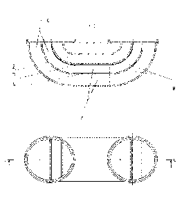
  • G01F 1/66 (2022.01)
(72) Inventors :
  • MIKAN, JAROSLAV (Czechia)
(73) Owners :
  • OIL&GAS METERING EQUIPMENT S.R.O.
(71) Applicants :
  • OIL&GAS METERING EQUIPMENT S.R.O. (Czechia)
(74) Agent: GOWLING WLG (CANADA) LLP
(74) Associate agent:
(45) Issued: 2024-02-20
(86) PCT Filing Date: 2021-06-10
(87) Open to Public Inspection: 2021-11-18
Examination requested: 2021-12-15
Availability of licence: N/A
Dedicated to the Public: N/A
(25) Language of filing: English

Patent Cooperation Treaty (PCT): Yes
(86) PCT Filing Number: PCT/IB2021/055096
(87) International Publication Number: WO 2021229554
(85) National Entry: 2021-12-15

(30) Application Priority Data:
Application No. Country/Territory Date
PV 2020-381 (Czechia) 2020-06-29

Abstracts

English Abstract

The present invention relates to the gas flow conditioner in the flow bend (1), in particular in the ultrasonic flow meter where at least one longitudinal dividing plate (2) is provided in the inner space (5) of the flow bend. The flow bend (1) is preferably provided with the inlet curved section (6), the middle straight section (7) and the outlet curved section (8), wherein the axes of the inlet curved section (6) and the outlet curved section (8) are in a parallel direction and connected to the pipe opening of size DN.


French Abstract

La présente invention concerne un conditionneur de flux de gaz dans une courbe de flux (1), en particulier dans un débitmètre à ultrasons dans lequel au moins une plaque de séparation longitudinale (2) est disposée, dans l'espace intérieur (5) de la courbe de flux. La courbe de flux (1) comprend de préférence la section coubée d'entrée (6), la section droite intermédiaire (7) et la section courbée de sortie (8), les axes de la section courbée d'entrée (6) et de la section courbée de sortie (8) se trouvent dans un sens parallèle et sont reliés à l'ouverture de tuyau de taille DN.

Claims

Note: Claims are shown in the official language in which they were submitted.

Claims
[Claim 1] A gas flow conditioner in a flow bend (1), in an ultrasonic flow
meter, wherein at
least one longitudinal dividing plate (2) is provided in an inner space (5) of
the
flow bend; and
wherein the flow bend (1) is provided with an inlet curved section (6), a
middle
straight section (7) and an outlet curved section (8), wherein axes of the
inlet
curved section (6) and the outlet curved section (8) are in a parallel
direction and
connected to the pipe opening of size DN.
[Claim 2] The gas flow conditioner according to claim 1, wherein at least one
longitudinal
plate (2) is symmetrically positioned in the flow bend (1) with respect to an
axis
of the flow bend (1).
[Claim 3] The gas flow conditioner according to claim 1, wherein at least one
longitudinal
plate (2) is asymmetrically positioned in the flow bend (1) with respect to an
axis
of the flow bend (1).
[Claim 4] The gas flow conditioner according to any one of claims 1 to 3,
wherein the axis
of the middle straight section (7) is in a horizontal direction.
[Claim 5] The gas flow conditioner according to any one of claims 1 to 3,
wherein the axis
of the middle straight section (7) is in a vertical direction.
[Claim 6] The gas flow conditioner according to any one of claims 1 to 5,
wherein the
Reynolds number for DN-sized pipe is higher than 2,320.
6
Date Recue/Date Received 2023-05-30

Description

Note: Descriptions are shown in the official language in which they were submitted.


CA 03143624 2021-12-15
WO 2021/229554 PCT/IB2021/055096
Title of Invention : Gas flow conditioner in the flow bend,
especially for ultrasonic gas meter
Technical Field
[0001] The technical solution refers to a gas flow conditioner in a flow bend,
i.e. a segment, arc or
elbow, etc., where the direction of gas flow bends, upstream or downstream of
a measuring part.
This solution is used for gas measurement with ultrasonic gas meters,
especially in natural gas
distribution.
Background Art
[0002] All gas flow conditioners are currently being placed in a straight pipe
upstream
of the ultrasonic gas meter. Measurement with ultrasonic sensors is carried
out at
some distance from this conditioner after the flow has stabilised. Any bending
will
cause flow disturbances that negatively affect the measurement accuracy of the
ultrasonic gas meters.
[0003] There is no conditioner for the ultrasonic gas meter that could be
placed in the
bend of the gas flow.
[0004] The main disadvantages of the existing conditioners for ultrasonic gas
meters
include the fact that they can only be used in straight pipelines, and the
measuring section with ultrasonic sensors must be located at some distance
downstream of the conditioner. The existing conditioners cause a significant
pressure loss and become clogged with various particles of dirt, especially in
small openings thereof. For the existing conditioners, production thereof is
expensive and usually one-off. The existing conditioners are usually not being
placed directly in the meter body but at a certain distance upstream of the
meter,
up to 10 DN. Any bend between the flow conditioner and the measuring section
will cause large flow disturbances, i.e. the formation of swirls, which have a
negative impact on the accuracy and range of measurement.
[0005] There are several flow conditioner designs for ultrasonic gas meters,
the most
common of which is a perforated-plate conditioner placed at some distance
upstream of the ultrasonic sensor measuring section. This conditioner develops
a
1

CA 03143624 2021-12-15
WO 2021/229554 PCT/IB2021/055096
so-called "laminar velocity profile". This laminar velocity profile is
suitable for
measurements on large pipe dimensions, at high pressure and flow rates. An
ultrasonic gas meter designed to measure on the laminar profile must have a
large number of ultrasonic sensors. Such an ultrasonic gas meter design is
expensive and only suitable for large pipe diameters.
[0006] Various other types of flow conditioners are known from technical
practice. In
particular, these include the Zanker's flow conditioner, Zanker's plate flow
conditioner, Sprekle's flow conditioner, Gallagher's flow conditioner, K-Lab
NOVA
flow conditioner, NEL (Spearman's) flow conditioner, etc. The above flow
conditioners have a significant pressure loss, must be placed in a straight
pipe
upstream of the ultrasonic gas meter and are complex and expensive to
manufacture.
[0007] The principle of the ultrasonic gas meter is based on measuring the
velocity of
ultrasonic waves, i.e. signals, in the direction and the opposite direction of
the
gas flow. The ultrasonic sensors are located obliquely to the pipe axis, and
the
flow time between the transmitter and the receiver of the signal is measured.
The
ultrasonic signals are accelerated or decelerated by the flowing gas. From the
different times, the mean gas flow velocity or flow rate or flow quantity is
determined.
Summary of Invention
[0008] The above deficiencies are eliminated mainly by a gas flow conditioner
in a
flow bend, such as a segment, arc, or elbow, particularly in an ultrasonic
flow
meter, according to the present invention. The summary thereof is that at
least
one longitudinal dividing plate is provided in the inner space of the flow
bend.
[0009] The flow bend is preferably provided with an inlet curved section, a
middle
straight section and an outlet curved section, wherein the axes of the inlet
curved
section and the outlet curved section are in a parallel direction and
connected to
the pipe opening of nominal diameter DN.
[0010] At least one longitudinal plate is placed in the flow bend
symmetrically with
respect to the flow bend axis or asymmetrically with respect to the flow bend
axis.
The axis of the middle straight section may be positioned in the horizontal
2

CA 03143624 2021-12-15
WO 2021/229554 PCT/IB2021/055096
direction or the vertical direction. The Reynolds number for DN-sized piping
is
higher than 2,320.
[0011] The summary of the invention is to propose a new solution for a flow
conditioner, which consists of curved plates in the number of 1 to n pieces,
which
creates a turbulent flow, eliminating flow disturbances, such as swirls, and
reducing pressure loss.
[0012] In turbulent flow, the velocity profile is very flat and the gas flows
at almost the
same velocity over most of the flow cross-section. The kind of flow produced
is
determined by the so-called Reynolds number Re. This is a dimensionless
number, and the theoretical limit is set by the value 2,320. Below this value,
we
speak of laminar flow, and above this value, we speak of turbulent flow. The
invention solution aims for the value of ReD, i.e. the Reynolds number for the
DN-sized pipe, to be significantly higher than the theoretical limit.
[0013] The plates' number, shape, and positioning are carried out based on
measurement by numerical simulation method and Particle Image Velocimetry ¨
Ply. This method will illustrate where the plates are appropriate to be placed
and
what the ideal thickness of the plates is. The number of plates can be varied
depending on the operating conditions and customer specifications.
[0014] The advantages of the solution, according to the invention, consist
primarily in
that it eliminates the effect of small and large disturbances arising in the
pipeline
upstream of the gas meter. The solution is suitable to be used in a section of
the
pipeline where the direction of gas flow changes. The measuring section with
ultrasonic sensors may be placed almost just behind this conditioner. The
designed conditioner reduces the pressure loss. A significant advantage is
that
the conditioner is not clogged with various impurities because the openings
used
are sufficiently large.
[0015] The conditioner can be easily and inexpensively manufactured, even in
large-
scale production. The conditioner is suitable to be placed inside a compact
ultrasonic gas meter, and, thus, the required construction length, i.e. the
dimension between the flanges, can be achieved. The solution eliminates the
flow disturbances arising in the bend, thus ensuring high accuracy and a large
3

CA 03143624 2021-12-15
WO 2021/229554 PCT/IB2021/055096
measuring range with ultrasonic sensors. The conditioner needs no maintenance
as it is designed in materials such as aluminium or plastic, which are not
subject
to wear and tear and corrosion. The shape of the conditioner does not allow
dirt
to accumulate. The lifetime of the conditioner is the same as that of the
ultrasonic
gas meter; therefore, there is no increase in the cost of ownership of the
meter.
The conditioner can be made of a single material and can be removed from the
gas meter, which considerably simplifies separation and subsequent recycling
at
the end of the service life thereof.
Brief Description of Drawings
[0016] The flow conditioner, according to the present invention, is described
in more
detail in a particular example embodiment referring to the accompanying
drawings, wherein Fig. 1 shows an exemplary flow conditioner, in particular
for
natural gas, in axonometric view. Fig. 2 shows a segment with the conditioner
in
cross-section and plan view. Fig. 3 shows a longer embodiment of the flow
conditioner, particularly for natural gas, in axonometric view. Specific use
of
conditioners with curved plates is shown in Fig. 4, depicting longitudinal
sections
of ultrasonic gas meters.
Examples of the Invention Embodiments
[0017] The exemplary flow conditioner in the bend segment, shown in Figures 1
and
2, comprises bend segment 1 with three longitudinal plates 2, 3 and 4. The
segment is shaped to allow a change in the flow direction of up to 1800, i.e.
the
flow direction upstream of the segment is opposite to the flow direction
downstream of the segment. The segment is fitted onto two parallel pipes, i.e.
two parallel circular openings. The distance between the pipes can be chosen
arbitrarily; the distance between the pipes does not affect the function of
the flow
conditioner ¨ Fig. 3.
[0018] The plates 2, 3, 4 are shaped according to the shape of bend 1 of the
segment and consist of three sections ¨ the inlet curved section 6, the middle
straight section 7, and the outlet curved section 8. The radius of curvature
is
chosen to create the desired velocity profile.
4

CA 03143624 2021-12-15
WO 2021/229554 PCT/IB2021/055096
[0019] The position of plates 2, 3, 4 can be proportional, or the plates 2, 3,
4 are
placed more densely to one side to achieve the optimum velocity profile. The
conditioner can be placed in both horizontal and vertical directions. The
conditioner can be used for different DN sizes of the pipe. The number of
plates 2,
3, 4 will depend on the DN size. For the smallest size, there will be 1 or 2
plates;
with a larger size, the number of plates will increase, e.g. 3 to n.
[0020] The conditioner can be made of various materials, e.g. plastic, metal,
etc.
Possible manufacturing technologies include 3D printing of plastics and
metals,
metal welding, plastic injection moulding, etc. The material and technology
used
will always depend on the requirements of the specific market. The position of
the
plates is determined by the required measuring range of the gas meter.
[0021] This flow conditioner will be placed in the compact ultrasonic gas
meter, see
application CZ PV 2019 ¨ 161.
Industrial Applicability
[0022] The flow conditioner, according to the present invention, will find the
application thereof primarily in gas measurement, in ultrasonic flow meters,
in
particular in natural gas distribution in households, municipal and industrial
buildings and the like.

Representative Drawing
A single figure which represents the drawing illustrating the invention.
Administrative Status

2024-08-01:As part of the Next Generation Patents (NGP) transition, the Canadian Patents Database (CPD) now contains a more detailed Event History, which replicates the Event Log of our new back-office solution.

Please note that "Inactive:" events refers to events no longer in use in our new back-office solution.

For a clearer understanding of the status of the application/patent presented on this page, the site Disclaimer , as well as the definitions for Patent , Event History , Maintenance Fee  and Payment History  should be consulted.

Event History

Description Date
Inactive: Office letter 2024-03-28
Inactive: Grant downloaded 2024-02-23
Letter Sent 2024-02-20
Grant by Issuance 2024-02-20
Inactive: Cover page published 2024-02-19
Pre-grant 2024-01-04
Inactive: Final fee received 2024-01-04
Letter Sent 2023-09-11
Notice of Allowance is Issued 2023-09-11
Inactive: Approved for allowance (AFA) 2023-08-21
Inactive: Q2 passed 2023-08-21
Amendment Received - Response to Examiner's Requisition 2023-05-30
Amendment Received - Voluntary Amendment 2023-05-30
Examiner's Report 2023-01-30
Inactive: Report - No QC 2023-01-26
Inactive: Cover page published 2022-01-28
Priority Claim Requirements Determined Compliant 2022-01-12
Letter sent 2022-01-12
Letter Sent 2022-01-12
Inactive: First IPC assigned 2022-01-11
Request for Priority Received 2022-01-11
Inactive: IPC assigned 2022-01-11
Application Received - PCT 2022-01-11
National Entry Requirements Determined Compliant 2021-12-15
Request for Examination Requirements Determined Compliant 2021-12-15
All Requirements for Examination Determined Compliant 2021-12-15
Small Entity Declaration Determined Compliant 2021-12-15
Application Published (Open to Public Inspection) 2021-11-18

Abandonment History

There is no abandonment history.

Maintenance Fee

The last payment was received on 2023-05-19

Note : If the full payment has not been received on or before the date indicated, a further fee may be required which may be one of the following

  • the reinstatement fee;
  • the late payment fee; or
  • additional fee to reverse deemed expiry.

Please refer to the CIPO Patent Fees web page to see all current fee amounts.

Fee History

Fee Type Anniversary Year Due Date Paid Date
Request for examination - small 2025-06-10 2021-12-15
Basic national fee - small 2021-12-15 2021-12-15
MF (application, 2nd anniv.) - small 02 2023-06-12 2023-05-19
Final fee - small 2024-01-04
MF (patent, 3rd anniv.) - small 2024-06-10 2024-03-15
Owners on Record

Note: Records showing the ownership history in alphabetical order.

Current Owners on Record
OIL&GAS METERING EQUIPMENT S.R.O.
Past Owners on Record
JAROSLAV MIKAN
Past Owners that do not appear in the "Owners on Record" listing will appear in other documentation within the application.
Documents

To view selected files, please enter reCAPTCHA code :


To view images, click a link in the Document Description column. To download the documents, select one or more checkboxes in the first column and then click the "Download Selected in PDF format (Zip Archive)" or the "Download Selected as Single PDF" button.

List of published and non-published patent-specific documents on the CPD .

If you have any difficulty accessing content, you can call the Client Service Centre at 1-866-997-1936 or send them an e-mail at CIPO Client Service Centre.


Document
Description 
Date
(yyyy-mm-dd) 
Number of pages   Size of Image (KB) 
Representative drawing 2024-01-29 1 18
Cover Page 2024-01-29 1 52
Claims 2023-05-30 1 41
Description 2021-12-15 5 220
Drawings 2021-12-15 3 119
Claims 2021-12-15 1 34
Abstract 2021-12-15 2 71
Representative drawing 2021-12-15 1 24
Cover Page 2022-01-28 1 50
Final fee 2024-01-04 4 100
Electronic Grant Certificate 2024-02-20 1 2,527
Maintenance fee payment 2024-03-15 1 26
Courtesy - Office Letter 2024-03-28 2 189
Courtesy - Letter Acknowledging PCT National Phase Entry 2022-01-12 1 587
Courtesy - Acknowledgement of Request for Examination 2022-01-12 1 423
Commissioner's Notice - Application Found Allowable 2023-09-11 1 579
Amendment / response to report 2023-05-30 9 250
Patent cooperation treaty (PCT) 2021-12-15 2 87
International search report 2021-12-15 3 86
National entry request 2021-12-15 8 230
Examiner requisition 2023-01-30 3 176