Note: Descriptions are shown in the official language in which they were submitted.
AUTOMATED CATHETER AND CHEST TUBE DEVICES AND RELATED
SYSTEMS
CROSS-REFERENCE TO RELATED APPLICATIONS
The present application claims priority to U.S. Provisional Patent
Application Serial No. 62/861,169, filed June 13, 2019, and U.S. Provisional
Patent Application Serial No. 62/861,165, filed June 13, 2019.
TECHNICAL FIELD
The subject matter herein generally relates to the field of catheters,
chest tubes, and related devices. The subject matter herein more particularly
relates to, automated catheter devices and related systems, including urinary
catheters and chest tubes.
BACKGROUND
Modern medical catheters, particularly Foley catheters, are used to
collect urine in patients while admitted to hospitals and medical facilities.
However, the amount of urine collected by the catheter is not automatically
calculated, and the data is not available electronically via a computer.
Instead,
urine output must be manually measured or observed, and the data manually
charted or recorded when time permits. This can be detrimental to the patient
because if a nurse, Nursing Assistant, technician or other medical
professional
forgets to chart the amount of periodic output a provider will assume there
was
no urine output. There are numerous potentials for errors including, but not
limited to spilled urine and incorrect or imprecise measurements. This is
crucial in providing proper medical care. For example, if a patient is
admitted
with a diagnosis such as diabetes insipidus, proper recording and utilization
of urine output can be a life or death proposition.
In a similar vein, chest tubes are used to collect air, fluid, pleural
effusion, blood, chyle, or pus from the intrathoracic space of a patient while
admitted to hospitals and medical facilities, and/or otherwise under medical
care. However, the amount of air, fluid, pleural effusion, blood, chyle, or
pus
collected by the chest tube is not automatically calculated, and the data is
not
-1-
Date Recue/Date Received 2023-05-30
available electronically via a computer. Instead, the amount of air or fluid
output must be manually measured or observed, and the data manually
charted or recorded when time permits. Similarly to the urine catheter issues
described above, if the nurse, or other professional, fails to chart the
periodic
air, fluid, pleural effusion, blood, chyle, or pus collected from the patient,
a
provider will assume there was no output. These types of charting are critical
for receiving the proper treatment and, just like with the catheter, the
potential
consequence for error could be deadly. For example, if a patient is admitted
with a particular condition, proper recording and utilization of air, fluid,
pleural
effusion, blood, chyle, or pus output can be a life or death proposition.
Thus, what is needed is an automated system delivering results in real-
time or a device that collects, measures and/or records urine output and/or
air, flud, pleural effusion, blood, chyle, and/or puss output with minimal or
no
effort by medical personnel. Such need is addressed by the devices and
system described herein.
SUMMARY
In accordance with this disclosure, smart catheter and smart chest tube
devices and systems are provided. In one aspect, a smart catheter is
provided, the smart catheter comprising: a flexible tube with an opening at a
first end; a drainage port at an opposing second end; an inflatable balloon at
the first end, and proximate to the opening; a balloon port at the second end
and proximate to the drainage port; and a measuring device, comprising one
or more sensors, integrated into or attached to the flexible tube and
configured
to measure an amount of fluid flowing therethrough. In some embodiments,
the smart catheter is configured to drain urine from a bladder of a patient,
and
the measuring device is a flow meter sensor. In some embodiments, the
drainage port is configured to connect or otherwise attach to one or more
collection reservoirs; and the smart catheter is configured to deposit urine
in
the one or more collection reservoirs.
In another aspect, there this provided a smart catheter which comprises
an enclosure and a flexible tube with an opening at a first end of the
flexible
tube. The flexible tube has a drainage port at a second end where the second
-2-
Date Recue/Date Received 2023-05-30
end is opposite the first end. There is an inflatable balloon provided at the
first
end, proximate to the opening, and a balloon port is provided at the second
end. One or more collection reservoirs are provided and removably contained
within the enclosure and configured to receive a flow of a fluid therein from
the
flexible tube. A flow meter is contained within the enclosure and attached
between the drainage port and the one or more collection reservoirs, wherein
the flow meter is configured to measure a flow rate of the fluid flowing
through
the flow meter and the drainage port is fluidically connected to the one or
more
collection reservoirs within the enclosure to, when in use, collect fluid from
a
user.
In some further embodiments, the flow meter sensor is
configured to measure the amount of urine deposited into the one or more
collection reservoirs. In some embodiments, the flexible tube comprises two
separated channels or lumens running along a length of the flexible tube,
wherein a first lumen, open at both ends, connects the opening at the first
end
to the drainage port at the second end, wherein the second lumen connects
the inflatable balloon to the balloon port. In some embodiments, the measuring
device is integrated into and/or along a length of the flexible tube at any
suitable location. In some embodiments, the measuring device comprises a
transmitter that is configured to transmit data to one or more processors in
communication with the measuring device.
In some further embodiments, the transmitted data comprises urine
flow data; the one or more processors is configured to store and monitor the
urine flow data; the one or more processors is configured to monitor an
amount of urine deposited into one or more collection reservoirs of the smart
catheter; and the one or more processors is configured to transmit a warning
signal or trigger an alarm when at least one of the one or more collection
reservoirs of the smart catheter reaches one or more thresholds. In some
embodiments, the one or more processors is configured to transmit a warning
signal or trigger an alarm when there is a malfunction of the smart catheter.
In
some embodiments, components of the smart catheter are housed in an
enclosure comprising a display screen; and the display screen is configured
to display fill levels of one or more collection reservoirs of the smart
catheter.
-3-
Date Recue/Date Received 2023-05-30
In some embodiments, the enclosure further comprises a transparent
or non-transparent door; and wherein each of the one or more collection
reservoirs is either transparent or non-transparent. In some embodiments, one
or more of the collection reservoirs comprises a total dissolved solids meter
and/or a color sensor configured to detect and measure a color or shade of a
fluid. In some embodiments, one or more of the collection reservoirs
comprises a quick connect port to connect the one or more collection
reservoirs to the smart catheter. In some embodiments, when a first collection
reservoir is removed from the smart catheter, the smart catheter is configured
to automatically select a second collection reservoir and start draining urine
into the second collection reservoir. In some embodiments, each of the one or
more collection reservoirs comprises an electrical connection configured to
provide power to various components in a respective collection reservoir and
to connect the one or more processors to the various components in the
respective collection reservoir.
In another aspect, a smart catheter system is provided, the smart
catheter system comprising a smart catheter of any of the above
embodiments; and an external device, wherein the external device comprises
a tablet, computer, phone, smart watch, audio device or display device. In
some embodiments, wherein the system further comprises: a power source,
one or more processors, memory, a receiver or transmitter, a display, an
accelerometer, a speaker and/or a tactile signal device, wherein the smart
catheter, power source, one or more processors, memory, receiver or
transmitter, display, accelerometer, speaker or tactile signal device are
interconnected with one another. In some embodiments, the display is
configured to display information about the patient and/or the smart catheter.
In some embodiments, the display is configured to display identification
information about the patient as well as information regarding the patient's
urine; and wherein the display is configured to display information about a
capacity of each of the one or more collection reservoirs or a warning or
error
message. In some embodiments, the smart catheter system comprises a
computer program product comprising computer executable instructions
embodied in a computer readable medium for performing steps comprising
-4-
Date Recue/Date Received 2023-05-30
receiving an electrical signal from a measuring apparatus, processing the
electrical signal to calculate data pertaining to a measured volume, and
relaying the data to the electronic display, speaker, tactile signal device or
external device. In some embodiments, the smart catheter system are
configured to measure and calculate a volume of urine or other body fluid
produced by a patient every 30 minutes or Q one hour, wherein the calculated
volume is processed by a computer and entered into an electronic charting
system.
In some embodiments, the smart catheter system is configured to
measure and calculate the volume of urine or other body fluid produced by a
patient and activate an alarm if the volume of urine and/or other body fluid
is
above and/or below a predetermined threshold. In some embodiments, the
smart catheter or smart catheter system of any of the above embodiments,
where the smart catheter or smart catheter system is configured as a chest
tube.
In another aspect a smart chest tube is provided, the smart chest tube
comprising: a flexible tube with an opening at a first end; a drainage port at
the opposing second end; and a measuring device, comprising one or more
sensors, integrated into or attached to the flexible tube and configured to
measure an amount of fluid flowing the rethrough.
In yet another aspect, there is provided a smart chest tube which
comprises an enclosure and a flexible tube with an opening at a first end of
the flexible tube and a drainage port at a second end of the flexible tube
where
the second end is opposite the first end. One or more collection reservoirs
are provided and removably contained within the enclosure which are
configured to receive a flow of a bodily fluid therein from the flexible tube.
There is further provided a flow meter contained within the enclosure and
attached between the drainage port and the one or more collection reservoirs,
wherein the flow meter is configured to measure a flow rate of the bodily
fluid
flowing through the flow meter. Additionally, the drainage port is fluidically
connected to the one or more collection reservoirs within the enclosure to,
when in use, collect the bodily fluid from a user.
-5-
Date Recue/Date Received 2023-05-30
In some embodiments, the chest tube is configured to drain air, fluid, pleural
effusion, blood, chyle, or pus from a chest cavity of a patient, and wherein
the
measuring device is a fluid flow meter sensor. In some embodiments, the
drainage port is configured to connect or otherwise attach to one or more
collection reservoirs; and the smart chest tube is configured to deposit air,
fluid, pleural effusion, blood, chyle, or pus in the one or more collection
reservoirs. In some embodiments, the flow meter sensor is configured to
measure the amount of air, fluid, pleural effusion, blood, chyle, or pus
deposited into the one or more collection reservoirs.
In some further embodiments, the measuring device is integrated into
and/or along a length of the flexible tube at any suitable location. In some
embodiments, the measuring device comprises a transmitter that is configured
to transmit data to one or more processors in communication with the
measuring device. In some embodiments, the transmitted data comprises flow
data regarding air, fluid, pleural effusion, blood, chyle, or pus flowing
through
the flexible tube and measured by the measuring device; the one or more
processors is configured to store and monitor the flow data; the one or more
processors is configured to monitor an amount of air, fluid, pleural effusion,
blood, chyle, or pus deposited into one or more collection reservoirs of the
smart chest tube; the one or more processors is configured to transmit a
warning signal or trigger an alarm when at least one of the one or more
collection reservoirs of the smart chest tube reaches one or more thresholds.
In some further embodiments, the one or more processors is
configured to transmit a warning signal or trigger an alarm when there is a
malfunction of the smart chest tube. In some embodiments, components of
the smart chest tube are housed in an enclosure comprising a display screen;
and the display screen is configured to display fill levels of one or more
collection reservoirs of the smart chest tube. In some embodiments, the chest
tube system is configured to measure and calculate a volume of air or a body
fluid produced by a patient and activate an alarm if the volume of air or a
body
fluid is above or below one or more predetermined thresholds.
In some further embodiments, one or more of the collection reservoirs
comprises a total dissolved solids meter and/or a color sensor configured to
-6-
Date Recue/Date Received 2023-05-30
detect and measure a color or shade of a fluid. In some embodiments, one or
more of the collection reservoirs comprises a quick connect port to connect
the one or more collection reservoirs to the smart chest tube. In some
embodiments, when a first collection reservoir is removed from the smart
chest tube, the smart chest tube is configured to automatically select a
second
collection reservoir and start draining body fluid into the second collection
reservoir. In some embodiments, each of the one or more collection reservoirs
comprises an electrical connection configured to provide power to various
components in a respective collection reservoir and to connect the one or
more processors to the various components in the respective collection
reservoir.
In some embodiments, a smart chest tube system is provided, the
system comprising a smart chest tube as disclosed herein; and an external
device, wherein the external device comprises a tablet, computer, phone,
smart watch, audio device or display device. In some embodiments, the
system further comprises: a power source, one or more processors, memory,
a receiver or transmitter, a display, an accelerometer, a speaker and/or a
tactile signal device, wherein the power source, one or more processors,
memory, receiver or transmitter, display, accelerometer, speaker or tactile
signal device are interconnected with one another. In some embodiments,
the display is configured to display information about the patient and/or the
smart catheter.
In some embodiments, the display is configured to display identification
information about the patient as well as information regarding the patient's
urine; and wherein the display is configured to display information about a
capacity of each of the one or more collection reservoirs or a warning or
error
message. In some embodiments, the smart chest tube system further
comprises a computer program product comprising computer executable
instructions embodied in a computer readable medium for performing steps
comprising receiving an electrical signal from a measuring apparatus,
processing the electrical signal to calculate data pertaining to a measured
volume, and relaying the data to the electronic display, speaker, tactile
signal
device or external device. In some embodiments, the smart chest tube system
-7-
Date Recue/Date Received 2023-05-30
is configured to measure and calculate a volume of air or a body fluid
produced
by a patient every 30 minutes or Q one hour, wherein the calculated volume
is processed by a computer and entered into an electronic charting system. In
some further embodiments, the chest tube system is configured to measure
and calculate the volume of air or a body fluid produced by a patient and
activate an alarm if the volume of air or a body fluid is above and/or below a
predetermined threshold.
Although some of the aspects of the subject matter disclosed herein
have been stated hereinabove, and which are achieved in whole or in part by
the presently disclosed subject matter, other aspects will become evident as
the description proceeds when taken in connection with the accompanying
drawings as best described hereinbelow.
BRIEF DESCRIPTION OF THE DRAWINGS
The features and advantages of the present subject matter will be more
readily understood from the following detailed description which should be
read in conjunction with the accompanying drawings that are given merely by
way of explanatory and non-limiting example, and in which:
FIG. 1A is a perspective view of a smart catheter device according to
an embodiment of the presently disclosed subject matter;
FIG. 1B is a perspective view of a smart catheter device according to
an embodiment of the presently disclosed subject matter with a display
glowing in the dark;
FIG. 2A depicts a front view of a smart catheter device according to an
embodiment of the presently disclosed subject matter;
FIG. 2B and FIG. 2C depict a side view of a smart catheter device and
illustrates the details of the flexible tube according to an embodiment of the
presently disclosed subject matter;
FIG. 3A and FIG. 3B are perspective views of a smart catheter device
according to an embodiment of the presently disclosed subject matter with a
door of the smart catheter ajar, exposing the internal components of the smart
catheter;
-8-
Date Recue/Date Received 2023-05-30
FIG. 4A and FIG. 4B are close-up views of vials or collection reservoirs
of a smart catheter device according to an embodiment of the presently
disclosed subject matter;
FIG. 5 is an exploded view of a vial or collection reservoir of a smart
catheter device according to an embodiment of the presently disclosed subject
matter;
FIG. 6A is a perspective bottom view and a side view of a smart
catheter device according to an embodiment of the presently disclosed subject
matter;
FIG. 6B depicts perspective rear views of a smart catheter device
according to an embodiment of the presently disclosed subject matter;
FIG. 7 is a close-up perspective top view of a smart catheter device
according to an embodiment of the presently disclosed subject matter; and
FIG. 8 is a close-up perspective to view of a smart chest tube device
and illustrates the details of the flexible tube according to an embodiment of
the presently disclosed subject matter.
DETAILED DESCRIPTION
The present subject matter provides automated or smart catheter
systems and devices and automated or smart chest tube systems and
devices. In one aspect, the present subject matter provides smart catheter
systems and devices for draining, storing, and measuring urine from a patient
and warning or alerting healthcare officials once the urine levels get to a
certain level or the device malfunctions. In similar aspect, the present
subject
matter provides smart chest tube systems and device for draining, storing, and
measuring bodily fluids from a patient and warning or alerting healthcare
officials once the bodily fluid levels reach a certain threshold. While the
following terms are believed to be well understood by one having ordinary
skill
in the art, the following definitions are set forth to facilitate explanation
of the
presently disclosed subject matter.
Unless defined otherwise, all technical and scientific terms used herein
have the same meaning as commonly understood to one having ordinary skill
in the art to which the presently disclosed subject matter belongs. Although,
-9-
Date Recue/Date Received 2023-05-30
any methods, devices, and materials similar or equivalent to those described
herein can be used in the practice or testing of the presently disclosed
subject
matter, representative methods, devices, and materials are now described.
Following long-standing patent law convention, the terms "a", "an", and
"the" refer to "one or more" when used in this application, including the
claims.
Thus, for example, reference to "a vial" can include a plurality of such
vials,
and so forth.
Unless otherwise indicated, all numbers expressing quantities of
length, diameter, width, and so forth used in the specification and claims are
to be understood as being modified in all instances by the terms "about" or
"approximately". Accordingly, unless indicated to the contrary, the numerical
parameters set forth in this specification and attached claims are
approximations that can vary depending upon the desired properties sought
to be obtained by the presently disclosed subject matter.
As used herein, the terms "about" and "approximately," when referring
to a value or to a length, width, diameter, temperature, time, volume,
concentration, percentage, etc., is meant to encompass variations of in some
embodiments 20%, in some embodiments 10%, in some embodiments
5%, in some embodiments 1%, in some embodiments 0.5%, and in some
embodiments 0.1% from the specified amount, as such variations are
appropriate for the disclosed apparatuses and devices.
The term "comprising", which is synonymous with "including"
"containing" or "characterized by" is inclusive or open-ended and does not
exclude additional, unrecited elements or method steps. "Comprising" is a
term of art used in claim language which means that the named elements are
essential, but other elements can be added and still form a construct within
the scope of the claim.
As used herein, the phrase "consisting or excludes any element, step,
or ingredient not specified in the claim. When the phrase "consists of"
appears
in a clause of the body of a claim, rather than immediately following the
preamble, it limits only the element set forth in that clause; other elements
are
not excluded from the claim as a whole.
-10-
Date Recue/Date Received 2023-05-30
As used herein, the phrase "consisting essentially of" limits the scope
of a claim to the specified materials or steps, plus those that do not
materially
affect the basic and novel characteristic(s) of the claimed subject matter.
With respect to the terms "comprising", "consisting of", and "consisting
essentially of", where one of these three terms is used herein, the presently
disclosed and claimed subject matter can include the use of either of the
other
two terms.
As used herein, the term "and/or" when used in the context of a listing
of entities, refers to the entities being present singly or in combination.
Thus,
for example, the phrase "A, B, C, and/or D" includes A, B, C, and D
individually, but also includes any and all combinations and sub-combinations
of A, B, C, and D.
Smart Catheter Devices and Systems
Urinary catheters are used to collect urine in patients while admitted to
hospitals and medical facilities, as well as at home and for chronic use. The
urine output is manually collected and measured by nurses and other medical
professionals. Unfortunately, there is no automated system for performing this
important task. Instead, urine output must be manually measured or observed,
and the data manually charted or recorded, usually hours after. This is a
crucial step in providing proper medical care, but due to the manual nature of
this task it can easily be overlooked or delayed. An automated or smart system
or device that collects, measures and/or records urine output with minimal or
no effort by medical personnel would improve efficiency, accuracy, best
practice, health care effectiveness and successful patient outcomes. The
disclosed devices and systems fill this unmet need. Particularly, the
disclosed
devices and systems automatically collect, measure, calculate and record
urine output and other related data. In some embodiments, such catheters
and catheter systems can be referred to as a precise catheter, smart catheter,
electronic catheter, and the like, or precise Foley, smart Foley, electronic
Foley, and the like.
-11-
Date Recue/Date Received 2023-05-30
Referring to FIG. 1A, which depicts a perspective view of one
embodiment of a possible smart catheter 100 of the present disclosure
attached to the side of a hospital bed. In some embodiments, the smart
catheter 100 can have an enclosure or housing that houses a subset of its
components. The housing or enclosure can have a door 102 that swings open
revealing any components within. In some embodiments, the smart catheter
100 can also comprise a display 104, a flexible tube 106 (i.e., the actual
urinary catheter component), and a lighting element 108. Referring to FIG. 1B,
in some embodiments, the lighting element 108 can light up the room it is in
like a night light, allowing nurses, doctors, and other health professionals
to
view the display without disturbing the patient by cutting on the lights in
the
room to see the contents of the catheter collection reservoir(s). The
characteristics of the various components are described further hereinbelow.
Referring to FIG. 2A, which illustrates a front exterior view of a possible
smart catheter 100 of the present disclosure. In some embodiments, the door
102 includes a pattern 110, grooves, or other indicia indicating the direction
in
which the door 102 opens. This will allow medical professionals to easily
determine which way to open the door to increase efficiencies when trying to
inspect or exchange components inside the housing of the smart catheter 100.
As shown in FIG. 2B, in some embodiments, the smart catheter 100 of
the present disclosure can comprise a clamp and/or bracket 112 on the back
of the housing, which can be used to temporarily or permanently fasten or
attach the smart catheter 100 to a surface, such as, for example, the side of
a
hospital bed, a table, or other suitable location. In some embodiments, the
smart catheter 100 can be configured such that the flexible tube 106 used to
drain the urine can ingress into the smart catheter 100 through the top of the
housing. In some embodiments, the flexible tube 106 can ingress into the back
of the smart catheter 100 or any other suitable location.
In some embodiments, the smart catheter 100 of the present disclosure
can comprise a urinary catheter used to drain urine from the bladder of a
patient. In some embodiments, the urinary catheter can comprise, for example
and without limitation, a Foley catheter, comprising a flexible tube 106 which
a clinician passes through the urethra of a patient and into the patient's
-12-
Date Recue/Date Received 2023-05-30
bladder to drain urine. In some embodiments, the flexible tube 106 comprises
a bladder opening 106-1 at one end and a urine drainage port at an opposing
second end (not visible in this view because it is located inside the
housing).
The bladder opening 106-1 end can be passed through the patient's urethra
until the bladder opening 106-1 reaches the patients' bladder. The urine
drainage port can be configured to connect or otherwise attach to a collection
reservoir, described further herein.
Referring to FIG. 2C, in some embodiments, the flexible tube 106 can
also include an inflatable balloon 106-2 at or near the end where the bladder
opening 106-1 resides, and a balloon port at the opposing end near where the
drainage port resides (i.e., connects to the smart catheter housing). In some
aspects, the flexible tube 106 has two separate channels or lumens running
down its length. One lumen, open at both ends, connects the bladder opening
106-1 to the urine drainage port and is configured to drain urine from the
bladder, through the lumen, out the drainage port and into a collection
reservoir, such as, for example and without limitation, a collection bag. The
other lumen connects the balloon port 106-2 and the balloon. The balloon 106-
2 is inflated with sterile water when it lies inside the bladder to stop the
catheter or flexible tube 106 from slipping out.
In some embodiments, the flexible tube 106 can be made of silicone or
other suitable material and/or coated natural latex. Coatings can including
polytetrafluoroethylene, hydrogel, or a silicon elastomer. In some instances,
the different properties of these surface coatings can determine the suitable
duration of use, e.g. whether the catheter is suitable for 28-day or 3-month
indwelling duration. Additionally, catheters are also changed if soiled,
leaking,
or if an infection is present.
In some embodiments, the smart catheter 100 can comprise one or
more processors (not shown), non-transitory computer readable media, and
executable instructions used to operate the various automated functions of
the device. In some embodiments, the one or more processors can be
configured to operate the display 104, perform various measurements based
on sensors described herein, and perform various other functions as
described herein.
-13-
Date Recue/Date Received 2023-05-30
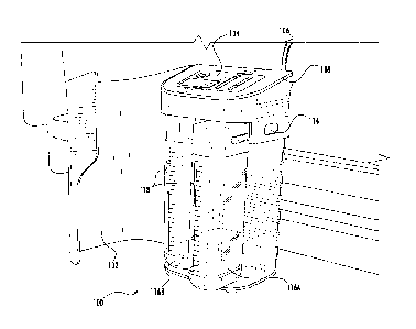
Referring to FIG. 3A and FIG. 3B, in some embodiments, as described
above, the housing of the smart catheter 100 can comprise a door 102
configured to open in any suitable direction. For example and without
limitation, the door 102 can be hingedly attached to the housing and open up
(i.e., like an overhead storage bin in an aircraft) or the door 102 could open
out, laterally (i.e., like a typical door). Although the embodiments disclosed
in
the figures depict a door 102 that is painted, translucent, or non-transparent
to obscure the contents of the collection reservoirs 116, in some
embodiments, the door 102 can be clear or transparent so that medical staff
can easily visually monitor the contents of the collection reservoirs 116. In
some embodiments, the housing of the smart catheter 100 can comprise one
or more collection reservoirs 116 inside. For example and without limitation,
the smart catheter 100 can comprise a first collection reservoir 116A and a
second collection reservoir 116B, each configured to collect urine or other
fluid
as shown in FIG. 3A. As depicted in FIG 3A, the first collection reservoir
116A
and the second collection reservoir 116B can comprise, for example, and
without limitation, vials, bags, jars, or any suitable container or reservoir
for
containing the urine. In some embodiments, each of the first collection
reservoir 116A and the second collection reservoir 116B can comprise
graduated markings 118 on them to help indicate how full they are for a
healthcare worker to manually verify their fill levels. In some embodiments,
each of the collection reservoirs 116 can be transparent or non-transparent,
For example, if medical staff is required to visually monitor the contents of
the
collection reservoirs 116, they can be transparent.
As illustrated in FIG. 3B, in some embodiments, the housing of the
smart catheter 100 can comprise one or more push buttons 114 to eject one
or more of the collection reservoirs. For example and without limitation, in
some embodiments, there can be one push button 114 for every collection
reservoir or there can be a different push button 114 for each collection
reservoir. In some embodiments, the push button 114 and the one or more
collection reservoirs 116 can be configured and positioned such that any of
the one or more collection reservoirs 116 can be removed using only one
hand. For example and without limitation, in some embodiments, the push
-14-
Date Recue/Date Received 2023-05-30
button 114 can be positioned such that a finger of the hand grasping the body
of the collection reservoir 116 can also press the push button 114 to release
the collection reservoir 116. As shown in FIG. 3B, one or more of the
collection
reservoirs, such as for example first collection reservoir 116A, is capable of
being removed for inspection, emptying, replacement, or any other suitable
purpose.
Referring to FIG. 4A and FIG. 4B in some embodiments, the collection
reservoir 116 can comprise a total dissolved solids (TDS) meter 120 or sensor
configured for measuring the total dissolved solids in the urine. In some
embodiments, the TDS meter 120 is in communication with the one or more
processors of the smart catheter 100, wherein the one or more processors is
configured to use the TDS meter 120 to capture total dissolved solids
measurements of the urine and relay that data or perform various tasks with
that data. For example and without limitation, based on outputs from the TDS
meter 120, the one or more processors can be configured to transmit statistics
about this data to health provider software, or provide outputs on the display
102. This information can then be used to ensure that the health of the
patient
is being monitored.
Additionally, in some embodiments, one or more color sensors 122, for
example and without limitation an RGB sensor can be provided in the
collection reservoir 116. In some embodiments, the one or more color sensors
122 can be used to detect and measure a color or shade of the urine. This
information can be used to determine the health of the patient, for example,
determining whether the patient is dehydrated and needs more fluids or
electrolytes, or is bleeding, etc. In some embodiments, the TDS meter 120
and/or the one or more color sensors 122 can be in communication with the
one or more processors via a wired or wireless connection and can transmit
and receive data and instructions, respectively, regarding their functions and
output captures.
FIG. 4B depicts the rear of an example collection reservoir 116, each
of the collection reservoirs 116 comprising a quick connect port 124 that
allows it to quickly connect to the smart catheter 100. The quick connect port
124 can be configured to allow fluid, including urine, to drain and collect
into
-15-
Date Recue/Date Received 2023-05-30
the collection reservoir 116 from the flexible tube 106 that connects to the
top
of the housing. Although not depicted in the figures, the smart catheter 100
of
the present disclosure can comprise an infrastructure inside the housing that
connects the flexible tube 106 to the quick connect port 124. In some
embodiments, the infrastructure inside the smart catheter 100 can comprise a
switch or electric valve which can be configured to select which of the one or
more collection reservoirs 116 the flexible tube 106 drains into. In some
embodiments, the one or more processors is configured to operate the
infrastructure, including the one or more switches or electric valves. In this
case, either automatically or manually, the processor is configured to actuate
the switch or electric valve to select which collection reservoir 116 is to
receive
urine. For example and without limitation, once the first collection reservoir
116A gets full or to a certain level, the processor is configured to actuate
the
switch or valve such that urine or other fluid starts draining into the second
collection reservoir 116B. Additionally, if there is a malfunction in a
collection
reservoir 116, or for some other reason, the smart catheter 100 is configured
to allow medical staff to manually select a different collection reservoir 116
and the switch will be actuated to change to the other reservoir. In some
embodiments, if the collection reservoir 116 currently being drained into is
removed from the device, the smart catheter 100 is configured to automatically
move over to any of the other available collection reservoirs 116 that are not
themselves already full or malfunctioning.
Additionally, one or more collection reservoirs 116 comprises an
electrical connection 128 configured to not only help power the various
sensors, meters, and other components within the one or more collection
reservoir 116, but also to connect the one or more processors to the various
sensors, meters, and other components for performing the actions described
herein. For example, and without limitation, each of the TDS meter 120
outputs and the one or more color sensors 122 can measure their respective
characteristics of the urine or other fluid in the collection reservoir and
then
transmit those measurements to the one or more processors via the electrical
connection 128. This action can be performed automatically by the sensors
themselves (i.e., without any request or query from the processor) or the one
-16-
Date Recue/Date Received 2023-05-30
or more processors can query the sensors at a constant, periodic, or random
time, or, a medical professional could manually request a check of the outputs
of the sensors via the display 104 or other computing equipment that is in
communication with the smart catheter 100.
In some embodiments, the electrical connection 128 can be used by
the smart catheter 100 to communicate with the collection reservoir 116 to
determine a fluid level of the collection reservoir 116. In some embodiments,
the smart catheter 100 is configured to alarm when at least one of the
collection reservoirs 116 is at least half-way full. Furthermore, in some
embodiments, the smart catheter 100 is configured to alarm when there is no
urine output or not sufficient urine output. These can be set parameters as
well. In some embodiments, the alarm could be, for example and without
limitation, a signal, message, text message, electronic message, electronic
mail, or other appropriate message sent to medical professional mobile
devices, tablets, computers, or mobile work stations so that they will be
informed of the alarm. Any messages, alarms, or warnings sent via textual or
electronic message can include such information as the type of warning, how
much of the collection reservoir 116 is full, what its fill level is at, and
any other
relevant information such as the associated patient, hospital room, or other
suitable identifier.
In some other embodiments, the alarm could be, for example a sound
made by the smart catheter 116 via a speaker (not shown). In some
embodiments, the smart catheter 100 is configured such that it can alarm
using an automated voice such as "RESERVOIR FULL", "ALL RESERVOIRS
FULL", "RESERVOIR HALF FULL", "RESERVOIR IS X% FULL" (X being any
percentage), or any other programmable automated voice sound. In some
embodiments, every time urine is deposited into one or more reservoirs, the
smart catheter 100 can be configured to alert any of the voice alarms above.
In some embodiments, the alarm could be a beep or other sound that occurs
once or a few times just to alert the medical professionals working with the
patient that the collection reservoir 116 is halfway full. In some
embodiments,
the smart catheter 100 is configured to trigger an alarm when at least one of
the collection reservoirs 116 is almost full and there is only a selectively
-17-
Date Recue/Date Received 2023-05-30
predetermined volume left, such as 100m1, before the collection reservoir 116
is completely full. In this particular case, the alarm indicating that the
collection
reservoir 116 is almost full can be a different sound or have some other
indicia
(e.g., different tune, different number of beeps, etc.) that indicates that it
is a
different alarm than the one indicating that the collection reservoir 116 is
halfway full. In a similar fashion, if a predetermined minimum threshold of
urine
has not been collected by the smart catheter 100, as described herein, then
an alarm, like those described herein, can be triggered. In some
embodiments, if the amount of urine that is collected by the smart catheter
100, as described herein, does not fall within a certain predetermined
threshold within a specific amount of time, then an alarm can be triggered, as
described herein. In some embodiments, the system will notify of critical
values or when set parameters are exceeded. These parameters can be
patient specific and thus can be altered or customized by the healthcare
officials via the display 104 or via transmissions to the one or more
processors
on board the smart catheter 100.
In some embodiments, when only a single collection reservoir 116 is
inserted in the smart catheter 100, once it is completely full, a similar
alarm to
those described above will sound and/or appropriate electronic messages
described above will be sent. In some embodiments, the smart catheter 100
is configured such that any alarm conveying a sound such as a beep or other
alarm sound will continue to alarm until the collection reservoir 116 is
exchanged or until the smart catheter 100 is turned off (e.g., if the patient
is
no longer hooked up to the smart catheter 100). Similarly, if the smart
catheter
100 comprises more than one collection reservoir 116, such as the two
collection reservoirs 116A and 116B in FIG. 3A and FIG. 3B, the alarm that
continuously sounds or alerts will do so when all of the collection reservoirs
116 are full. In some embodiments, these limits described hereinabove can
be set and adjusted by medical staff monitoring the smart catheter 100 to
address differences in patients and differences in the size of potential
collection reservoirs 116. For example and without limitation, the alarms can
sound off at any particular set limit and more than three alarms can be set.
For example and without limitation, a plurality of alarms can be set to
trigger
-18-
Date Recue/Date Received 2023-05-30
at various fill levels of the collection reservoir 116. The lengths, sounds,
chirps,
messages, etc. can all be modified or changed to help medical staff to
differentiate between which alarm goes to which fill level. All of the alarms,
measurements, and other various features of the smart catheter 100 are
customizable and adjustable and has sufficient memory and storage to be
able to have a plurality of predetermined and preset limits and alarms.
Additionally, in some embodiments, when the smart catheter 100
detects a malfunction with the connection to one or more of the collection
reservoirs 116 (or any of the sensors or meters therein), or a malfunction of
the display 104, lighting element 108, or any other component of the smart
catheter 100, an alarm is configured to be triggered, similar to the alarms
described above. In some embodiments, if possible the lighting element 108
can flash a different color if the malfunction has to do with the display 104
or
if the malfunction is such that the display 104 cannot be powered or, if the
display 104 can be powered, an error message indicative of the malfunction
can be displayed on the display 104.
As illustrated in FIG. 4B, in some embodiments, the collection reservoir
116 can comprise a groove to locate and hold the collection reservoir 116.
Although they are depicted herein as substantially cylindrical, those having
ordinary skill in the art will appreciate that the collection reservoirs 116
and
thus, the shape of the smart catheter 100 can be of any suitable shape and
size. For example, the collection reservoirs 116 can be flask shaped,
cylindrical, bag shaped, bowl shaped, cube shaped, shaped like a rectangular
prism, or any suitable three-dimensional shape that can collect and hold
fluid.
The smart catheter 100 can be modified from the shape illustrated in the
present figures to fit any shape described above or any three-dimensional
shape.
FIG. 5 illustrates an exploded view of an example collection reservoir
116 of the present disclosure. In some embodiments, the collection reservoir
116 comprises an inlet port 132 that connects to the infrastructure of the
smart
catheter 100 via the quick connect port 124. In some embodiments, the inlet
port 132 connects to the switch or electronic valve that determines or selects
which collection reservoir 116 is meant to receive urine or other fluid at the
-19-
Date Recue/Date Received 2023-05-30
current time. Once the collection reservoir 116 is properly inserted into the
smart catheter 100 and the quick connect port 124 is connected to the
infrastructure of the smart catheter 100 and the particular collection
reservoir
116 is selected to receive urine, the urine flows through the inlet port 132
to
the flow meter 130 which is configured to measure the amount of urine that is
collected in the collection reservoir 116. Once the urine flows through the
flow
meter 130, it flows out the egress port 134 and into the spout 136 of the
collection reservoir 116. In some embodiments, the flow meter 130 is
configured to measure the volume of urine that flows through it via any
suitable
means. For example and without limitation, in some embodiments, the flow
meter 130 is configured to calculate the flow rate by determining the number
of milliliters of fluid per second (or other suitable volume per time period)
that
flows into the collection reservoir 116 and multiply that by the number of
seconds that it detects urine flowing at the given rate. In some embodiments,
the flow meter 130 can use more or less accurate measurements of the flow
rate to determine a more precise volume of urine in the collection reservoir
116. In some embodiments, the flow meter 130 can be a part of the flexible
tube 106 itself and not part of the collection reservoir 116. In other words,
the
flow meter 130 can be positioned at any suitable location along the flexible
tube 106. Furthermore, the flow meter 130 can be integrated into the flexible
tube 106 or be a separate piece as shown in FIG. 5. In such an instance where
the flow meter 130 is positioned outside of the housing, the flow meter 130 is
still in communication with and subject to instructions from the one or more
processors via wireless or wired connection.
Referring to FIG. 6A and FIG. 6B, in some embodiments, the smart
catheter 100 can comprise one or more rubber feet 138 on the bottom of the
device such that if the device were positioned on a surface, any sliding of
the
device would be minimized. Additionally, as illustrated in FIG. 6B, in some
embodiments, the clamp and/or bracket 112 on the back can be rotated such
that the opening of the clamp and/or bracket 112 is either parallel to the
length
of the housing of the smart catheter 100 or perpendicular to the length of the
housing of the smart catheter 100. Those having ordinary skill in the art will
appreciate that the clamp and/or bracket 112 can be adjusted up or down
-20-
Date Recue/Date Received 2023-05-30
along a track on the back of the smart catheter 100 as well. Moreover, in some
embodiments, the clamp and/or bracket 112 is rotatable in place and doesn't
need to be removed in order to rotate it to be parallel with or perpendicular
with respect to the smart catheter 100. Furthermore, in some embodiments,
the clamp and/or bracket 112 can be configured to mount the smart catheter
100 to a standard hospital bed frame, transport poles, or any other suitable
location. For example and without limitation, the clamp or bracket 112 can be
configured to attach the smart catheter 100 housing or enclosure to a bed or
other frame, pole, or other suitable attachment point with dimensions of .Y2",
1", 1 1/2", 2", 21/2", etc.
Referring to FIG. 7, in some embodiments, the smart catheter 100 of
the present disclosure is configured to present various pieces of information
on the display 104. For example and without limitation, the display 104 can be
configured to show information identifying the patient for which the
particular
smart catheter 100 is being used for. Such identifying information could be a
picture 140 or avatar of the patient or the patient's name 142, or patient
identification number. In addition, in some embodiments, fluid levels 144 or
capacities of each collection reservoir 116 can be displayed. In some
embodiments, the one or more processors situated within the housing of the
smart catheter 100 can control what and when items are displayed. In some
embodiments, the alarms described herein can coincide with various
indicators flashing on the display 104 to help alert healthcare workers of the
issue. Additionally, in some embodiments, the display can flash the fluid
level
144 indicator of one more of the collection reservoirs 116 when they have
reached certain thresholds. In this way, medical staff can easily determine
which collection reservoir 116 is full before even opening up the door 102. In
some embodiments, the display 104 can also show pertinent information
about the urine, such as for example, any dissolved solids statistics or other
information. In some embodiments, the display 104 is configured to light up to
match the color of the urine. In some further embodiments, the display 104
has the ability to have sensor motion to turn the light on from dim to bright.
Those having ordinary skill in the art will appreciate that the display 104
can be configured to display any appropriate information that relates to the
-21-
Date Recue/Date Received 2023-05-30
patient, medical workers, the status of the smart catheter 100 or any of its
parts, etc. To allow a medical professional who is operating and monitoring
the smart catheter 100 to have easier control over the device, the display 104
can be a touchscreen display that has multiple different pages, folders, and
buttons that can be displayed, changed, altered, customized, etc.
Additionally,
in some embodiments, the one or more processors can be in communication
with one or more external devices. In some embodiments, the external
devices comprises servers or other computers hosting the patient's medical
records and/or medical chart. In such an embodiment, the one or more
processors can be configured to automatically measure the amount or volume
of urine according to predetermined sets of time (e.g., continuously,
periodically, randomly, every 30 minutes or Q one hour, etc.) in one or more
of the collection reservoirs 116 and transmit a volume of urine in total or in
each of the collection reservoirs 116. Additionally, information about the
urine
gleaned from the various sensors can also be recorded and sent to the
medical records and/or medical chart for updating.
Moreover, in some embodiments, the external device comprises a
tablet, computer, mobile device, phone, smart watch, audio device, handheld
documentation device or display device. In some embodiments such a
catheter as provided herein further comprises a power source, a computer,
memory, a receiver or transmitter, an accelerometer, a speaker, microphone,
or a tactile signal device, wherein the power source, computer, memory,
receiver or transmitter, accelerometer, speaker or tactile signal device are
interconnected with one another. In some embodiments such a catheter as
provided herein further comprises a computer program product comprising
computer executable instructions embodied in a computer readable medium
for performing steps comprising receiving an electrical signal from a
measuring apparatus, processing the electrical signal to calculate data
pertaining to a measured volume, and relaying the data to the electronic
display, speaker, tactile signal device or external device. In some
embodiments, a wireless receiver is configured to receive data wirelessly and
transfer it to a computer, wherein the computer is configured to process the
data and transmit it to the display, speaker or tactile signal device.
-22-
Date Recue/Date Received 2023-05-30
The functions and subject matter described herein, especially with
respect to the one or more processors described herein, can in some
embodiments be implemented using a computer program product comprising
computer executable instructions embodied in a computer readable medium.
Such computer readable medium can be stored in memory and implemented
by computer. Exemplary computer readable media suitable for implementing
the subject matter described herein include disk memory devices, chip
memory devices, application specific integrated circuits, programmable logic
devices, and downloadable electrical signals. In addition, a computer program
product that implements the subject matter described herein may be located
on a single device or computing platform or may be distributed across multiple
devices or computing platforms.
All of the above measurements and transmissions can be done in real
time or after the fact (i.e., as soon as urine flows and stops flowing into
the
collection reservoir 116, the smart catheter 100 can transmit the volume data
and urine characteristics data to the medical records server). In some
embodiments, the smart catheter 100 can comprise a transmitter,
transmission device, or transceiver for making a wired or wireless connection
to the medical records and/or medical chart server/computer. Moreover, in
some embodiments, the smart catheter 100 comprises a receiver, such as, for
example and without limitation, a wireless or wired receiver configured to
receive data from an external device. Using the one or more processors and
transmitter and/or receiver, any component of the smart catheter 100 can
receive or transmit data to/from any suitable external or internal device
(i.e.,
such as the medical records or medical chart server, mobile phones, tablets,
medical equipment, etc.). A wireless receiver and/or transmitter can be
configured to wirelessly receive and/or transmit data and information via
wireless signal. By way of example and not limitation, such wireless forms of
communication can comprise Wi-Fi and Bluetooth. As described herein, with
integrated wireless communication capabilities, catheters can exchange
information and/or data, i.e. receive and/or transmit, with another device,
such
as but not limited to a tablet, computer, phone, smart watch, audio device or
display device.
-23-
Date Recue/Date Received 2023-05-30
In some embodiments, the smart catheter 100 can be powered by a
wired power cable connected to an electrical outlet. In further embodiments,
the smart catheter 100 can be powered by a battery or other suitable power
source. In either embodiments, the smart catheter 100 can be configured to
trigger and sound an alarm as described herein when either the power
connection is inadequate, or there is a malfunction with the power connector
or the battery or other power source. Additionally, in some embodiments, the
smart catheter 100 can be operable using speech recognition. In support of
this feature, some embodiments of the smart catheter 100 of the present
disclosure comprise speakers and an audio input device, such as a
microphone, that allow a user to speak to the smart catheter 100 to issue
commands or requests. Moreover, in such an embodiment, the one or more
processors of the smart catheter 100 can be configured to operate an
artificial
intelligence program that is configured to receive spoken commands and
respond with additional audio feedback or perform tasks in connection with
the commands. In this way, any of the parameters, actions, services, or
performances that can be performed automatically, or manually be a person
touching the smart catheter 100 can also be performed via voice command
using speech recognition.
Smart Chest Tube
In some embodiments of the present disclosure, the smart catheter 100
can be retrofitted to act as a smart chest tube, instead. Provided herein are
smart chest tubes, also referred to herein as precise chest tubes, KG chest
tubes, chest tubes and/or electronic chest tubes. A chest tube is a flexible
plastic tube that is inserted through the chest wall and into the pleural
space
or mediastinum. It is used to remove air, fluid, pleural effusion, blood,
chyle,
or pus from the intrathoracic space. It is also known as a Biilau drain or an
intercostal catheter.
In some cases, pressure around the lungs is lower than atmospheric
pressure outside the body. The aims for an adequate chest drainage system
to be fulfilled are: (i) remove fluid and air as promptly as possible; (ii)
prevent
-24-
Date Recue/Date Received 2023-05-30
drained air and fluid from returning to the pleural space, restore negative
pressure in the pleural space to re-expand the lung. Thus, in some
embodiments, a drainage device can: (i) allow air and fluid to leave the
chest;
(ii) contain a one-way valve to prevent air and fluid from returning to the
chest;
(iii) comprise a design so that the device is below the level of the chest
tube
for gravity drainage. An underwater seal chest drainage system can be used
to restore proper air pressure to the lungs, re-inflate a collapsed lung as
well
as remove blood and other fluids. The system is a two-chambered or three-
chambered plastic unit with vertical columns bringing measurements marked
in milliliters. The thoracic drainage devices cover a wide range and have
evolved considerably since their introduction. The basic design principle of
these systems has been the avoidance of air entrance in the pleural cavity
during the various phases of the respiratory cycle and continuous drainage of
air and fluid from the pleural cavity. The water seal chamber, which is
connected in series to the collection chamber, allows air to pass down through
a straw or narrow channel and bubble out through the bottom of the water
seal. Since air must not return to the patient, a water seal is considered one
of the safest and cost-effective means for protecting the patient, in addition
to
being a very useful diagnostic tool. The water seal column is calibrated and
acts as a water manometer for measuring intrathoracic pressure.
In a traditional water seal operating system, fluids drain from the patient
directly into a large collection chamber via a tube, e.g. a six-foot 3/8-inch
tube.
As drainage fluids collect in this chamber, a nurse or other practitioner can
record the amount of fluid that collects on a specified schedule.
Unfortunately,
the measuring and recording of the drainage fluid is still done manually. What
is needed is an automated and accurate measurement and recording device.
Referring to FIG. 8, in some embodiments, the smart chest tube of the
present disclosure can look virtually identical to the smart catheter 100 of
FIG.
1 ¨ FIG. 7 and have virtually all the same components. However, for a smart
chest tube, additional components are required, as those having ordinary skill
in the art will fully appreciate. These components are well known in the art.
Specifically, the measuring devices, sensors, and other pieces of equipment
described hereinabove can be altered to be able to receive and measure air,
-25-
Date Recue/Date Received 2023-05-30
fluid, pleural effusion, blood, chyle, or pus flowing from the intrathoracic
space
through the chest tube. The flexible tube 106 can be replaced or altered to
operate as a chest tube, wherein the flexible tube 106 comprises one or more
openings at one end 106-1, and a drainage port at the opposing end. In some
embodiments, the one or more openings 106-1 can be located at the end face
of the flexible tube 106, or they can be axially aligned, meaning they run
down
the length of the flexible tube 106, starting near the end. In some other
embodiments, the one or more openings 106-1 can be circumferentially
aligned, meaning around the circumference of the flexible tube 106.
In some embodiments, the flow meter 130 of FIG. 5 is configured to
measure an amount of air, fluid, pleural effusion, blood, chyle, and/or pus
flowing therethrough, instead of urine. The flow meter 130 can be adapted to
properly measure almost any fluid flowing therethrough.
The measured volume of air, fluid, pleural effusion, blood, chyle, or pus
determined by the flow meter 130 can be transmitted as data to an external
device, e.g. a computer or receiver. As described herein, the smart chest tube
device can in some embodiments comprise a transmitter or transmission
device to wirelessly transmit the data to an external device. The smart chest
tube can in some embodiments also comprise a receiver configured to receive
data from an external device.
In some embodiments, when the device is retrofitted as a smart chest
tube, the device is configured to measure and calculate the volume of air,
fluid,
pleural effusion, blood, chyle, or pus produced by a patient and activate an
alarm if such volume output exceeds or does not meet a set or predetermined
threshold, or as described above, if the collection reservoirs 116 are full,
about
to be full, or if there is a malfunction. All of the features and aspects
described
above with respect to the smart catheter 100 can be retrofitted and slightly
altered to account for any differences in the operations of a urinary catheter
versus a chest tube. For example, tubes and ports sizes can be increased and
materials can be altered to make it more available for puss and chyle storage.
Additionally, for the smart chest tube application, the smart catheter
100 as described herein can be retrofitted with a suction control chamber to
help suction the fluid being drained from the chest cavity of the patient.
-26-
Date Recue/Date Received 2023-05-30
The present subject matter can be embodied in other forms without
departure from the spirit and essential characteristics thereof. The
embodiments described therefore are to be considered in all respects as
illustrative and not restrictive. Although the present subject matter has been
described in terms of certain specific embodiments, other embodiments that
are apparent to those of ordinary skill in the art are also within the scope
of
the present subject matter.
-27-
Date Recue/Date Received 2023-05-30