Note: Descriptions are shown in the official language in which they were submitted.
CA 03144276 2021-12-17
WO 2020/264057
PCT/US2020/039464
ULTRA¨LOW WASTE DISPOSABLE SAFETY SYRINGE FOR LOW
DOSE INJECTIONS
Technical Field Of The Invention
In general, the present invention relates to
syringes that are used to make injections through a
needle or cannula. More particularly, the present
invention relates to safety syringes that are
designed to shield the needle after use and to
minimize the amount of injection material retained
within the syringe after the syringe is used.
Background Art
Healthcare professionals perform millions of
injections each year. The injections are typically
performed using a hypodermic needle and a syringe.
The length of the hypodermic needle and the gauge of
the needle depend upon the application and whether
the injection is intramuscular, subcutaneous,
intravenous, or intradermai. The compounds being
injected also vary widely. Some injection materials,
such as saline, are very inexpensive. However, many
pharmaceutical compounds, such as certain gene
therapy compounds, can cost tens of thousands of
dollars per injection. As such, a fraction of a
milliliter of the pharmaceutical can be worth
hundreds of dollars.
1
CA 03144276 2021-12-17
WO 2020/26-1057
PCT/US2020/039464
When a traditional hypodermic needle and
syringe are used to perform an injection, there is
inevitably some volume of injection material that
remains within the needle and syringe after the
injection is complete. The pharmaceutical material
remaining is thrown away with the needle and syringe
after the injection. This wasted pharmaceutical
material adds up to billions of dollars in wasted
pharmaceuticals, when all injections are considered.
In the prior art, thought is rarely given to
the volume of residual material that inherently
remains within a hypodermic syringe and needle. Some
needle and syringe assemblies have been designed
where a syringe plunger and a needle head make flush
contact. Such prior art designs are exemplified by
U.S. Patent No. 6,616,636 to Lee and U.S. Patent No.
5,902,270 to Jentzen. However, in a real healthcare
environment, such as a hospital, different syringes
are used with many different needle heads, depending
upon the specific medical application. Some needle
head and syringe combinations are efficient in the
discharge of pharmaceutical compounds and some are
not.
The problem becomes more complicated when a
needle head and syringe are part of a safety syringe
assembly. Safety syringe assemblies are designed to
2
CA 03144276 2021-12-17
WO 2020/264057
PCT/US2020/039464
both perform an injection and to provide some
mechanism for minimizing the likelihood of a needle
stick injury. Needle stick injuries are commonplace
among healthcare workers. Needle stick injuries are
defined by the United States National Institute of
Occupational Safety and Health as injuries caused by
needles such as hypodermic needles, blood collection
needles, intravenous (IV) stylets, and needles used
to connect parts of IV delivery systems. Needle
stick injuries can transfer blood-borne pathogens
such as Hepatitis B virus, Hepatitis C virus, Human
Immunodeficiency Virus (HIV) and Covid-19. For
healthcare workers, needle stick injuries are
responsible for a significant proportion of these
diseases in the healthcare workforce.
It has been estimated by the Centers for
Disease Control, that in the United States of
America, that more than three million healthcare
workers are exposed to blood and bodily fluids via
needle mishaps each year. Most healthcare workers
are trained in procedures for using and disposing of
used needles. For example, needles should not be
recapped, in order to prevent the potential for
needle stick injuries. However, many studies have
revealed that recapping is still prevalent among
healthcare workers.
3
CA 03144276 2021-12-17
WO 2020/264057
PCT/US2020/039464
In an attempt to reduce the number of needle
stick injuries, various safety needles have been
developed that act to automatically cover a needle
the instant the needle is retracted from the skin.
This is typically accomplished by advancing a
tubular sheath along the shaft of the needle until
the sheath covers the tip of the needle. Such prior
art is exemplified by U.S. Patent No. 6,626,863,
U.S. Patent Application Publication No.
2007/0016140, U.S. Patent Application Publication
No. 2007/0016145, and U.S. Patent Application
Publication No. 2008/009808. However, integrating a
safety mechanism within a needle head typically
takes additional room within the needle head. More
room in the needle head means that there is more
dead space in the needle head where residual
pharmaceutical compounds can collect. As a
consequence, there are often opposing concerns that
must be balanced in a design. The safety features of
a design are balanced with the wasted pharmaceutical
retained because of the safety features.
A need therefore exists for an improved
hypodermic needle and syringe assembly where the
needle is automatically shielded after an injection
and wherein the assembly does not retain any
significant volume of the material being injected.
4
CA 03144276 2021-12-17
WO 2020/264057
PCT/US2020/039464
This need is met by the present invention as
described and claimed below.
DISCLOSURE OF THE INVENTION
The present invention is a needle and syringe
system, wherein a needle head is attached to a
syringe assembly. The syringe assembly includes a
syringe barrel. A plunger rod is provided with a
plunger head that can reciprocally move within the
syringe barrel.
A needle base is affixed to the syringe barrel.
The needle base has a first end and a second end at
opposite points along a central axis. A tubular
cavity is formed in the needle base and a post
extends through the tubular cavity. The tubular
cavity is accessible from the first end of the
needle base.
A needle extends into the needle base along the
central axis. The needle extends through the post
and is open at the first end of the needle base to
receive the contents of the syringe barrel. A spacer
is provided. The spacer is displaced into the
tubular cavity within the needle base as the plunger
head is advanced within the syringe barrel.
A protective cover is disposed about the needle
base. The spacer moves the protective cover between
5
CA 03144276 2021-12-17
WO 2020/264057
PCT/US2020/039464
a first position and a second position as the spacer
is displaced into the tubular cavity. As the
protective cover moves between positions, the
protective cover surrounds the needle and prevents
the needle from causing any inadvertent needle stick
injuries.
BRIEF DESCRIPTION OF THE DRAWINGS
For a better understanding of the present
invention, reference is made to the following
description of an exemplary embodiment thereof,
considered in conjunction with the accompanying
drawings, in which:
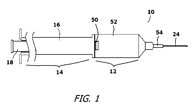
FIG. 1 shows the head of an exemplary needle
and syringe system in a condition ready for use with
its needle exposed;
FIG. 2 is a cross-sectional view of the
embodiment of Fig. 1;
FIG. 3 shows an exploded view of the exemplary
embodiment;
6
CA 03144276 2021-12-17
WO 2020/264057
PCT/US2020/039464
FIG. 4 is a cross-sectional view of the
exemplary embodiment with the needle partially
covered by the protective cover; and
FIG. 5 is a cross-sectional view of the
exemplary embodiment with the needle fully covered
by the protective cover.
DETAILED DESCRIPTION OF BEST MODE FOR CARRYING OUT
THE INVENTION
The present invention needle and syringe system
can be configured in many ways and can be adapted
for use in many applications. However, only one
exemplary embodiment is selected for the purposes of
description and illustration. The illustrated
embodiment, however, is merely exemplary and should
not be considered a limitation when interpreting the
scope of the appended claims.
Referring to Fig. 1, Fig. 2, and Fig. 3, the
present invention needle and syringe system 10 is
shown. In the shown embodiment, the needle and
syringe system 10 includes two primary subassemblies
that are selectively joined. The primary
subassemblies include a head subassembly 12 and a
syringe subassembly 14. The head subassembly 12
7
CA 03144276 2021-12-17
WO 2020/264057
PCT/US2020/039464
mechanically engages the syringe subassembly 14 with
a mechanical connection, or can be bonded to the
syringe subassembly 14 using adhesive or a plastic
weld. Regardless, the connection between the syringe
subassembly 14 and the head subassembly 12 is fluid
impervious.
The syringe subassembly 14 includes a syringe
barrel 16 and a plunger rod 18 that extends into the
syringe barrel 16. The plunger rod 18 can be
manually advanced through the syringe barrel 16
toward the head subassembly 12. The plunger rod 18
terminates with an elastomeric piston head 20. The
elastomeric piston head 20 seals against the
interior of the syringe barrel 16 as the plunger rod
18 moves within the syringe barrel 16. The piston
head 20 has a flat front surface 22 that faces the
piston head 20 in the syringe barrel 16.
The head subassembly 12 holds a needle 24. The
needle 24 is supported in the head subassembly 12 by
a plastic needle base 26. The needle base 26 has a
complex shape. The needle base 26 is symmetrically
formed around a central axis 28, wherein the needle
24 is aligned with the central axis 28. Along the
central axis 28, the needle base 26 has a first end
30 and an opposite second end 32. The first end 30
8
CA 03144276 2021-12-17
WO 2020/264057
PCT/US2020/039464
of the needle base 26 extends into the syringe
barrel 16 and faces the piston head 20.
A flange 34 is formed near the first end 30 on
the exterior of the needle base 26. The flange 34 is
either mechanically connected, or adhered to, the
syringe barrel 16. This joins the needle base 26 to
the syringe barrel 16. Two locking depressions 36,
38 are formed on the exterior of the needle base 26.
The first locking depression 36 is positioned near
the first end 30 of the needle base 26 and the
second locking depression 38 is positioned near the
second end 32 of the needle base 26.
A tubular cavity 40 is formed in the first end
30 of the needle base 26. The tubular cavity 40 is
accessible through two side slots 42 that are formed
in opposite sides of the needle base 26. The slots
42 extend from the flange 34 to the distal end of
the tubular cavity 40. The tubular cavity 40 is also
accessible from within the syringe barrel 16. The
tubular cavity 40 creates a central post 44 within
the needle base 26, wherein the central post 44 is
concentric with the central axis 28. The needle 24
extends through the central post 44, therein
enabling the needle 24 to access the contents of the
syringe barrel 16. The central post 44 has a length,
9
CA 03144276 2021-12-17
WO 2020/264057
PCT/US2020/039464
which is longer than the length of the tubular
cavity 40. As a result, the central post 44
partially extends into the syringe barrel 16.
An annular spacer 46 and an activation ring 48
are provided. In the shown embodiment, the annular
spacer 46 and the activation ring 48 are shown as
separate components. This is an optional
configuration. The annular spacer 46 and the
activation ring 48 can be molded as a single piece.
In the shown two-piece construction, the annular
spacer 46 is tubular in shape, with inner and outer
diameters that enables the annular spacer 46 to fit
within the tubular cavity 40 of the needle base 26.
The activation ring 48 has an annular body 49 and
two radial supports 50 that extend outwardly from
the annular body 49. The annular body 49 has the
same inner diameter and outer diameter as the
annular spacer 46. The radial supports 50 are wide
enough to extend into the side slots 42 of the
needle base 26. The combined length of the annular
spacer 46 and the activation ring 48 are exactly the
same as the length of the central post 44. The
annular spacer 46 and the activation ring 48 are
free to slide along the length of the central post
44, as limited by the movement of the radial
supports 50 in the side slots 42.
CA 03144276 2021-12-17
WO 2020/264057
PCT/US2020/039464
The head subassembly 12 includes a protective
cover 52 that is in place over the needle base 26.
The protective cover 52 has a safety sheath 54 that
surrounds part of the needle 24. The protective
cover 52 can reciprocally move along the exterior of
the needle base 26. However, the protective cover 52
contains an inwardly extending locking protrusion 56
that can engage the locking depressions 36, 38 on
the exterior of the needle base 26. When the locking
protrusion 56 moves into one of the locking
depressions 36, 38, the protective cover 52 becomes
biased into a set position.
Prior to use, the head subassembly 12 has the
configuration shown in Fig. 2. Referring to Fig. 4
and Fig. 5 in conjunction with Fig. 3, it can be
seen that prior to use, the syringe barrel 16 is
filled with a medication 55 in the traditional
manner. In this first position, the syringe barrel
16 is full and locking protrusion 56 on the
protective cover 52 engages the first locking
depression 36 on the needle base 26. This prevents
any inadvertent discharge from occurring while the
needle and syringe system 10 is being handled. As
the plunger rod 18 is manually advanced, the locking
protrusion 56 can be displaced from the first
locking depression 36. As the piston head 20
11
CA 03144276 2021-12-17
WO 2020/264057
PCT/US2020/039464
advances toward the head subassembly 12, the piston
head 20 contacts the annular spacer 46 and presses
both the annular spacer 46 and the activation ring
48 into the tubular cavity 40 around the central
post 44 of the needle base 26. As the piston head 20
contacts the central post 44, the annular spacer 46
and the activation ring 48 completely fill the
tubular cavity 40. All medication is displaced from
the syringe subassembly 14 except for the
exceedingly small volume that remains inside the
needle 24. At this second position, the locking
protrusion 56 engages the second locking depression
38 on the needle base 26.
As the plunger rod 18 is advanced, the plunger
rod 17 contacts and moves the annular spacer 46. The
annular spacer 46 moves the activation ring 48. The
radial supports 50 on the activation ring 48 extend
into the side slots 42 in the protective cover 52.
As the activation ring 48 is pressed forward by the
advancing annular spacer 46, the radial supports 50
move the protective cover 52 forward on the needle
base 26. As the protective cover 52 moves forward,
the safety sheath 54 also moves forward, wherein the
safety sheath 54 covers the tip of the needle 24.
The activation ring 48 and the radial supports 50
move along the needle 24 during the injection. As a
12
CA 03144276 2021-12-17
WO 2020/264057
PCT/US2020/039464
result, the safety sheath 54 also moves forward
during the injection. By the time the injection is
complete, the safety sheath 54 is fully advanced and
the needle 24 becomes fully shielded. As a
consequence, there is no opportunity after the
injection for a healthcare provider to contact the
tip the needle 24.
A colored indictor 60 may be provided on the
exterior of the needle base 26 to provide a color-
coded indication that the needle and syringe system
10 has moved from its full first position to its
discharged second position.
It will be understood that the embodiment of
the present invention that is illustrated and
described is merely exemplary and that a person
skilled in the art can make many variations to that
embodiment. All such embodiments are intended to be
included within the scope of the present invention
as defined by the appended claims.
13