Note: Descriptions are shown in the official language in which they were submitted.
POSTURAL PLATFORM TRAINING DEVICE
CROSS-REFERENCE TO RELATED APPLICATIONS
[0001] This application claims the benefit of the filing date of U.S.
Provisional Patent
Application No. 62/867,383 filed June 27, 2019.
BACKGROUND OF THE INVENTION
[0002] When standing upright, a person balances his or her body over their
feet. Generally,
the spine should be aligned over the pelvis, with the weight of the body
evenly distributed between
the left and right feet. Many people stand with more weight over one foot or
with their weight
over only part of their feet.
[0003] The bones of the leg and foot form part of the appendicular skeleton
that supports the
many muscles of the lower limbs. These muscles work together to produce
movements such as
standing, walking, running and jumping. At the same time, the bones and joints
of the leg and foot
must be strong enough to support the weight of the body while remaining
flexible enough for
movement and balance.
[0004] In the lower leg, the tibia bears most of the weight of the body
while the fibula supports
the muscles of balance in the lower leg and ankle. The tibia forms the
flexible ankle joint with the
tarsal bones of the foot. Body weight is distributed among the seven tarsals,
which can shift
slightly to provide minute adjustments to the position of the ankle and foot.
The calcaneus, or heel
bone, is the largest tarsal bone and rests on the ground when the body is
standing.
[0005] The tarsal bones and the five long metatarsal bones together form
the arches of the foot.
Body weight supported by the foot is spread across the arches from the tarsal
and metatarsal bones,
which make contact with the ground while standing. Like the tarsal bones, the
position of the
metatarsals can be adjusted to change the shape of the foot and affect balance
and posture of the
body.
SUMMARY OF THE INVENTION
[0006] Given that weight distribution of the body while standing is
generally directed medially
or toward the inside of the body, a postural platform having a foot contact
surface angled with
respect to the planes of the body and a plane of the ground can redistribute
body weight laterally
and toward substantial support of skeletal bones.
-1-
Date Recue/Date Received 2024-01-05
[0007] In one aspect, a training device is provided that includes a
first portion having a
substantially planar first foot contact surface disposed at a substantially
11.25 tilt relative to a
reference ground plane, and a second portion having a substantially planar
second foot contact
surface disposed at a substantially 11.25 tilt relative to the ground plane
and turned substantially
45 from the first contact surface relative to the ground plane.
[0008] In another aspect, a training device is provided that includes a
housing comprising
a bottom surface and a top surface, where the housing is configured to orient
the top surface relative
to a ground plane, wherein the ground plane is a plane orthogonal to the
direction of gravity, and
where the top surface is substantially co-planar with a top surface plane,
wherein the top surface
plane is disposed at a first angle relative to the ground plane. The training
device may also include
indicia for conveying a location at which the placement of the sole of a foot
on the top surface
causes the longitudinal axis of the foot to be substantially parallel with an
alignment reference line,
wherein: the alignment reference line comprises the intersection line of the
top surface plane with
an alignment reference plane; the alignment reference plane is orthogonal to
the ground plane and
disposed at a second angle relative to another reference plane; and said
another plane is orthogonal
to the ground plane and contains the line at which the top surface plane
intersects the ground plane.
[0009] One aspect is a postural platform to redistribute weight of a
user in a standing
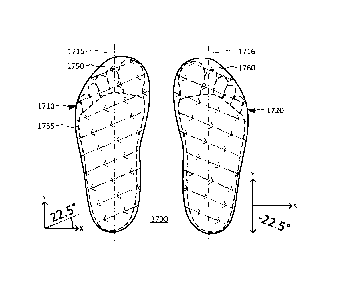
position. The postural platform includes a bottom surface defining a reference
plane, a top surface
configured as a contact surface for a foot of the user, and a perimeter side
wall between the bottom
and top surfaces. The top surface is rotated about a first rotational axis
parallel to the reference
plane and is rotated about a second rotational axis orthogonal to the
reference plane. When the
foot of the user is in contact with the top surface of the postural platform,
a first point of contact
on the top surface corresponding to an inside of a ball of the foot is higher
with respect to the
reference plane than a second point of contact corresponding with an inside of
a heel of the foot,
the second point of contact being higher with respect to the reference plane
than a third point of
contact corresponding with an outside of the ball of the foot, the third point
of contact being higher
with respect to the reference plane than a fourth point of contact
corresponding with an outside of
the heel of the foot.
[0010] In one embodiment of this aspect, the top surface substantially
conforms to the
shape of the foot of the user. In another embodiment, the top surface is
substantially planar.
-2-
Date Recue/Date Received 2024-01-05
100111 In one embodiment of this aspect, the top surface is rotated
between 100 and 12.5
about the first rotational axis and top surface is rotated between 20 and 25
about the second
rotational axis.
[0012] In another embodiment, the top surface has an outer periphery
shaped to
substantially match an outer periphery of a foot of a user.
[0013] In yet another embodiment, the top surface includes visual
indicia defining how a
foot of a user is to be oriented relative to the top surface when the foot of
the user is in contact
with the top surface.
[0014] In still yet another embodiment, the postural platform further
includes a pivot
member coupled to the bottom surface of the postural platform. The pivot
member allows the top
surface to rotate about the second rotational axis. The pivot member has a top
plate that is fixedly
coupled to the bottom surface of the performance platform and a bottom plate
that rotates with
respect to the top plate along the second rotational axis.
[0015] In another aspect, a postural platform to redistribute weight of
a user in a standing
position includes a bottom surface defining a reference plane, a top surface
configured as a contact
surface for a foot of the user, the top surface having a complex angle with
respect to the bottom
surface such that when the foot of the user is in contact with the top
surface, a first point of contact
on the top surface corresponding to an inside of a ball of the foot is higher
with respect to the
reference plane than a second point of contact corresponding with an inside of
a heel of the foot,
the second point of contact being higher with respect to the reference plane
than a third point of
contact corresponding with an outside of the ball of the foot, the third point
of contact being higher
with respect to the reference plane than a fourth point of contact
corresponding with an outside of
the heel of the foot, a perimeter side wall between the bottom and top
surfaces, and a covering
coupled to at least a portion of a perimeter of the top surface for forming at
least a partial housing
for the foot of the user located between the top surface and covering.
[0016] In one embodiment of this aspect, the top surface is
substantially planar. In another
embodiment, the top surface substantially conforms to a natural shape of the
foot of the user.
[0017] In one embodiment, the complex angle between the top and bottom
surfaces is
defined by the top surface is rotated between 10 and 12.5 about a first
rotational axis
-3-
Date Recue/Date Received 2024-01-05
parallel to the reference plane and rotated between 200 and 25 about the
second rotational axis
orthogonal to the reference plane.
[0018] In another embodiment of this aspect, the top surface includes
visual indicia
defining how the foot of the user is to be oriented relative to the top
surface when the foot of the
user is in contact with the top surface.
[0019] In yet another embodiment of this aspect, the postural platform
further includes a
pivot member coupled to the bottom surface of the postural platform, the pivot
member configured
to allow the foot contact surface to rotate about a second rotational axis
orthogonal to the reference
plane. The pivot member has a top plate that is fixedly coupled to the bottom
surface of the
postural platform and a bottom plate that rotates with respect to the top
plate along the second
rotational axis.
[0020] In another aspect, a postural platform system designed to
redistribute weight of a
user in a standing position includes a left foot platform having a bottom
surface defining a
reference plane, a top surface configured to support a left foot of the user,
the top surface being
rotated downwardly in a first direction about a first rotational axis parallel
to the reference plane
and rotated counter-clockwise about a second rotational axis orthogonal to the
reference plane, and
a right foot platform having a bottom surface defining a reference plane, a
top surface configured
to support a right foot of the user, the top surface being rotated downwardly
in a second direction
opposite the first direction about the first rotational axis parallel to the
reference plane and rotated
clockwise about the second rotational axis orthogonal to the reference plane.
[0021] In one embodiment, each of the left foot and right foot platforms
have a covering
coupled to at least a portion of a perimeter of the respective top surfaces of
each of the platforms
for fonning at least a partial housing for the respective left and right feet
of the user when located
between the respective top surfaces and coverings.
BRIEF DESCRIPTION OF THE DRAWINGS
[0022] Figure 1 is an axonometric perspective view of an example device
in accordance with
the technology disclosed herein.
[0023] Figure 2 is a top-down view, and a side view of the left portion,
showing certain
angles associated with the example device shown in Figure 1.
[0024] Figure 3 is a side view of the example device shown in Figure 1.
-4-
Date Recue/Date Received 2024-01-05
[0025] Figure 4 is a top-down view, and a side view of the right
portion, showing certain
angles associated with the example device shown in Figure 1.
[0026] Figure 5 is a side view of the example device shown in Figure 1.
[0027] Figure 6 is an axonometic perspective view of the example device
shown in Figure
1.
[0028] Figure 7 is a top-down oblique front view of the example device
shown in Figure
1.
[0029] Figure 8 is a front view of the example device shown in Figure 1.
[0030] Figure 9 is a back view of the example device shown in Figure 1.
[0031] Figure 10 is a top-down view of the example device shown in
Figure 1.
[0032] Figure 11 is a top-down view showing certain features of the left
portion of the
example device shown in Figure 1.
[0033] Figure 12 is a perspective view of reference planes in accordance
with the
technology disclosed herein.
[0034] Figure 13 is a front view of the reference planes shown in Figure
12.
[0035] Figure 14 is a top-down view of the reference planes shown in
Figure 12.
[0036] Figure 15 is a top-down view of an example device in accordance
with the
technology disclosed herein.
[0037] Figure 16 is a top-down view of another arrangement of the
example device shown
in Figure 15.
[0038] Figure 17 is a top-down view of the top surface of the sole of a
shoe in in accordance
the technology disclosed herein.
[0039] Figure 18 is a perspective view of the bottom surface of the
housing or an example
device in accordance with the technology disclosed herein.
[0040] Figure 19 is a top-down view showing four different locations of
contact of a foot
of a user on an example device.
[0041] Figure 20A is a top-down view showing an orientation of each of
the bones of an
exemplary right foot and ankle of a user superimposed on an outline of the
bones of a right foot
with respect to an example device.
-5-
Date Recue/Date Received 2024-01-05
[0042] Figure 20B is a top-down view of Figure 20A without the talus
bone of the
exemplary right foot and ankle being present.
[0043] Figure 20C is a top-down view of Figure 20A showing the fourth
and fifth
metatarsals and cuboid without the first, second, third metatarsals and
respective medial,
intermediate and lateral cuneiforms being present.
[0044] Figure 21A is a top-down view showing exemplary right foot and
ankle bones with
respect to an example device and a pivot point intermediate the fourth and
fifth metatarsals.
[0045] Figure 21B is a top down view of figure 21A superimposed on
another view of
figure 21A and rotated clockwise about the pivot point.
[0046] Figure 22 an exemplary bearing system that is configured to
contact a bottom
surface of an example device such that the example device can rotate about the
respective pivot
points shown in figures 21A and 21B.
[0047] Figure 23A is a perspective view of an example device for a left
foot showing a
pivot location on the top surface thereof.
[0048] Figure 23B is a front view of the example device of figure 23A.
[0049] Figure 23C is a rear view of the example device of figure 23A.
[0050] Figure 23D is a right side view of the example device of figure
23A.
[0051] Figure 23E is a left side view of the example device of figure
23A.
DETAILED DESCRIPTION
[0052] A training device is disclosed that disposes one or more portions
of a person's body
at particular angles when a person stands on or is otherwise supported by the
device. By way of
example, as shown in Figures 1-5, the device may have include a left portion
with a top surface
for contacting the left foot that is rotated substantially 22.5 counter-
clockwise and tilted
substantially 11.25 downward to the left relative to the forward direction of
the device and a right
portion with a top surface for contacting the right foot that is rotated
substantially 22.5 clockwise
and tilted substantially 11.25 downward to the right relative to the forward
direction. Figures 6-
9 provide other views of the device.
[0053] The device may also include indicia instructing how a user may
orient his or her
body relative to the device. For instance and as shown in Figure 10-11, the
device may include
visual indicia that suggests where a person should place one or more of his or
her feet on the
-6-
Date Recue/Date Received 2024-01-05
device. Figures 12-14 describe how the indicia may be determined based on the
angles of three
reference planes associated with, respectively, the bottom surface of the
device (which may rest
upon the ground surface), the top surface of the device (e.g., the surface
upon which a user may
rest his or her feet) and how the user may align his or her foot on the top
surface.
[0054] Figures 15-18 illustrate other examples of the technology
disclosed herein. By way
of example, Figures 15 and 16 illustrate an example wherein the left and right
portions are
detachably connected to one another at a hinge. Figure 17 illustrates how a
pair of shoes may use
the technology and Figure 18 illustrates how the bottom surface of the device
may be arranged.
[0055] For ease of reference and understanding, certain elements of the
technology
disclosed herein may be described relative to a three-dimensional Cartesian
coordinate system. In
that regard, and as shown by way of example by reference axes 105 in Figure 1,
the three-
dimensional coordinate system includes an x-axis, a y-axis orthogonal to the x-
axis and
intersecting the x-axis at an origin point, and a z-axis that intersects the
origin point and is
orthogonal to both the x-axis and the z-axis. The x-y plane is defined by the
plane containing both
the x-axis and the y-axis, the y-z plane is defined by the plane containing
both the y-axis and z-
axis, and x-z plane is defined by the plane containing both the x-axis and the
z-axis. Solely for
ease of reference, various examples below assume that the z-axis corresponds
with the direction
of gravity and the x-y plane generally corresponds with the ground plane,
e.g., the plane that is
orthogonal to the direction of gravity at the geographic location at which the
device is used.
However, except where expressly indicated, references herein to an element
extending in one
direction does not preclude the possibility that the element extends at least
in some part in another
direction as well.
[0056] Device 100 shown in Figure 1 provides one example of a device in
accordance with
the technology described herein. The conical arrows of lines of sight 3, 5 and
8 correspond with
the views shown in Figures 3, 5 and 8 respectively. The lines of sight in
Figure 1 and other figures
are shown for reference purposes only.
[0057] The device may include a housing with a top surface and bottom
surface. For
instance, the housing of device 100 may form a left portion 110 and a right
portion 120. Left
portion 110 includes left top surface 150 and right portion 120 includes right
top surface 160.
While left top surface 150, right top surface 160 and the bottom surface (not
shown in Figure 1)
-7-
Date Recue/Date Received 2024-01-05
of the specific example shown in Figure 1 may feel flat when used by a user,
the top and bottom
surfaces in accordance with other aspects of the technology described herein
may not be. Left top
surface 150 and right top surface 160 also include left visual indicia 115 and
right visual indicia
125, respectively, which are used to help a user align his or her feet when
standing on the device.
[0058] For further ease of reference, a device in accordance with the
technology disclosed
herein may be associated with a forward direction. For instance, device 100
may be associated
with a longitudinal axis 140 that stretches in a forward direction from point
141 near the front of
device 100 to a point near the back of the device (not shown). For ease of
reference, longitudinal
axis 140 of device 100 shall be considered parallel to the y-axis of reference
axes 105. For further
ease of reference, the forward direction may be considered to correspond with
the forward
direction of the human body.
[0059] As shown in Figures 2-5, the device may have a left top surface
and a right top
surface that are generally disposed at different angles with respect to each
other. For example, left
top surface 150 and right top surface 160 of the device may be tilted and
rotated relative to each
other. By further way of example, the orientation of the left top and right
top surfaces may be
described with respect to longitudinal axis 140. Figures 2 and 4 both show a
top-down view of
device 100. Figure 2 also shows a front/side view of left portion 110 from the
perspective of line
of sight 3 as if right portion 120 was removed from device 100, and that same
front/side view is
reproduced in Figure 3. Figure 4 is similar to Figure 2 in that it shows a top-
down view of device
100, but it also shows a front/side view of right portion 120 from the
perspective of line of sight 5
as if left portion 110 was removed from device 100. The same front/side view
in Figure 4 is
reproduced in Figure 5.
[0060] The bottom surface of the device may be substantially flat. For
example and as
shown in particular Figures 3 and 5, the bottom surface 790 of left portion
110 may be flat and
parallel to the x-y plane.
[0061] The top surface of the left portion may be tilted downward
relative to the center of
the device. For example, the dotted arrows in Figure 2 and other figures
indicate the downward
tilt direction of the top surface of the device. In that regard, and as shown
by axes 205 and axes
305 in Figures 2 and 3, respectively, left top surface 150 may be tilted
downward and to the left
relative to longitudinal axis 140. The tilt may be such that the acute angle
between the plane
-8-
Date Recue/Date Received 2024-01-05
defined by left top surface 150 and the plane generally defined by bottom
surface 790 (e.g., the x-
y plane generally corresponding with the ground plane) is substantially 11.25
(e.g., 11 to 11.5 )
and the left side of left top surface 150 (e.g., near left side edge 755) is
lower than the right side of
left top surface 150 (e.g., near top center edge 750).
[0062] The tilted top surface may also be rotated relative to the center
of the device, e.g.,
rotated in a direction parallel to the bottom surface and a certain number of
degrees relative to the
device's longitudinal axis. In that regard and as shown relative to axes 205
in Figure 2, the tilt
direction of left top surface 150 is substantially 67.5 counter-clockwise
(e.g., 67 to 68 ) relative
to longitudinal axis 140 in the x-y plane. In other words, the tilt direction
of left top surface 150
is rotated substantially 22.5 counter-clockwise compared to what the tilt
direction would have
been if it was tilted perpendicular to and away from longitudinal axis 140.
[0063] The right top surface may be tilted and rotated in opposite
directions to the left top
surface. For instance and as shown in Figures 4 and 5, right top surface 160
of right portion 120
may be rotated clockwise and tilted downward to the right relative to
longitudinal axis 140. By
way of example and as shown by axes 405 and axes 505: the acute angle between
the plane defined
by right top surface 160 and the plane defined by bottom surface 790 may be
substantially 11.25 ,
the right side of right top surface 150 (e.g., near right side edge 555) may
be lower than the left
side of right top surface 160 (e.g., near top center edge 750); and the tilt
direction of right top
surface 160 may be rotated substantially -22.5 (e.g., clockwise) compared to
what the tilt direction
would have been if it was tilted perpendicular to and away from longitudinal
axis 140. In that
regard the direction of tile of right portion 120 may be turned 45 relative
to the angle of tilt of the
first portion.
[0064] Figures 6-9 provide additional views of device 100. Figure 6
provides the same
perspective view of device 100 as of Figure 1. However, unlike Figure 1,
Figure 6 shades left top
surface 150 and right top surface 160, includes dashed lines indicating the
presence of hidden
edges, and omits left visual indicia 115 and right visual indicia 125. Figure
6 also includes lines
of sight 7 and 9, which correspond with the views shown in Figures 7 and 9,
respectively. Figure
7 is a top-down oblique view of device 100, Figure 8 is a front view of device
100, and Figure 9
is a back view of device 100.
-9-
Date Recue/Date Received 2024-01-05
[0065] A device in accordance with the technology disclosed herein may
provide indicia
for indicating a suggested alignment of a person's body during use. In that
regard, device 100 may
include indicia indicating how a user should orient his or her feet when
standing upon, squatting
upon, or is otherwise supported by the device. For instance, left portion 110
may include left
visual indicia 115 and right portion 120 may include right visual indicia 125.
By way of example,
left visual indicia 115 may be a line that is painted on left top surface 150,
that is centered between
left outer edge 754 and top center edge 750, and that extends in the forward
direction, parallel to
longitudinal axis 140. Similarly, right visual indicia 125 may be a line that
is painted on right top
surface 160, is centered between top center edge 750 and right edge 555, and
extends in the forward
direction, parallel to longitudinal axis 140.
[0066] The suggested alignment of a user's feet includes resting each
foot on the top
surface of the device so each foot points in the forward direction. A user may
similarly place the
second innermost toe and center of the heel of the user's right foot above
right visual indicia 125.
In that regard and as shown in Figure 10, a user may place his or her left
foot 1050 on left top
surface 150 such that both the second innermost toe 1052 (the toe next to the
big toe) and the center
of his or her heel 1054 is directly above left foot indicia 115. The visual
indicia may also be
arranged to enable a user to locate his or her foot in the recommended
alignment by aligning the
inside heel region of his or her foot slightly wider than the inside ball of
the foot region of his or
her foot.
[0067] The feet indicia may include other mechanisms for indicating a
suggested
alignment of the feet. For instance, instead of being a painted line, the feet
indicia may be a
groove embedded in the top of the surface, a footprint embedded in the surface
(e.g., similar to the
footprint shown in dashed lines in Figure 10), or any other visual indicia. In
addition to or instead
of visual indicia, the indicia may comprise other modes of placement detection
and feedback that
are capable of being perceived by a typical user. By way of example, left top
surface 150 and right
top surface 160 may include a grid of touch-sensitive sensors and device 100
may include a
processor that is configured to receive signals from the touch-sensitive
sensors and determine
whether the placement of the user's feet on the top surface is consistent with
the suggested
alignment. The device may also provide one or more of visual, audible or
tactile feedback signals
via an output component in communication with the processor (e.g., an LED
light, speaker or
-10-
Date Recue/Date Received 2024-01-05
haptic actuator) to indicate consistency with the suggested alignment (e.g.,
getting brighter, getting
louder or increasing vibration as the alignment becomes more consistent).
[0068] When a user's foot is placed on the device in accordance with the
suggested alignment,
it may not be level nor orthogonal relative to the ground plane. For example
and as show in Figure 11,
footprint 1150 outlines where a user's foot may contact left top surface 150
if a user's left foot was
placed on the surface and centered in the forward direction as indicated by
reference line 1115 (which
may be, in at least some aspects, parallel to longitudinal axis 140). If left
top surface 150 was generally
planar and substantially level relative to the ground plane, the points of
contact between the foot and
left top surface 150 would be substantially level as well. However, since left
top surface 150 itself is
both tilted substantially 11.25 downward to the left and rotated
substantially 22.5 counter-clockwise
(relative to the ground plane), different points of contact would not be level
with to each other or with
respect to gravity when a user is standing on the device. Rather, as indicated
by elevation reference
lines 1101-04, point of contact 1111 (which corresponds with the inside of the
ball of the foot) will be
higher than point of contact 1112 (corresponding with the inside of the heel),
which in turn will be
higher than point of contact 1113 (corresponding with the outside of the ball
of the foot), which in turn
will be higher than point of contact 1114 (corresponding with the outside of
the heel).
[0069] Figures 12-14 provide another illustration of the varying height
of a single foot that is
aligned with the top surface of the device as suggested above. All of the
figures provide a perspective
view of three rectangular reference planes, namely ground plane 1210, top
surface plane 1220 and
alignment plane 1230, relative to the three-dimensional Cartesian coordinate
system represented by
axes 1205. The perspective shown in the figure is subject to foreshortening,
i.e., the greater the distance
from the point of the view of the observer, the smaller the relevant element
will appear in the figures.
Ground plane 1210 may be a plane that is orthogonal to the direction of
gravity.
[0070] Top surface plane 1220 may be a plane upon which a user's foot
effectively rests when
the user is using the device. As shown in Figure 13, the device may be
configured and arranged to
orient top surface plane 1220 at a first angle 1260 relative to ground plane
1210. The first angle may
fall within a first range of angle values. By way of example, the first range
of values may be 11.25
plus or minus 0.25 such that first range may from 11 to 11.5 . In another
example, the first range of
values may be 11.25 plus or minus 1.25 such that first range may be from 10
to 12.5 . In yet another
example, the first range of values may be 11.25 plus or minus 3.25 such that
the range may be from
8 to 14.5 .
-11-
Date Regue/Date Received 2024-01-05
[0071] If the device is expected to be used on a flat, level floor
(e.g., a floor that is that is
substantially orthogonal to direction of gravity), the top and bottom surfaces
of the device's housing
may be substantially planar and fixed at an angle relative to each other in a
manner similar to that
described above in connection with device 100. However, other devices in
accordance with the
technology disclosed herein may be configured for use on surfaces that are not
flat or level. For
instance, the housing of another device in accordance with the technology
disclosed herein may include
a bottom portion that includes three or more legs that can be telescoped and
moved to rest on an uneven
floor or other ground surface. The top portion of such a device may have a
substantially planar surface,
e.g., it may be planar with respect to the points at which the foot contacts
the top surface such that the
device substantially establishes the plantar plane of the foot defined by its
skeletal structure relative to
direction of gravity. The top portion may be moveable relative to the bottom
portion's points of
contact with the ground surface. By way of example, such a device may have a
middle portion disposed
between the top and bottom portion that includes a gimbal for automatically
stabilizing the top surface
of the device, and thus the plane of the foot, relative to gravity even if the
ground surface at which the
device is used is uneven.
[0072] The intersection of the top surface plane and the ground plane
may be used to define
the relevant axes of a three-dimensional Cartesian coordinate system. For
example and as represented
by axes 1205, the x-y plane may be defined as being co-planar with the ground
plane, the y-axis may
be defined as being co-linear with the intersection line of top surface plane
1220 and ground plane
1210, and the y-z plane may be defined as a plane that is orthogonal to the
ground plane and contains
the intersection line of top surface plane 1220 and ground plane 1210. Figure
13 and shows the planes
from a line of sight co-linear with the x-y plane (ground plane 1210) and
parallel with the y-axis, and
Figure 13 shows the planes from a line of sight looking directly downward at
that plane, parallel with
the z-axis.
[0073] Alignment plane 1230 may be a plane that is used to deteunine the
suggested alignment
of a person's foot relative to the ground plane. The alignment plane may be
defined as a plane that is
orthogonal to the ground plane and disposed at an angle relative to another
reference plane that is
orthogonal to the ground plane but contains the intersection of top surface
plane with the ground plane.
For example, such a reference plane may be y-z plane shown in Figures 12-14.
In that regard and as
shown in Figure 14, alignment plane 1230 may be disposed at a second angle
1270 relative to the y-z
plane. The second angle may fall within a second range of angle values. By way
of example, the
-12-
Date Regue/Date Received 2024-01-05
second range of values may be 22.5 plus or minus 0.5 such that the second
range may be from 22
to 23 . In another example, the second range of values may be 22.5 plus or
minus 2.5 such that the
second range may be from 20 to 25 . In another example, the second range of
values may be 22.5
plus or minus 5 such that the range of values may be between 17.5 and 27.5 .
[0074] Alignment line 1250, which is shown Figures 12-14 as a dark thck
line, is defined as
the line at which alignment plane 1230 intersects top surface plane 1220. When
the first angle is within
the first range and the second angle is within the second range, alignment
line 1250 will be disposed
at an angle relative to the ground plane. To help illustrate this effect,
Figure 12 includes elevation
lines 1235 (dotted lines) that are contained in alignment plane 1230 and
parallel to ground plane 1210.
[0075] Alignment line 1250 may be used to align a user's foot relative
to the top surface. For
the purposes of this disclosure, the longitudinal axis of a person's foot is
considered to be the center
line of the foot. When a user rests a foot on the top surface of the device
such that the longitudinal
axis of the user's foot is parallel to alignment line (e.g., directly above
and parallel to alignment line
1250), the alignment of a user's foot may be similar to the suggested
alignment described above in
connection with Figure 11.
[0076] During operation, a user may perform, on the device, many of the
same exercises that
are traditionally perfoimed on the floor. By way of example, when operating
device 100, a user may
use the device by placing his or her left foot on left top surface 150 and
right top surface 160, with his
or her feet facing in the forward direction, and then perform exercises such
as squats (with or without
weights), kettlebell swings and lifts, dead lifts, overhead pressing, swinging
clubs and ropes,
plyometric jumps and physical practices such as standing meditation and
standing breathing exercises.
[0077] Although the technology is not limited to particular dimensions
or shapes, the outer
shape of the device shown in Figures 1-9 is considered advantageous because,
among other reasons,
it also functions as visual indicia of the suggested alignment. For example,
when viewed from the top
down by a user standing on the device, top center edge 750 and left outer edge
754 are parallel to the
direction of the left foot when it is in the suggested alignment, and top edge
752 and top edge 756 are
perpendicular to that alignment. The other top edges, namely top edges 751,
753, 755 and 757,
correspond with the substantially 22.5 rotation and may help a user get a
better understanding of the
direction of the tilt of the left and right portions when getting on or off
the device.
-13-
Date Regue/Date Received 2024-01-05
[0078] By way of further example, the following edges shown in Figures 6-
9 and their
corresponding edges on right portion 120 may have the following approximate
lengths when device
100 is sized for use by adults:
top edge 750 332 mm
top edge 751 216 mm
top edge 752 169 mm
top edge 753 220 mm
top edge 754 230 mm
top edge 755 324 mm
top edge 756 130 mm
top edge 757 216 mm
side edge 760 132 mm
side edge 761 132 mm
side edge 762 93 mm
side edge 763 40 mm
side edge 764 18 mm
side edge 765 18 mm
side edge 766 47 mm
side edge 767 100 mm
bottom edge 770 330 mm
bottom edge 771 216 mm
bottom edge 772 165 mm
bottom edge 773 213 mm
bottom edge 774 229 mm
bottom edge 775 324 mm
bottom edge 776 127 mm
bottom edge 777 209 mm
[0079] By way of another example, the following edges shown in Figures 6-
9 and their
corresponding edges on right portion 120 may have the following approximate
lengths when device
100 is sized for use by adults:
top edge 750 331 mm
top edge 751 216 mm
top edge 752 168 mm
top edge 753 217 mm
top edge 754 229 mm
top edge 755 324 mm
top edge 756 129 mm
top edge 757 214 mm
side edge 760 108 mm
side edge 761 108 mm
side edge 762 78 mm
side edge 763 35 mm
side edge 764 18 mm
-14-
Date Regue/Date Received 2024-01-05
side edge 765 18 mm
side edge 766 41 mm
side edge 767 83 mm
bottom edge 770 331 mm
bottom edge 771 216 mm
bottom edge 772 168 mm
bottom edge 773 217 mm
bottom edge 774 228 mm
bottom edge 775 324 mm
bottom edge 776 127 mm
bottom edge 777 209 mm
[0080] As shown in Figure 8, the height 810 of device 100 may be 132 mm,
the width 820
of device 100 may be 444.50 mm, and the length of device in the y-direction
(not shown) may be
609.60 mm.
[0081] The device may be composed of various materials. By way of
example, the housing
of device 100 may be manufactured via rotational molding using plastic
polymers or constructed
of wood, high density foam, cork, metal or combinations of the foregoing.
[0082] The top surface may be composed of a different material than the
remainder of the
device. For instance, in order to mitigate the likelihood of a user slipping
on the device, left top
surface 150 and right top surface 160 may each have a sturdy lower layer and a
resilient upper
layer of a material with a high coefficient of friction, such as rubber. The
upper layer of the top
surface of the device may also be texturized with knurls or similar
protrusions to further mitigate
the likelihood of slipping. Visual indicia 115 and 125 may be constructed of
foam, rubberized
material, grip tape, paint, decals or combinations of the foregoing.
[0083] The device may be configured so that the left portion and right
portions can be
moved with respect to each other. For example, Figure 15 shows a device 1500
that is similar to
the device 100. However, device 1500 includes a hinge 1580 that connects left
portion 1510 to
right portion 1516 and permits the two portions to be rotated towards or away
from each other
parallel to the ground plane. The device may also include indici a for
indicating the relative rotation
of the tilt. By way of further example, device 1500 may include angle
indicator 1590, and left
portion 1510 may include a plurality of lines that are labeled with angle
numbers and meet at hinge
1580. Right portion 1516 may include a similar plurality of lines that mirrors
the angle indicator
on left portion 1510. The approximate angle of tilt relative to the forward
direction of the device
-15-
Date Recue/Date Received 2024-01-05
may correspond with the two lines of the angle indicator that line up the most
closely with each
other. In the example shown in Figure 15, the two lines labelled "45 " are
relatively co-linear
with each and, as shown by axes 1501 and 1502, the angle of tilt of left top
surface 1550 and right
top surface 1560 with respect to longitudinal axis 1540 is 45 and -45
respectively. Other angle
indicia may also be used. For instance, instead of indicating the relative
angle of tilt relative to
the device's longitudinal axis, the angle indicator may indicate other angles
such as the angle
between the direction of left foot indicia 1515 and right visual indicia 1525.
[0084] The device may also be configured to permit the left and right
portion to be
detached from each other. For example and as shown in Figure 16, hinge 1580
may also permit
left portion 1510 to be detached from right portion 1516, in which case a user
may space the
portions further from one another and use device 1500 as previously described
in connection with
device 100.
[0085] Another example of the left and right portion being separated
from each other is
shown in Figure 17, which illustrates top-down view of a pair of shoes 1700 in
accordance with
the technology disclosed herein. The left portion is associated with left shoe
1710 and the right
portion is associated with right shoe 1720. In that regard, left top surface
1750 of the sole of left
shoe 1710 may be tilted substantially 11.25 downward to the left and rotated
substantially 22.5
counter-clockwise and right top surface 1760 of the sole of right shoe 1720
may be tilted
substantially 11.25 downward to the right and rotated substantially 22.5
clockwise. The indicia
for the proper foot alignment may be omitted from pair of shoes 1700 since a
properly-fitted shoe
may automatically align the left foot's longitudinal axis 1715 and right
foot's longitudinal axis
1716 relative to the direction of tilt and rotation.
[0086] The top surfaces of the soles of the pair of shoes shown in
Figure 15, as well as the
top surface of other devices in accordance with the technology disclosed
herein, may be non-
planar. For instance, left top surface 1550 of left shoe 1710 and right top
surface 1760 of right
shoe 1720 may include cushioned arches that extend upwards relative to the
rest of the sole to
provide additional comfort or support to the user's foot. Yet further, even if
the portion of the top
surface upon which a user stands is planar, the remainder of the top surface
the top surface of
device 100 may be curved. For example, while top center edge 750 of device 100
is shown in
Figure 1 as a linear edge, the center of device 100, left top surface 150 and
right top surface 160
may collectively form a smooth single surface that gently curves and
transitions from the tilt and
-16-
Date Recue/Date Received 2024-01-05
rotation of left portion 110 to the tilt and rotation of right portion 120. In
that regard, the
topography of the top surface(s) of the device may be non-planar, provided the
surface(s) align the
left foot, the right foot or both within the disclosed angle range.
[0087] A device in accordance with the technology described herein may
include other
features as well. For instance, Figure 18 illustrates the bottom of a device
1800 with a shape
similar to that of device 100. Device 1800 includes handles 1880 and 1890 that
are integral with
left portion 1810 and right portion 1818, respectively. The bottom surface may
also include feet,
such as rubberized foot 1891, to help keep the device in place while being
used. For example and
as show in Figure 18, the bottom surface of left portion 1810 and the bottom
surface of right portion
1818 may each include four rubberized feet at opposite corners of each
portion.
[0088] Figure 19 is a top-down view showing four different locations of
contact of a foot
of a user on an example device or postural platform 1900. A top surface 1960
is oriented at a
complex angle with respect to bottom surface 1990. Top surface 1960 is tilted
or rotated about a
first rotational axis Al parallel to a bottom surface 1990 between 8 and 14.5
. In the present
example, top surface is rotated about the first rotational axis 11.25 . Given
that device 1900 in the
present example is a right postural platform, top surface 1960 is titled
downward to the right. Top
surface 1960 is also rotated or turned clockwise about a second rotational
axis A2 perpendicular
to the bottom surface 1990 between 17.5 and 27.5 . In the present example,
top surface is rotated
about the second rotational axis 22.5 . A perimeter side wall 1970 is located
between top surface
1960 and bottom surface 1990. While the top portion of figure 19 is shown in a
top view the
bottom portion of figure 19 is a side view rotated 90 from the top view.
These top and side views
together provide perspective as to where the foot of a user is preferably
located on the top surface
of the present postural platform.
[0089] When a user places his or her right foot on top surface 1960 of
postural platform
1900, different points of contact of the foot are no longer level with respect
to each other. For
example, a first point of contact 1901 corresponding to the inside of the ball
of the foot adjacent
the first metatarsal will be higher with respect to the ground or reference
plane in a linear direction
perpendicular to the reference plane than a second point of contact 1902
corresponding with the
inside of the heel, which in turn will be higher than a third point of contact
1903 corresponding
with the outside of the ball of the foot, which in turn will be higher than a
fourth point of contact
1904 corresponding with the outside of the heel.
-17-
Date Recue/Date Received 2024-01-05
[0090] Figure 20A shows an orientation of each of the bones of an
exemplary right foot
and ankle with respect to a postural platform 2000 having a planar top surface
2060 and a planar
bottom surface 2090. In this aspect, the top surface 2060 is shown having an
alternative periphery
2062 that surrounds the bones of the right foot. In this aspect, the perimeter
of a right shoe is
shown in a similar manner to the right shoe shown in figure 17. In the present
figure, however,
the right shoe is superimposed on a larger square shaped depiction of a top
surface 2060 in order
to show the orientation of the top surface 2060 with respect to the bottom
surface 2090 in more
detail.
[0091] Bottom surface 2090 defines a first longitudinal axis Al which is
parallel to bottom
surface 2090 and is parallel to the y-axis. Top surface 2060 or top surface
periphery 2062 is rotated
about longitudinal axis Al or tilted downwardly to the right substantially
11.25 . In other
embodiments, top surface 2060 or top surface periphery 2062 may be rotated
about longitudinal
axis Al or tilted downwardly to the right more or less than 11.25 . Bottom
surface 2090 further
defines a second longitudinal axis A2 parallel to the z-axis and perpendicular
to the first
longitudinal axis Al. Top surface 2060 or top surface periphery 2062 is
rotated about second
longitudinal axis A2 or turned clockwise with respect to the second
longitudinal axis 22.5 . In
other embodiments, top surface 2060 or top surface periphery 2062 may be
rotated about second
longitudinal axis or turned clockwise with respect to the second longitudinal
axis A2 more or less
than 22.5 . The direction of the arrows in this figure depicts the orientation
of top surface 2060
and top surface periphery 2062 with respect to bottom surface 2090 angled in
both the y and z
axes.
[0092] When a person is in an upright standing position, the natural
weight bearing forces
are toward the inside or medial portion of the body. For each foot, the weight
of the body is
generally distributed to the big toe toward the inside of the body. The top
surface 2060 or top
surface periphery 2062 of postural platform 2000 is oriented to transfer the
weight laterally or to
the outside where the skeleton is more substantial.
[0093] Figure 20B shows the talus bone being removed. The talus lies
posteriorly between
the lower limb bones above, the calcaneum below and the other tarsal bones in
front. It has no
muscle attachments but is important for transmitting the body weight from the
tibia down to the
calcaneum and forwards to the navicular and other tarsal bones. It therefore
is a floating bone that
acts as a wedge between the tibia to bones of the foot. The talus has thee
articulating facets with
-18-
Date Recue/Date Received 2024-01-05
the calcaneus, delineated as the anterior, middle and posterior facets. These
facets distribute
weight in such a manner that can lead to the collapse of the bones of the foot
or rotation of the foot
bones medially or toward the inside of the body. A benefit of using a
performance or postural
platform for standing, walking and/or training, is shifting this normal weight
distribution laterally
in turn leading to greater balance, performance and strength of the ankle and
foot bones as well as
reducing the potential wear and tear on these bones.
[0094] Figure 20C shows the fourth and fifth metatarsals and cuboid
without the first,
second, third metatarsals and respective medial, intermediate and lateral
cuneiforms being present.
Here, body weight is distributed to the base of the skeleton which may be
referred to as the heel
bone and fourth and fifth metatarsals when standing on postural platform 2000.
The orientation
of top surface 2060 and top periphery surface 2062 of postural platform 2000
reorients the facets
of the talus with respect to the calcaneus and other bones of the feet, which
redistributes the body
weight of a user to the outside bones of the foot where the skeleton is
structurally strong.
[0095] Figure 21A shows exemplary right foot and ankle bones with
respect to a postural
platform 2100 in which a pivot location 2110 is depicted. The pivot location
2120 has a pivot axis
depicted by point 2125 located between the fourth and fifth metatarsal bones.
The arrows depict
rotation of postural platform in a clockwise direction about pivot point 2125.
An exemplary pivot
member 2200 when coupled to postural platform 2100 allows postural platform
2100 to pivot from
a neutral or first position as shown in figure 20A to an active or second
position as shown in figure
21B. While the arrows are only depicted in a clockwise direction, it should be
understood that the
rotational movement of a right postural platform 2100 from the neutral
position shown in figure
21A to a rotated clockwise position about pivot point 2125 shown in figure
21B, is limited by the
external rotation capabilities of a particular user. Pivot member 2200 allows
postural platform
2100 to then rotate counterclockwise back to the neutral position shown in
figure 21A. When
rotating back to the neutral position this is limited by the internal rotation
capabilities of the user.
Pivot member 2200 therefore allows a user to alternate between internal and
external rotational
movements of postural platform 2200 during strength training, for example. As
shown in figure
22, pivot member 2200 is an exemplary bearing system that is configured to
contact a bottom
surface of postural platform. Pivot member 2200 has a top plate 2230 that is
fixedly coupled to a
bottom surface of a postural platform and a bottom plate 2250 that rotates
with respect to top plate
2230 along the second rotational axis of postural platform. Top plate 2230 and
bottom plate 2250
-19-
Date Recue/Date Received 2024-01-05
may rotate with respect to each other via a plurality of rotatable ball
bearings 2240 housed in
between top plate 2230 and bottom plate 2250. The general concept of the
incorporation of a pivot
system to a postural platform is to allow a postural platform to rotate in
alternating clockwise and
counterclockwise directions in order to strengthen the muscles and joints, for
example, of the foot
and ankle to facilitate strength training and weight distribution of the body
laterally. In other
embodiments, any device that allows the postural platform to pivot during use
can be implemented.
Figures 23A-E show an example device or postural platform 2300 for a left
foot. Figure 23 is a
perspective view showing a pivot location 2320 on top surface 2360 if a pivot
member such as
pivot member 2200 shown in figure 22 was fixedly coupled to a bottom surface
2390 of platform
2300. Platform 2300 includes a perimeter side wall 2370 between top surface
2360 and bottom
surface 2390. In this embodiment top surface 2360 includes a periphery 2362
that has the general
shape of a left foot A covering (not shown) for housing the foot of a user in
contact with top
surface 2360 can be coupled to the entirety of periphery 2362 or adjacent the
entirety of periphery
2362. In other embodiments, a covering can be coupled to a portion of
periphery 2362 or adjacent
a portion of periphery 23262. As can be seen in each of figures 23A-E, the
height of perimeter
side wall 2370 varies about the perimeter of platform 2300. For example, the
height of perimeter
side wall 2370 in an anterior or front portion of platform 2370 as seen in
figure 23B in which the
toes of a user would be located is generally more than the height of perimeter
side wall 2370 in a
back portion of platform 2370 as seen in figure 23C in which the heal of the
user would be located.
The height of perimeter side wall 2370 in a medial or right portion of
platform 2370 as seen in
figure 23D generally decreases from an anterior or front of the foot where the
toes are located to a
posterior or rear of the foot where the heal is located. The height of
perimeter side wall 2370 in a
lateral or left portion of platform 2370 as seen in figure 23E generally
decreases from an anterior
or front of the foot where the toes are located to a posterior or rear of the
foot where the heal is
located.
[0096]
As shown for example in figure 23C, when a user places his or her left foot on
top
surface 2360 of postural platform 2300, different points of contact of the
foot are no longer level
with respect to each other. For example, a first point of contact 2301
corresponding to the inside
of the ball of the foot adjacent the first metatarsal will be higher with
respect to the ground or
reference plane in a linear direction perpendicular to the reference plane
than a second point of
contact 2302 corresponding with the inside of the heel, which in turn will be
higher than a third
-20-
Date Recue/Date Received 2024-01-05
point of contact 2303 corresponding with the outside of the ball of the foot,
which in turn will be
higher than a fourth point of contact 2304 corresponding with the outside of
the heel.
[0097] In the above embodiments, the example devices and postural
platforms are shown
with a planar top surface. In other embodiments, the top surface substantially
conforms to the
shape of the foot of the user when the foot of the user is in contact with the
top surface. In other
embodiments, the top surface has the general shape or contour of the foot of a
user without the
foot of a user being in contact with the top surface. The top surface may
conform to the contours
of a foot of a user in that it is not completely rigid. In these embodiments,
the top surface may
compress such that the portion of the top surface in contact with the foot of
the user takes the
general shape of the contours of the bottom surface of the user's foot. While
the top surface may
compress, this does not alter the relative orientation of the top surface as
defined by the first,
second, third and fourth contact points, for example. It is further
appreciated that postural
platforms may be an insert or wedge for insertion in a sandal, shoe, sneaker,
boot or any foot
covering or the general non-removable foot contact support within a sandal,
shoe, sneaker, boot or
any foot covering.
[0098] As these and other variations and combinations of the features
discussed above can
be utilized without departing from the invention as defined by the claims, the
foregoing description
of the embodiments should be taken by way of illustration rather than by way
of limitation of the
invention as defined by the claims. The provision of examples of the invention
(as well as clauses
phrased as "such as," "e.g.", "including" and the like) should not be
interpreted as limiting the
invention to the specific examples; rather, the examples are intended to
illustrate only some of
many possible aspects. Similarly, references to "based on" and the like means
"based at least in
part on".
-21-
Date Recue/Date Received 2024-01-05