Note: Descriptions are shown in the official language in which they were submitted.
WO 2021/026093
PCT/US2020/044790
SYSTEM AND METHOD FOR IMPROVING COLOR APPEARANCE
OF SOLAR ROOFS
CROSS-REFERENCE TO RELATED APPLICATION
[0001] This application claims priority to U.S. Patent Application No.
16/533,524
titled "SYSTEM AND METHOD FOR IMPROVING COLOR APPEARANCE OF SOLAR
ROOFS," filed August 6, 2019, the content of which is incorporated herein by
reference in
its entirety for all purposes.
FIELD
100021 This disclosure is generally related to photovoltaic (or "PV") roof
tiles. More
specifically, this disclosure is related to photovoltaic roof tiles that have
consistent and
isotropic color appearance.
BACKGROUND
Related Art
[0003] In residential and commercial solar energy installations, a building's
roof
typically is installed with photovoltaic (PV) modules, also called PV or solar
panels, that can
include a two-dimensional array (e.g., 6x12) of solar cells. A PV roof tile
(or solar roof tile)
can be a particular type of PV module offering weather protection for the home
and a
pleasing aesthetic appearance, while also functioning as a PV module to
convert solar energy
to electricity. The PV roof tile can be shaped like a conventional roof file
and can include
one or more solar cells encapsulated between a front cover and a back cover,
but typically
enclose fewer solar cells than a conventional solar panel.
[0004] The front and back covers can be fortified glass or other material that
can
protect the solar cells from weather elements. To ensure sufficient
transmission of sunlight,
the front cover needs to be transparent, whereas the encapsulated photovoltaic
structures are
often dark colored. When viewed from a shallow angle (e.g., when the roof is
viewed from
the street), the dark-colored photovoltaic structures can become visible. The
color contrast
between the photovoltaic structures and the glass cover can create a scene
that is not
aesthetically pleasing. Moreover, a solar roof typically includes a mixture of
PV roof files as
well as non-PV roof tiles, with the non-PV roof tiles installed at locations
that are less likely
1
CA 03144911 2022-1-19
WO 2021/026093
PCT/US2020/044790
to receive sufficient sunlight. Although the non-PV roof tiles can include
similar glass covers
as those of the PV roof tiles, the absence of embedded photovoltaic structures
can result in
the non-PV roof tiles having a different color appearance than that of the PV
roof tiles.
SUMMARY
[0005] One embodiment can provide a photovoltaic roof tile. The photovoltaic
roof
tile can include a transparent front cover, a transparent back cover, and a
plurality of
polycrystalline-Si-based photovoltaic structures positioned between the front
cover and the
back cover. A respective polycrystalline-Si-based photovoltaic structure has a
front surface
facing the front cover and a back surface facing the back cover. The
photovoltaic roof tile
can further include a paint layer positioned on a back surface of the back
cover facing away
from the front cover. A color of the paint layer can substantially match a
color of the front
surface of the respective polycrystalline-Si-based photovoltaic structure.
[0006] In a variation on this embodiment, the front surface of the respective
polycrystalline-Si-based photovoltaic structure is textured using a reactive
ion etching (RlE)
technique.
[0007] In a further variation, features of the textured front surface of the
respective
polycrystalline-Si-based photovoltaic structure have a dimension less than one
micron.
[0008] In a variation on this embodiment, a front surface of the transparent
front
cover is textured.
[0009] In a further variation, the textured front surface of the transparent
front cover
can include a first texture pattern superimposed on a second texture pattern,
and a feature size
of the first texture pattern is smaller than a feature size of the second
texture pattern.
[0010] In a variation on this embodiment, the paint layer can include a
polymer-based
paint.
[0011] One embodiment provides a system and method for fabricating a plurality
of
photovoltaic roof tiles. During operation, the system obtains a plurality of
photovoltaic
structures, with a respective photovoltaic structure comprising a front
surface and a back
surface. The system measures a color of the front surface of each photovoltaic
structure,
groups the photovoltaic structures into at least two groups based on the
measured color of the
front surface of each photovoltaic structure, and forms the plurality of
photovoltaic roof tiles
by sequentially selecting photovoltaic structures from the at least two groups
based on a
predetermined pattern. A respective photovoltaic roof tile can include at
least two
2
CA 03144911 2022-1-19
WO 2021/026093
PCT/US2020/044790
photovoltaic structures encapsulated between a front transparent cover and a
back transparent
cover.
[0012] One embodiment provides a system and method for forming a photovoltaic
roof comprising a plurality of photovoltaic roof tiles and a plurality of non-
photovoltaic roof
tiles. During operation, the system fabricates the plurality of photovoltaic
roof tiles and the
plurality of non-photovoltaic roof tiles. A respective photovoltaic roof tile
can include a
transparent front cover, a transparent back cover, and a plurality of
photovoltaic structures
encapsulated between the front and back covers. Fabricating the plurality of
photovoltaic
roof tiles can include measuring a color of a front surface of each
photovoltaic structure and
applying a paint layer on a back surface of the back cover, and a color of the
paint layer can
substantially match the measured color. A respective non-photovoltaic roof
tile can include a
glass substrate and a second paint layer positioned on a back surface of the
glass substrate.
The system then installs the photovoltaic roof tiles and the non-photovoltaic
roof tiles at
predetermined locations on a roof
BRIEF DESCRIPTION OF THE FIGURES
[0013] The patent or application file contains at least one drawing executed
in color.
Copies of this patent or patent application publication with color drawing(s)
will be provided
by the Office upon request and payment of the necessary fee.
[0014] FIG. 1 shows an exemplary configuration of photovoltaic (PV) roof tiles
on a
house.
[0015] FIG. 2 shows the top and cross-sectional views of an exemplary
photovoltaic
roof tile and an exemplary non-photovoltaic roof tile, according to an
embodiment.
[0016] FIG. 3 shows exemplary color distribution of PV roof tiles containing
polycrystalline-Si-based solar tiles, according to one embodiment.
[0017] FIG. 4 illustrates the comparison between a number of custom-designed
background colors and solar cell colors, according to one embodiment.
[0018] FIG. 5 shows the grouping of solar cells having different colors,
according to
one embodiment.
[0019] FIG. 6 demonstrates various cell-arrangement patterns, according to one
embodiment.
[0020] FIG. 7 shows the example of a roof having clustered cell colors.
[0021] FIG. 8A shows the color distribution on a solar roof for two different
solar cell
designs, according to one embodiment.
3
CA 03144911 2022-1-19
WO 2021/026093
PCT/US2020/044790
[0022] FIG. 8B presents a flowchart illustrating an exemplary process for
manufacturing a photovoltaic roof, according to an embodiment.
[0023] FIG. 9 shows the color histogram of PV and non-PV roof tiles, according
to
one embodiment.
[0024] FIG. 10 shows the surface of roof tiles resulting from different
surface etching
conditions, according to one embodiment.
[0025] FIG. 11 shows the average lightness of the tiles as a function of time
of day,
according to one embodiment.
[0026] FIG. 12 shows the front glass cover of a roof tile, according to one
embodiment.
[0027] FIG. 13 shows the color effect of the thin-film coating with various
thicknesses, according to one embodiment.
[0028] FIG. 14 shows a partial view of a roof having tiles with different thin-
film
coatings, according to one embodiment.
[0029] FIG. 15 shows the comparison between a smooth tile surface and a
textured
tile surface, according to one embodiment.
[0030] FIG. 16A shows various exemplary microtexture patterns on a glass
surface,
according to one embodiment.
[0031] FIG. 16B shows a partial view of a roof having tiles with different
texture
patterns, according to one embodiment.
[0032] FIGs. 17A-17B show exemplary scenarios of in-tile color contrast,
according
to one embodiment.
[0033] FIG. 18 shows a different scenario of in-tile color contrast, according
to one
embodiment.
[0034] FIG. 19 shows a number of exemplary microscopic texture patterns,
according
to one embodiment.
[0035] FIG. 20 shows an exemplary roof tile cover having a tree bark surface
texture,
according to one embodiment.
[0036] FIG. 21A shows a contour on a glass surface, according to one
embodiment.
[0037] FIG. 21B shows an exemplary textured glass surface, according to one
embodiment.
[0038] FIG. 22A presents an exemplary front glass cover, according to one
embodiment.
4
CA 03144911 2022-1-19
WO 2021/026093
PCT/US2020/044790
[0039] FIG. 22B presents an exemplary multilayer thin-film stack, according to
one
embodiment.
[0040] FIG. 23A shows the reflection spectrum of a multilayer thin-film stack
on a
glass substrate, according to one embodiment.
[0041] FIG. 23B shows the color appearance of the multilayer thin-film stack
under
different viewing angles, according to one embodiment.
[0042] FIG. 24A illustrates the side view of an exemplary solar panel,
according to
one embodiment.
[0043] FIG. 24B shows a partial view of the panel, according to one
embodiment.
[0044] FIG. 25A illustrates the top view of an exemplary front cover of a
solar panel,
according to one embodiment.
[0045] FIG. 25B illustrates the amplified side view of a step on the front
cover,
according to one embodiment.
[0046] FIG. 26A shows the top view of an exemplary solar panel front cover,
according to one embodiment.
[0047] FIG. 26B shows the perspective view of the solar panel front cover,
according
to one embodiment.
[0048] FIG. 27 shows multiple interlocking solar panels, according to one
embodiment.
[0049] In the figures, like reference numerals refer to the same figure
elements.
DETAILED DESCRIPTION
[0050] The following description is presented to enable any person skilled in
the art to
make and use the embodiments, and is provided in the context of a particular
application and
its requirements. Various modifications to the disclosed embodiments will be
readily
apparent to those skilled in the art, and the general principles defined
herein may be applied
to other embodiments and applications without departing from the spirit and
scope of the
present disclosure. Thus, the disclosed system is not limited to the
embodiments shown, but
is to be accorded the widest scope consistent with the principles and features
disclosed
herein.
Overview
[0051] Embodiments of the invention solve at least the technical problem of
improving aesthetics of solar roof tiles at a low cost. A solar roof tile (or
PV roof tile) can
CA 03144911 2022-1-19
WO 2021/026093
PCT/US2020/044790
include a number of solar cells sandwiched between a front glass cover and a
back cover.
Due to manufacturing imperfections, the solar cells, and hence, the PV roof
tiles, can have
inherent color variations. Moreover, PV roof tiles can also have different
color appearances
under different lighting and/or at different viewing angles. To mitigate the
color contrast,
either within a PV roof tile or between PV roof tiles and non-PV roof tiles,
in some
embodiments, a robust color-management scheme is adopted while manufacturing
the tiles.
First, to reduce the color contrast within a PV roof tile, the PV roof tile
can encapsulate
polycrystalline-Si-based photovoltaic structures. By controlling the size and
pattern of the
surface texture of the polycrystalline-Si-based photovoltaic structures, one
can reduce the
"glow" of the photovoltaic structures. While keeping the front cover of the
roof tile
transparent, the back surface of the back cover can be coated with a layer of
paint that
matches the color of the textured surface of the photovoltaic structures to
reduce the color
contrast within the PV roof tile. A similar paint layer can also be deposited
onto the back
surface of the non-PV roof tiles. As a result, the color appearance of the PV
and non-PV roof
tiles can be quite similar. Moreover, when assembling the PV roof tiles, the
embedded
photovoltaic structures are fed into the production line following a
predetermined color
pattern such that a majority of PV roof tiles contains solar cells of a
similar color and PV roof
tiles of different colors are evenly or randomly mixed to prevent clustering
of colors on a
roof
100521 In alternative embodiments, one can also create PV roof tiles as well
as non-
PV roof tiles having significantly different surface colors by selectively
treating the surface
of their front glass covers. There are different ways of treating the front
surface of the front
glass cover, such as surface texturing or coating. By randomly placing roof
tiles, either PV or
non-PV tiles, of different colors on the roof, one can distract a viewer from
noticing the color
difference between PV and non-PV tiles. The resulting roof is also more
aesthetically
pleasing.
100531 A "solar cell" or "cell" is a photovoltaic structure capable of
converting light
into electricity. A cell may have any size and any shape, and may be created
from a variety
of materials. For example, a solar cell may be a photovoltaic structure
fabricated on a silicon
wafer or one or more thin films on a substrate material (e.g., glass, plastic,
or any other
material capable of supporting the photovoltaic structure), or a combination
thereof.
100541 A "solar cell strip," "photovoltaic strip," "smaller cell," or "strip"
is a portion
or segment of a photovoltaic structure, such as a solar cell. A photovoltaic
structure may be
divided into a number of strips. A strip may have any shape and any size. The
width and
6
CA 03144911 2022-1-19
WO 2021/026093
PCT/US2020/044790
length of a strip may be the same or different from each other. Strips may be
formed by
further dividing a previously divided strip.
[0055] "Finger lines," "finger electrodes," and "fingers" refer to elongated,
electrically conductive (e.g., metallic) electrodes of a photovoltaic
structure for collecting
carriers.
[0056] "Busbar," "bus line," or "bus electrode" refer to elongated,
electrically
conductive (e.g., metallic) electrodes of a photovoltaic structure for
aggregating current
collected by two or more finger lines. A busbar is usually wider than a finger
line, and can be
deposited or otherwise positioned anywhere on or within the photovoltaic
structure. A single
photovoltaic structure may have one or more busbars.
[0057] A "photovoltaic structure" can refer to a solar cell, a segment, or a
solar cell
strip. A photovoltaic structure is not limited to a device fabricated by a
particular method.
For example, a photovoltaic structure can be a crystalline silicon-based solar
cell, a thin film
solar cell, an amorphous silicon-based solar cell, a polycrystalline silicon-
based solar cell, or
a strip thereof.
PV Roof Tiles with Color Matching and Randomization
[0058] A PV roof tile (or solar roof tile) is a type of PV module shaped like
a roof tile
and typically enclosing fewer solar cells than a conventional solar panel.
Note that such PV
roof tiles can function as both PV cells and roof tiles at the same time. PV
roof tiles and
modules are described in more detail in U.S. Patent Application No.
15/909,181, Attorney
Docket No. P0357-2NUS, entitled "SYSTEM AND METHOD FOR PACKAGING
PHOTOVOLTAIC ROOF TILES" filed March 1, 2018, which is incorporated herein by
reference.
[0059] FIG. 1 shows an exemplary configuration of PV roof tiles on a house. PV
roof
tiles 100 can be installed on a house like conventional roof tiles or
shingles. Particularly, a
PV roof tile can be placed with other tiles in such a way as to prevent water
from entering the
building.
[0060] A PV roof tile can enclose multiple solar cells or PV structures, such
as
monocrystalline-Si-based solar cells. However, although monocrystalline-Si-
based solar
cells can provide superior energy-conversion efficiency, they can suffer from
high color flop,
especially those with <111> pyramid surface texturing. In addition to color
flop, the
monocrystalline-Si-based solar cells can also produce a "cell glowing"
appearance (i.e., the
surface of the solar cells may demonstrate a strong mirroring refection under
certain lighting
7
CA 03144911 2022-1-19
WO 2021/026093
PCT/US2020/044790
conditions), making it difficult to find a common material that can match the
color
appearance of these solar cells. As a result, there is a significant
difference in appearance
between PV tiles and non-PV tiles.
[0061] One existing solution for reducing such a difference is to embed dummy
Si
wafers into non-PV tiles. However, such a solution is expensive and the
resulting roof
aesthetic is less than ideal. To improve the color appearance of a solar roof
(e.g., a roof
having a mixture of PV and non-PV tiles), some embodiments of the present
invention
employ a number of color-control schemes, including a color-matching scheme, a
color
randomization scheme, and a combination of both.
[0062] In some embodiments, instead of monocrystalline-Si-based solar cells,
the PV
roof tiles can include polycrystalline-Si-based solar cells. The surface of a
polycrystalline-Si-
based solar cell can be textured using a reactive ion etching (RIE) technique.
In further
embodiments, the feature size of the RIE-textured surface can be less than 1
micron (i.e., 0.5
micron or less). In alternative embodiments, the surface of the solar cells
can have pyramid
texturing with the base width of the pyramids being less than 1 micron (e.g.,
0.7 micron or
less). Compared to the textured surface of a monocrystalline-Si-based solar
cell, the RIE-
textured surface of the polycrystalline-Si solar cells can have improved
surface uniformity.
As a result, the PV roof files can have reduced color flop and glow.
[0063] In alternative embodiments, reducing the cell glow can be achieved
through
specifically designed anti-reflection coating. This specially designed anti-
reflective coating
(AR) on a monocrystalline-Si-based solar cell surface can include materials
with a higher
refractive index than a conventional Alt coating (e.g., an indium tin oxide
(ITO) coating).
More precisely, the specifically designed Alt coating can include a layer of
SiNx or a SiOxNy
/SiNy double layer structure. As a result, the cell glow can be reduced by
three- to eightfold
with low (e.g., less than 5%) power loss.
[0064] FIG. 2 shows the top and cross-sectional views of an exemplary
photovoltaic
roof tile and an exemplary non-photovoltaic roof tile, according to an
embodiment. The left
drawings show the top view (the upper left) and the cross-sectional view (the
lower left) of a
PV roof tile, and the right drawings show the top view (the upper right) and
the cross-
sectional view (the lower right) of a non-PV roof tile.
[0065] PV roof tile 200 can include a solar cell or array of solar cells 202
encapsulated between a top glass cover 204 and a back glass cover 206 by an
encapsul ant
layer 208. In some embodiments, solar cell or cells 202 can include a string
of shingled
photovoltaic strips, with each strip being a fraction of a standard square or
pseudo-square
8
CA 03144911 2022-1-19
WO 2021/026093
PCT/US2020/044790
solar cell. Top glass cover 204 can include fortified or tempered glass, and
the front surface
(i.e., the sun-facing surface) of top glass cover 204 can be textured to
provide a desired visual
appearance. Back glass cove 206 can include fortified or tempered glass, or a
regular PV
backsheet. In some embodiments, the thickness of top glass cover 204 can be
between 2 and
3 mm (e.g., 2.7 mm). Similarly, the thickness of back glass cover 206 can be
between 2 and
3 mm (e.g., 2.5 mm). Unlike top glass cover 204, back glass cover 206 can have
smooth
surfaces. Encapsulant layer 208 can be based on a polymer, which can include
but is not
limited to: polyvinyl butyral (PVB), thermoplastic polyolefin (TPO), ethylene
vinyl acetate
(EVA), or N,N-diphenyl-N,N-bis(3-methylpheny1)-1,11-diphenyl-4,4t-diamine
(TPD). One or
more metallic electrodes (e.g., electrodes 210) can also be encapsulated
between front cover
204 and back cover 206. Electrodes 210 can facilitate electrical coupling
between adjacent
PV roof tiles.
[0066] To achieve a near uniform color appearance within a PV roof tile, in
some
embodiments, PV roof tile 200 can include, on the outer surface of back cover
206, a paint
layer 212. Paint layer 212 can include a polymer-based paint, such as OPACI-
COAT-300
of Industrial Control Development, Inc., of Ridgefield, WA. The color of paint
layer 212 can
be carefully selected to match the color of the embedded solar cells. If the
color of paint
layer 212 matches the color of the solar cell(s) embedded in the PV tile, when
viewed from a
place above top glass cover 204, PV roof tile 200 can exhibit a substantially
uniform
appearance, with the solar cells blending into the background color. Note
that, due to
variations in thickness of the anti-reflective coating (ARC) layer on the
surface of the solar
cells, different solar cells (or strings of shingled strips) may exhibit
different colors (e.g.,
different shades of blue). The color of paint layer 212 can be designed to
match the color of
the particular solar cell or solar cells encapsulated within PV roof tile 200.
[0067] Because paint layer 212 is on the outside (or back) surface of back
cover 206,
the tile fabrication process can be much simpler than that of a conventional
PV roof tile that
requires applying a paint layer on the inside surface of back cover 206. More
specifically,
one can complete the fabrication of individual PV roof tiles or tile modules,
group the tiles or
tile modules into different groups based on their color, and then apply a
layer of paint with a
matching color on the back covers. Such a process can be independent of the
fabrication
process of the tiles or tile modules. In some embodiments, the PV roof tiles
can be grouped
into two to three color groups based on the surface color of the embedded
solar cells.
9
CA 03144911 2022-1-19
WO 2021/026093
PCT/US2020/044790
100681 Non-PV roof tile 220 can include a glass layer 222 and a paint layer
224.
Glass layer 222 can include fortified or tempered glass, and the front surface
of glass layer
222 can be textured. The surface texture of glass layer 222 of non-PV roof
tile 220 can be
similar to the surface texture of top glass cover 204 of PV roof tile 200 in
order to ensure a
similarity in appearance between the PV roof tiles and the non-PV roof tiles.
The thickness
of glass layer 222 can be between 4 and 6 mm (e.g., 5 mm). In some
embodiments, the
thickness of glass layer 222 can be substantially similar to the total
thickness of top glass
cover 204 and back glass cover 206 of PV roof tile 200 to ensure that PV roof
tiles and non-
PV roof tiles can have similar thicknesses.
100691 Paint layer 224 can be similar to paint layer 212. In some embodiments,
the
color of paint layer 224 can be similar to the color of paint layer 212. More
particularly, if
the PV roof tiles have been grouped into two or three different color groups,
paint layer 224
of the non-PV roof tiles can have two or three different colors that are
similar to the colors of
the PV roof tiles. In other words, like the PV roof tiles, the non-PV roof
tiles can have
different colors and can be grouped into the same two or three color groups.
Alternatively,
each cell color can have multiple corresponding background colors (e.g.,
colors of paint layer
224) to mimic the color variation among the solar cells.
100701 FIG. 3 shows exemplary color distribution of PV roof tiles containing
polycrystalline-Si-based solar tiles, according to one embodiment. The top
drawing shows
the LAB color space, where the L*a*b color values provide a way to locate and
communicate
colors the same way geographic coordinates (e.g., longitude, latitude, and
altitude) are used to
indicate geographic locations. In the LAB space, "L" stands for lightness,
"a*" stands for
red/green value, and "b*" stands for blue/yellow value. The L* axis runs
vertically, where
the bottom (L = 0) indicates black or total absorption. The at axis runs
laterally, where a
color measurement movement in the a+ direction depicts a shift toward red, and
a color
measurement movement in the a¨ direction depicts a shift toward green. The b*
axis runs
perpendicularly to the a* axis, where a color measurement movement in the b+
direction
depicts a shift toward yellow, and a color measurement movement in the b¨
direction depicts
a shift toward blue.
[0071] The bottom drawings show exemplary color distributions of
polycrystalline-
Si-based solar cells, according to one embodiment. More specifically, the
bottom drawings
show the lightness and blue/yellow values of the backseattered light measured
at different
angles (e.g., 00, 450, and 900) for a number of solar cells. Note that 00
means that the color is
CA 03144911 2022- 1- 19
WO 2021/026093
PCT/US2020/044790
measured at a direction perpendicular to the grid lines, whereas 90 means
that the color is
measured at a direction parallel to the grid lines. Some solar cells (e.g.,
single print cells)
have wider (e.g., 70 microns) gridlines, and some solar cells (e.g., double
print cells) have
thinner (e.g., 40 microns) gridlines. From FIG. 3, one can see that the solar
cells with thinner
gridlines are darker and bluer than solar cells with wider gridlines.
100721 Once the color of the solar cells is measured (e.g., using a
spectrophotometer),
one can custom design the background or the paint color that can match the
cell colors. FIG.
4 illustrates the comparison between a number of custom-designed background
colors and
solar cell colors, according to one embodiment. In this example, the
backscattered light is
measured at 0 . The "X"s indicate the selected background colors that can
provide a good
color match. By carefully matching the background color (i.e., the color of
the paint layer)
with the cell color, one can successfully hide the appearance of the solar
cells within the PV
roof tile. In some embodiments, the non-PV files can include a paint layer
with similar
custom-designed colors to mimic the appearance of the PV tiles. Moreover,
because the solar
cells do not have a uniform color, up to three different custom-designed paint
colors can be
applied on different non-PV tiles to mimic the color variation of the solar
cells.
100731 In some embodiments, a PV roof tile can include a string of shingled
photovoltaic strips, and the photovoltaic strips are obtained by dividing
standard square solar
cells into multiple segments. For example, each shingled string can include
six photovoltaic
strips, which can be obtained from two standard square solar cells.
Fabricating a shingled
string can include fetching square solar cells, dividing the square solar
cells into smaller
strips, and arranging the smaller strips into a shingled string. If the two
solar cells, from
which the strips of a shingled string are obtained, have two different colors,
different portions
of the photovoltaic string may exhibit different colors, making it difficult
to select a
background color (i.e., the color of the paint layer on the bottom of the back
cover of the PV
roof tile).
100741 To solve this problem, in some embodiments, during the fabrication of
the PV
roof tiles, special care can be taken for color management of the PV roof
tiles. More
specifically, the square solar cells can be grouped into two groups based on
their color. Solar
cells having a similar color can be grouped together and placed into a same
bin. In some
embodiments, color measurements can be performed on the solar cells prior to
these solar
cells being divided into smaller strips. More specifically, the color of the
solar cells can be
measured according to the CIE (the International Commission on Illumination)
standards, and
11
CA 03144911 2022-1-19
WO 2021/026093
PCT/US2020/044790
the solar cells can be grouped according to the measurement results. FIG. 5
shows the
grouping of solar cells having different colors, according to one embodiment.
More
specifically, FIG. 5 shows the L*a.*13* values of the solar cells, where X
axis indicates the a*
value, the Y axis indicate the L* value, and the color indicates the b* value.
Each point can
represent a solar cell. In FIG. 5, the solar cells can be grouped into two
bins as indicated by
the red and green boxes based on their L*a*b* measurements. More specifically,
the
grouping is done along a principle axis direction of the color variation
(e.g., axis Cl shown in
FIG. 5).
100751 During the fabrication of the PV roof tiles, solar cells from the two
different
bins can be fed to the assembly line according to a predetermined pattern. For
example, five
solar cells from one bin can be fed into the assembly line followed by three
solar cells from
the other bin. The same pattern can repeat itself or be followed by other
predetermined
patterns. In some embodiments, in addition to the 5:3 pattern, the solar cells
can also be fed
into the assembly line using a 4.4 pattern (i.e., four cells from one bin
followed by four cells
from the other bin) or a 3:5 pattern (i.e., three cells from one bin followed
by five cells from
the other bin). This arrangement can ensure that a majority (e.g., 75%) of
fabricated PV tiles
have a single cell color, meaning that the two cells in a PV tile have the
same color.
100761 FIG. 6 demonstrates various cell-arrangement patterns, according to one
embodiment. The top row shows a 5:3 pattern where five solar cells from a
first bin, which
holds solar cells of similar colors, are fed to the assembly line followed by
three solar cells
from a second bin. As one can see, the eight solar cells can be embedded into
four PV tiles,
with three PV tiles having a single cell color (e.g., PV tiles 602 and 604)
and one tile (e.g.,
tile 606) having a mixed cell color. The middle row shows a 4:4: pattern,
where four solar
cells of one color are followed by four solar cells of a different color. In
this scenario, all
four PV roof tiles (e.g., tile 608) have a single cell color.
100771 The bottom row of FIG. 6 shows a scenario where a solar cell is broken
during
fabrication. More specifically, solar cell 612 is broken and removed from the
assembly line.
As a result, a next in line solar cell (e.g., solar cell 614) takes the place
of solar cell 612 in the
assembly line. The resulting four PV roof tiles have three tiles with a single
cell color and
one tile with a mixed cell color. As one can see from FIG. 6, even in the
event of cell
breakage, the majority of the PV tiles can have a single or uniform cell
color.
100781 In some embodiments, multiple PV tiles can be assembled to form a PV
tile
module. In the example shown in FIG. 6, tiles 602, 604, and 606 form a tile
module 610.
12
CA 03144911 2022-1-19
WO 2021/026093
PCT/US2020/044790
Note that the color mixing in a tile module (such as the examples shown in the
lower two
rows of FIG. 6) does not negatively affect the aesthetics of the roof
[0079] Once the PV roof tile modules are fabricated, they can be randomly
distributed
over the desired area (e.g., the area that receives most direct sunlight) on a
roof. More
specifically, the file modules can be randomly mixed for an installer to
install. During
installation, the installer can just pick up tile modules to place on the roof
without needing to
consider the color of each individual module. Similarly, the non-PV roof tiles
having
different colors can also be randomly mixed and installed onto the roof at
locations that do
not receive sufficient sunlight. In practice, the non-PV roof tiles are
typically located at
edges of the roof, creating a background for the PV roof tiles.
[0080] By randomly mixing and placing the PV tiles with different cell colors
and by
creating a background having a randomized color distribution, embodiments of
the present
invention can prevent the color cluster phenomenon, where PV tiles of similar
colors are
clustered together. FIG. 7 shows the example of a roof having clustered cell
colors. In the
example shown in FIG. 7, three different color clusters (e.g., clusters Pl,
P2, and P3) are
shown, creating an undesired roof aesthetic.
[0081] On the other hand, when PV roof tiles having different colors are
randomly
distributed, a more consistent color appearance can be provided. More
specifically, the
mixing schemes shown in FIG. 6 can ensure that the color distribution across
the roof is
homogenous. Moreover, the carefully designed background color also makes it
very difficult
to identify solar cells from the ground across a broad range of lighting
conditions. FIG. 8A
shows the color distribution on a solar roof for two different solar cell
designs, according to
one embodiment.
[0082] In FIG. 8A, the left half of the roof shows a solar cell design with
darker or
bluer solar cells and the surrounding non-PV cells are also configured to
match the color of
these cells. Similarly, the right half of the roof shows a solar cell design
with lighter color
solar cells and the surrounding non-PV cells are also configured to match the
lighter color
solar cells. Note that, although individual PV roof tiles in each section may
still demonstrate
different colors, when viewed as a whole, each roof section can present a
substantially
uniform color appearance.
[0083] FIG. 8B presents a flowchart illustrating an exemplary process for
manufacturing a photovoltaic roof, according to an embodiment. During
operation, a number
of photovoltaic structures (e.g., standard six-inch square or pseudo-square
solar cells) are
obtained (operation 802) and the color (e.g., L*a*b* values) of the
photovoltaic structures is
13
CA 03144911 2022-1-19
WO 2021/026093
PCT/US2020/044790
measured (operation 804). The photovoltaic structures can then be placed into
a number
(e.g., two) of separate bins based on their color (operation 806). The
photovoltaic structures
can then be fed to the PV tile production line based on a predetermined
pattern (operation
808). For example, a predetermined number of photovoltaic structures can come
from a first
bin followed by a predetermined number of photovoltaic structures from a
second bin. This
approach ensures that the majority of the tiles contain solar cells of a
similar color. In some
embodiments, the PV tile production line can include processing tools for
dividing the
standard solar cells into smaller strips, for forming a cascaded string of the
smaller strips, and
for encapsulating the strings between glass covers. The scope of this
invention is not limited
by the actual process used for producing the PV roof tiles. Any suitable
techniques and
designs can be implemented. In further embodiments, multiple (e.g., three)
tiles can be
assembled to form a tile module.
[0084] Subsequent to completing the encapsulation of the solar cells, the back
surface
of the PV roof tiles can be decorated or painted using a color that is
designed to mimic the
color of the photovoltaic structures (operation 810). In some embodiments, a
polymer-based
paint, such as OPACI-COAT-300 , can be used to paint the back glass surface of
the PV roof
tiles. A similar paint can also be used to paint the back surface of the non-
PV tiles (operation
812), which can be a single piece of textured glass. In some embodiments, the
color used on
the non-PV tiles can be custom designed to mimic the color of the solar cells.
Moreover, a
number of paint colors of varying shades of a particular cell color can be
used to paint the
non-PV tiles in order to mimic the color variation of the solar cells.
[0085] The PV tiles/modules and non-PV tiles/modules can then be placed on the
roof
(operation 814). Because solar cells of different colors have been pre-mixed
during the
production of the PV tiles/modules, it is no longer necessary for the
installers to pay attention
to color mixing or to follow a particular installation order when installing
the PV
tiles/modules. Similarly, the non-PV tiles of different colors can be pre-
mixed randomly.
Therefore, during installation, the roof installer only needs to install the
PV and non-PV tiles
at their respective designed locations. The resulting roof will have a
substantially isotopic or
uniform color distribution, as shown in FIG. 8A.
Tile-To-Tile Glass Contrast Randomization
100861 In some embodiments, one can deliberately create significant appearance
contrasts among solar roof tiles and then by randomly distributing these
highly contrasted
14
CA 03144911 2022- 1- 19
WO 2021/026093
PCT/US2020/044790
tiles on the roof, one can hide or mask the difference between the PV tiles
and the
background non-PV tiles.
100871 More specifically, in some embodiments, a fraction of the PV roof tiles
and
non-PV roof tiles can go through a particular appearance-changing procedure
such that these
changed PV and non-PV roof tiles can appear to have a significantly lighter
color than others.
The color contrast between the changed and unchanged tiles can be
significantly larger than
possible color variation between the PV and non-PV roof tiles.
100881 FIG. 9 shows the color histogram of PV and non-PV roof tiles, according
to
one embodiment. The upper left drawing shows the color distribution of
unchanged tiles,
including both PV and non-PV roof tiles. As one can see, the color variation
among the PV
or non-PV tiles can be smaller than the color variation between PV and non-PV
tiles. As a
result, the color difference between the PV and non-PV roof tiles dominates
the color effect
of the solar roof as shown in the lower left drawing. Because PV and non-PV
roof tiles are
often clustered, this color contrast can create unpleasant roof aesthetics.
100891 The upper right drawing shows the color distribution of a roof
including both
unchanged (darker) and changed (lighter) tiles. As one can see, although the
color
distribution within each group (e.g., unchanged PV tiles, unchanged non-PV
tiles, changed
PV tiles, and changed non-PV tiles) remains similar, the difference in color
(or the color
contrast) between the changed and unchanged tiles is much larger than the
other color
variations (e.g., the color variation between PV and non-PV tiles). Therefore,
the color
contrast between the darker, unchanged tiles and the lighter, changed tiles
dominates the
color effect of the roof, as shown in the lower right drawing of FIG. 9, with
half of the tiles
being treated to have a lighter color. As one can see from the drawing, it is
much harder to
tell the difference between the PV roof tiles and the non-PV roof tiles.
100901 Etching the glass surface of the roof tiles (PV or non-PV) can create
roof tiles
with lighter colors. In some embodiments, a physical surface etching technique
(e.g., sand
blasting) can be used to modulate the surface color of the tiles. More
specifically, by
adjusting the etching parameters (e.g., blasting media and duration), one can
achieve
continuous shades of lightness. FIG. 10 shows the surface of roof tiles
resulting from
different surface etching conditions, according to one embodiment. The
leftmost tile did not
go through any surface etching and has the darkest color. The middle tile went
through a
medium sand blast procedure (e.g., the sand blast lasted for about 60
seconds), and the
rightmost tile went through a heavy sand blast procedure (e.g., the blast
lasted for about 120
seconds). One can see that the heavier the blasting, the lighter the color.
CA 03144911 2022-1-19
WO 2021/026093
PCT/US2020/044790
[0091] Measurement has shown that the tile-to-tile color contrast between
blasted and
non-blasted tiles can remain significant at any time of the day, including in
conditions of an
overcastted sky. FIG. 11 shows the average lightness of the tiles as a
function of time of day,
according to one embodiment. In FIG. 11, the color contrast between the
blasted and non-
blasted tiles for different times of day (e.g., morning, noon, or afternoon)
are shown by the
double arrows. As one can see from FIG. 11, such a color contrast remains
significantly
larger than the color contrast between PV and non-PV roof tiles for different
times of day.
More specifically, in the late afternoon, the color contrast between the PV
and non-PV roof
tiles increases, with the PV files being much darker than the non-PV tiles.
However, because
the difference in lightness between the blasted and non-blasted tiles also
increases, such a
contrast can remain the dominant color effect on the roof.
[0092] Other surface etching technologies, such as chemical etching, can be
used to
create the desired color effect. In addition to surfacing etching, a thin-film
coating
technology can also be used to change the color appearance of the roof tiles,
thus creating
desired tile-to-tile color contrast. More specifically, by varying the
thickness of a thin-film
coating on the glass surface, one can sufficiently vary the appearance of the
tiles. In some
embodiments, the glass surface (often textured) can be coated with a layer of
SiNx, and by
varying the thickness of the SiNx film, one can achieve different color
lightening effects_
[0093] FIG. 12 shows the front glass cover of a roof tile, according to one
embodiment. Front glass cover 1200 can be the front cover of a PV roof tile or
a non-PV
roof tile. Front glass cover 1200 can include a glass substrate 1204 and a
thin-film coating
1202. Depending on the usage (PV or non-PV), the thickness of glass cover 1200
can vary.
In general, glass substrate 1200 used in the non-PV tiles can be thicker than
the one used in
the PV tiles to compensate for the thickness of the back cover and
encapsulated solar cells.
[0094] Thin-film coating 1202 can include a material having a refractive index
that is
higher than glass. In some embodiments, thin-film coating 1202 can include a
layer of SiNx,
a layer of SiONx, or a SiNx/SiONx bilayer. The thickness of thin-film coating
1202 can be
between 1 and 100 nm, preferably between 10 and 50 tint FIG. 13 shows the
color effect of
the thin-film coating with various thicknesses, according to one embodiment.
More
specifically, FIG. 13 shows, from left to right, a roof tile with no surface
coating, a roof tile
with a SiNx coating layer of 24 nm on its glass cover, a roof tile with a SiNx
coating layer of
40 nm on its glass cover, and a roof tile with a SiNx coating layer of 50 nm
on its glass cover.
One can see the color of the coated roof tiles is lightened by various degrees
compared to the
16
CA 03144911 2022- 1- 19
WO 2021/026093
PCT/US2020/044790
non-coated roof tile. FIG. 14 shows a partial view of a roof having files with
different thin-
film coatings, according to one embodiment.
[0095] In addition to providing the ability to engineer color contrasts among
roof
tiles, the high index coating, when paired with rough surface microtexturing,
can also be used
to achieve a softer brushed metal look in cases where a smooth tile surface is
desired. Note
that, for tiles with a smooth surface, it is more aesthetically pleasing to
mimic the appearance
of the brushed metal surface than the harsh reflective metallic surface. FIG.
15 shows the
comparison between a smooth file surface and a textured tile surface,
according to one
embodiment. In FIG. 15, the upper tile has a relatively smooth surface and
appears to have a
lighter grey color than the bottom tile with a textured surface. To achieve
the desired
aesthetics, a roughening etching (e.g., chemical roughening etching or sand
blasting)
followed by a smoothing etching is needed to achieve a light scattering
pattern similar to that
of a brushed metal surface. The etched surface can then be coated with a high
index thin-film
coating, such as a SiNx coating having a thickness of 50 nm. SiNx coating is
selected because
it is non-absorbing. In fact, the amount of power loss due to the surface
treatment (e.g.,
surface roughening plus thin-film coating) of the glass cover can be less than
10%.
[0096] Additional glass surface treatment methods for inducing tile-to-tile
color
contrast can also include microtexturing of the glass surface. More
specifically, different
micron textures (e.g., feature size between 10 and 1000 microns) can cause the
tile surface to
exhibit different levels of brightness or lightness at different viewing
angles. The
microtextures can superimpose conventional macrotextures on the glass surface.
[0097] FIG. 16A shows various exemplary microtexture patterns on a glass
surface,
according to one embodiment. More specifically, FIG. 16A shows four different
texture
patterns. For example, textures 1 and 2 each include diagonal (or 45 /135 )
lines, texture 3
includes horizontal lines, and texture 4 includes slanted lines of a different
angle. Note that
the larger features shown in FIG. 16A are the result of conventional
macrotextures (e.g.,
feature size greater than 1 mm) on the glass surface. More specifically, the
lighter portions
indicate the peaks of the macrotexture, whereas the darker portions indicate
the valleys of the
macrotexture. Note that the four texture patterns shown in FIG. 16A in fact
have similar
macrotexture patterns. FIG. 16A also shows that, for all four texture
patterns, each valley of
the macrotexture is micro-textured with vertical lines. The different
microtexture patterns
used in the peaks and valleys of the macrotexture can enhance the color
contrast (light vs.
dark) between the peaks and the valleys, thus enhancing the appearance of the
macrotexture
17
CA 03144911 2022-1-19
WO 2021/026093
PCT/US2020/044790
(e.g., the valleys may appear deeper). Note that, to further enhance the
visual contrast
between the peaks and the valleys of the macrotexture structure, the
respective microtextures
on the peaks and valleys not only differ in orientation (e.g., diagonal vs.
vertical) but also
differ in width (e.g., 400 microns for the peak vs. 150 microns for the
valley).
[0098] FIG. 16B shows a partial view of the roof having tiles with different
texture
patterns, according to one embodiment. As one can see in FIG. 1611, although
having similar
macro patterns, the four different microtexture patterns can result in the
files having different
color appearances, with texture pattern 2 creating a significantly darker tile
than the other
three types of textures. This is in fact due to the difference in orientation
of the microtexture
lines. Similar to the example shown in FIG. 9, the tile-to-tile contrast among
files with
different texture patterns dominates the color effect of the roof. In some
embodiments, the
creation of the microtextures can be integrated with the creation of the
microtextures. More
specifically, the macrotexture of the glass is often achieved during the
initial rolling or
pressing of the glass sheet; and the microtexture can also be embedded in the
glass roller or
glass pressing mold. In other words, the pattern on the roller or pressing
mold can include
both the pattern for creating the macrotexture as well as the pattern for
creating the desired
microtexture. For example, the microtexture pattern can be superimposed on the
macrotexture pattern.
[0099] In addition to creating an appearance or color contrast among tiles,
this micro-
texturing technique can also create an appearance or color contrast within
each single tile.
The flexibility of creating patterns on the roller or pressing mold makes it
easier to apply
different microtexture patterns on different portions of a single piece of
glass, thus resulting
in different portions of the same tile having different color appearances.
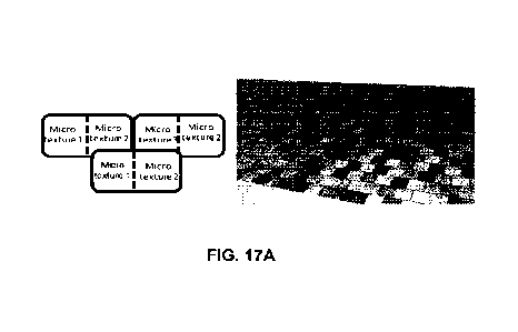
[0100] FIGs. 17A-17B show exemplary scenarios of in-tile color contrast,
according
to one embodiment. The left drawing of FIG. 17A shows that a tile can be
divided into two
equal portions, with each portion having a particular microtexture pattern.
The right drawing
of FIG. 17A shows a partial view of a roof having such tiles randomly
distributed. FIG. 17B
shows that a tile can be divided into four equal portions, with different
adjacent portions
having different microtexture patterns. The right drawing of FIG. 17B shows a
partial view
of a roof having such tiles randomly distributed.
[0101] From FIGs. 17A-17B, one can see that the in-tile color contrast not
only can
randomize the color distribution, thus hiding the difference between PV and
non-PV tiles, but
also can create a visual effect of tiles having a different size than their
original size. More
specifically, the tiles can appear smaller than their real size. For example,
in FIG. 17A, the
18
CA 03144911 2022-1-19
WO 2021/026093
PCT/US2020/044790
tiles appear to be half the size of the real tile, and in FIG. 17B, the tiles
appear to be a quarter
of the size. In certain scenarios, the smaller tiles may be aesthetically
favorable.
[0102] In addition to the appearance of different size tiles, applying
different
microtexture patterns on a single tile can also create an effect of tiles
having different offsets.
FIG. 18 shows a different scenario of in-tile color contrast, according to one
embodiment. In
FIG. 18, each tile can be divided into two portions of different sizes, and
each portion can
have a different microtexture pattern, as shown in the left drawing. The
resulting roof, shown
in the right drawing of FIG. 18, can produce a visual effect of smaller tiles
having various
offsets between adjacent rows. In general, the ability to modulate the tile
color contrast
within each tile can provide roof designers more options in designing the roof
aesthetics.
[0103] In addition to the line patterns shown in FIG. 16A, other types of
microscopic
texture can also be used to achieve the roof color randomization, as long as
features in
different texture patterns scatter light differently, including different
angles or strengths. In
addition to lines of different orientations and/or widths, to create contrast,
one can also use
spheres of different scales or depths. FIG. 19 shows a number of exemplary
microscopic
texture patterns, according to one embodiment. In FIG. 19, from top to bottom,
the size of
the features increases; and for the same feature size, the feature pattern on
the right side has a
shallower depth than the feature pattern on the left side. By applying
different micro features
on the glass cover, one can modulate the color appearance (e.g., the
lightness) of the tiles,
including both the PV and non-PV tiles.
[0104] Although the rollers and press molds can be used to create the
macrotexture
pattern superimposed with a microtexture pattern on the glass surface, there
are challenges to
implementing such techniques. First, because the front covers of the PV tiles
can be
relatively thin (e.g., 2.7 mm), the overall depth of the textures can be
limited, thus limiting
the strength of the contrast modulation. The low contrast modulation can
reduce the desired
texture aesthetics. Second, creating microtextures using rollers or press
molds can often
leave waviness on the backside of the thin glass cover, which may lower the
yield of other
tile fabrication processes, such as lamination. Moreover, the visual effect
created by the
macrotextures can depend on viewing and/or lighting angles. At certain viewing
angles, the
macrotextures may be less visible.
[0105] In some embodiments, to overcome these challenges, the textured
appearance
of the glass cover can be created without the use of macrotextures or by using
a very shallow
macrotexture. Note that the 3D appearance of a structure is in fact post-
processed by human
brains and people have used 2D images to create 3D effects by manipulating the
lighting and
19
CA 03144911 2022-1-19
WO 2021/026093
PCT/US2020/044790
shadowing. Using the same principle, one may create the appearance of depth
contrast of a
texture by modulating the brightness of the glass surface.
[0106] FIG. 20 shows an exemplary roof tile cover having a tree bark surface
texture,
according to one embodiment. More specifically, the top drawing shows the
overview of the
roof tile cover, and the bottom drawing shows the amplified view of the
texture pattern. Note
that the surface of the roof tile is substantially flat, and the perceived
texture pattern is in fact
created by changing the color or brightness of the different regions on the
flat cover.
[0107] In some embodiments, changing the color or brightness of selected
regions on
a glass cover can be achieved using a selective surface treating technique.
More specifically,
a selected portion of the glass surface can be treated to achieve one
microtexture, whereas the
other portion of the glass surface can be treated differently to achieve a
different
microtexture. The contrast between the two microtextures can create a visual
effect of a 3D
macrotexture pattern. To do so, a contour can first be created on the glass
surface, mimicking
a tree bark pattern, as shown in FIG. 21A. The contour can be generated using
a masking
technology or can be generated during the initial glass rolling process where
a very shallow
macrotexture pattern can be created. A particular type of micro structure
having a particular
reflection property can then be created inside the contour, and a different
type of micro
structure having a different reflection property can be created outside the
contour. The
different microtexture patterns can create the appearance of a 3D
macrotexture, as shown in
FIG. 21B.
[0108] FIG. 21B shows an exemplary textured glass surface, according to one
embodiment. In some embodiments, the micro structures within the contour can
be generated
by applying a matte coating on the glass surface. In further embodiments,
screen printing can
be used to apply the matte coating. The matte coating can have different
glossy levels (e.g.,
scattering properties). The portions outside the contour can be left blank
(i.e., without being
textured) or have a different type of microtexture. In the example shown in
FIG. 21B, the
tree bark pattern can be defined by lines on a flat surface or can have a very
small thickness,
depending on the coating technology.
Colored Tile
[0109] In addition to the blue or grey color that is close to the natural
color of the Si
solar cells, solar roof customers may desire other roof colors, such as
terracotta. However,
conventional coloring techniques, such as applying paint or adding pigments,
often depend on
light absorbing principles, which often result in large losses in solar cell
efficiency. An ideal
CA 03144911 2022- 1- 19
WO 2021/026093
PCT/US2020/044790
solution for adding color should provide a square shaped reflection spectrum
such that it only
reflects wavelengths of the desired color, thus resulting in lower losses in
solar cell
efficiency. In some embodiments, a multilayer thin-film stack can be applied
onto the tile
surface to efficiently generate color for the solar roof without a significant
loss of the solar
cell efficiency. Moreover, the reflection spectrum should be angle-insensitive
such that the
color of the roof does not vary significantly at different viewing angles.
[0110] FIG. 22A presents an exemplary front glass cover, according to one
embodiment. Glass cover 2200 can include a glass substrate 2202 and a
multilayer thin-film
stack 2204. Glass substrate 2202 can be textured as discussed in the previous
section.
Multilayer thin-film stack 2204 can include alternating layers of materials
having high and
low refractive indices. However, unless conventional Bragg reflectors where
the thicknesses
of the high and low index layers are periodical, the thickness of each high or
low index layer
in multilayer thin-film stack 2204 can be optimized individually, according to
a set of design
objectives. More specifically, the thickness of each layer can be selected
such that the solar
cell efficiency can be maximized, the difference between the designed and
targeted colors can
be minimized, and the amount of variation in color across a large range of
viewing angles can
also be minimized.
[0111] FIG. 22B presents an exemplary multilayer thin-film stack, according to
one
embodiment. In some embodiments, common materials that can be deposited using
chemical-vapor deposition (CVD) or physical-vapor deposition (PVD) techniques,
such as
SiO2, SiNx, and ITO, can be used to form the multilayer thin-film stack. In
the example
shown in FIG. 2213, multilayer thin-film stack 2210 can include alternating
layers of SiO2 and
Si3N4. As one can see in FIG. 22B, the thicknesses of the layers are not
periodic. Also note
that the thickness of each layer shown in FIG. 22 is for illustration purposes
only and is not
drawn to scale.
101121 In one embodiment, the thickness of each layer can be, from top to
bottom,
211 nm, 242.8 nm, 120.5 nm, 10 nm, 41.5 nm, 250 nm, 13.3 nm, and 10 nm. In a
different
embodiment, the thickness of each layer can be, from top to bottom, 110.9 nm,
253.3 nm,
137.1 nm, 249.8 nm, 169.5 nm, 252.5 nm, 34.8 nm, and 10.5 nm. FIG. 23A shows
the
reflection spectrum of a multilayer thin-film stack on a glass substrate,
according to one
embodiment. One can see a slight shift in the reflection spectrum for
different viewing
angles. Moreover, in this scheme, the amount of average solar cell efficiency
loss is roughly
7.5%, compared to up to 20% for the conventional coloring approaches. FIG. 23B
shows the
21
CA 03144911 2022-1-19
WO 2021/026093
PCT/US2020/044790
color appearance of the multilayer thin-film stack under different viewing
angles, according
to one embodiment.
Front Textured Solar Panel
[0113] Individually constructed solar roof tiles can successfully mimic the
aesthetics
of conventional roof tiles. However, producing such tiles can incur a higher
cost than
producing the conventional, less visually appealing solar panels. In addition,
mounting
individual tiles or tile modules on a roof can be more expensive than
installing larger solar
panels. In some embodiments, to reduce fabrication and installation cost, a
solar roof can
include larger solar panels having a textured front cover to create the look
of individual tiles.
More specifically, the front cover of a conventional solar panel can be
replaced using a
specially designed, textured front cover, with the texture structure including
a series of steps
to mimic the visual effect of shingled roof tiles.
[0114] FIG. 24A illustrates the side view of an exemplary solar panel,
according to
one embodiment. Solar panel 2400 can include a body 2402 and a textured front
cover 2404.
Body 2402 can be similar to the body of any conventional solar panel. More
specifically,
body 2402 can include a back cover, encapsulant, and interconnected solar
cells. Textured
front cover 2404 can be made of any suitable transparent material, including
but not limited
to: tempered glass and polyvinyl chloride (PVC). The sun-facing surface of
front cover 2404
can be textured in such a way that a series of steps and gaps can be created
to generate the
visual effect of individual roof tiles. FIG. 24B shows a partial view of the
panel, according to
one embodiment. As one can see in FIG. 24B, the steps created by a texture
technique
generate the visual effect of shingled roof tiles. In addition to the step
texturing, other surface
texturing (e.g., a tree bark texture pattern) can also be created to achieve
the desired
aesthetics.
101151 FIG. 25A illustrates the top view of an exemplary front cover of a
solar panel,
according to one embodiment. The solar panel can have a dimension similar to a
conventional panel. In this example, the solar panel can have a dimension of
1.66 m x 0.996
m. The dark lines on the front cover are the steps and gaps created via a
texturing technique.
These dark lines create the effect of individual tiles. FIG. 25B illustrates
the amplified side
view of a step on the front cover, according to one embodiment. The height of
the steps can
be roughly a few millimeters. In this embodiment, the height of a step can be
3_5 mm. In
22
CA 03144911 2022- 1- 19
WO 2021/026093
PCT/US2020/044790
some embodiments, to enhance the visual effect, the vertical surface of the
steps can be
decorated with a dark paint.
101161 In some embodiments, to prevent water leakage, the edges, including
both
vertical and horizontal edges, of the front cover can include
interlocking/overlapping
mechanisms to facilitate interlocking between a solar panel and adjacent solar
panels. More
specifically, the interlocking mechanisms can include portions of the front
cover that extend
beyond the edges of the panel body.
101171 FIG. 26A shows the top view of an exemplary solar panel front cover,
according to one embodiment. In FIG. 26A, front cover 2600 includes portions
(e.g., portion
2602) extending beyond the edges of the solar panel body, whose boundaries are
defined by
dashed box 2606. More specifically, offsets along the vertical edges are
defined as the X-
axis offsets and offsets along the horizontal edges are defined as Y-axis
offsets. As one can
see from FIG. 26A, the X-axis offsets can have an interdigitated pattern,
where one row of
perceived tiles extends in one direction and the adjacent row of tiles extends
in the opposite
direction. This arrangement can facilitate horizontal interlocking between
adjacent solar
panels on the roof. FIG. 26B shows the perspective view of the solar panel
front cover,
according to one embodiment.
101181 FIG. 27 shows multiple interlocking solar panels, according to one
embodiment. The dashed line marks the borders among the interlocking solar
panels.
101191 In general, embodiments of the present invention provide a cost-
effective way
for achieving a desired aesthetic of a solar roof without sacrificing solar
cell efficiency. By
selecting solar cells with low color flop and by matching the background color
with the
natural color of the solar cells, one can reduce the amount of cell glow and
effectively hide
the solar cells. Moreover, by measuring the solar cell color and by grouping
the solar cells
based on their color during tile manufacture, one can ensure that most files
have a single cell
color and color distribution across the roof can be substantially homogenous.
Other color
control schemes can also include introducing color contrast among the tiles
through surface
treatment. Tiles with different brightness or lightness can then be randomly
distributed
across the roof to distract the viewers' attention from the difference between
PV tiles and
non-PV tiles.
[0120] The foregoing descriptions of various embodiments have been presented
only
for purposes of illustration and description. They are not intended to be
exhaustive or to limit
the present system to the forms disclosed. Accordingly, many modifications and
variations
23
CA 03144911 2022- 1- 19
WO 2021/026093
PCT/US2020/044790
will be apparent to practitioners skilled in the art. Additionally, the above
disclosure is not
intended to limit the present system.
24
CA 03144911 2022- 1- 19