Note: Descriptions are shown in the official language in which they were submitted.
ROLLER MILL AND METHOD FOR OPERATING A ROLLER MILL
The invention relates to a roller mill having peripheral elements for
comminuting
granular material, and to a method for operating a roller mill.
Roller mills are typically used for comminuting ground material such as, for
example,
limestone, clinker, or similar rocks. In the comminution of ground material in
a roller mill
it arises that ground material exits the milling gap laterally without having
completely or
at all passed the milling gap. This leads to a reduction of the throughput
rate of the
machine and to an increase in the grinding revolutions, which is associated
with an
enormous input of energy.
In order for the lateral outflow of ground material from a milling gap
configured between
the grinding rollers of a roller mill to be influenced in a controlled manner
it is known for
peripheral elements to be disposed on one of the grinding rollers. Such a
roller mill
having peripheral elements is known from DE 20 2014 006 837 U1, for example.
An
increased specific grinding pressure acts on the peripheral elements, said
increased
specific grinding pressure leading to high stress on the peripheral elements
and thus
often leading to wear or breakage on the peripheral elements.
Proceeding therefrom, it is an object of the present invention to provide a
roller mill
having peripheral elements, wherein the peripheral elements are subjected to
less stress
and wear.
A roller mill for comminuting granular material according to a first aspect
comprises a
first grinding roller and a second grinding roller which are disposed so as to
be opposite
1
Date Recue/Date Received 2023-03-03
CA 03145149 2021-12-23
and drivable in a counter-rotating manner, wherein a milling gap is configured
between
the grinding rollers. At least one of the grinding rollers on an end region of
a grinding
roller end comprises a peripheral element which is configured in such a manner
that said
peripheral element extends across the milling gap and at least partially
covers the
opposite grinding roller on the end side.
A scraping element for removing material is disposed on the end region of the
grinding
roller end that is provided with a peripheral element. The scraping element
serves in
particular for at least partially removing material that has accumulated on
the end region
of the grinding roller. The material is scraped by the scraping element in the
operation of
the roller mill, wherein the grinding rollers rotate in a counter-rotating
manner. The
scraping element is preferably disposed on the end region of the grinding
roller in such a
manner that said scraping element does not contact the grinding roller. The
end region of
the grinding roller comprises, for example, the end side of the grinding
roller, the
grinding roller surface adjacent thereto, as well as a region which surrounds
the grinding
roller surface and in which material accumulates. For example, such a region
comprises a
height of more than or equal to 2 mm to 10 mm, in particular more than or
equal to
4 mm to 8 mm, preferably 5 mm.
.. The peripheral element comprises in particular an encircling circular ring,
preferably a
circular disk. The peripheral element is in particular attached to the end
side of the
respective grinding roller, for example screw-fitted or welded thereto.
One end-side gap is in each case preferably configured between the peripheral
elements
.. and the end side of the respective opposite grinding roller. An end-side
gap prevents a
collision between the peripheral element and the end region of the respective
opposite
grinding roller in the event of the grinding rollers running off track,
wherein the opposite
grinding rollers are disposed so as not to be mutually parallel.
2
Date recue/ date received 2021-12-23
CA 03145149 2021-12-23
The grinding rollers comprise in particular a roller main body, wherein the
peripheral
element is releasably connected to the roller main body of the respective
grinding roller.
The grinding roller preferably comprises a drive shaft for driving the
grinding roller, the
roller main body being disposed on said drive shaft. A releasable disposal of
the
peripheral elements on the roller main body offers the advantage of a rapid
and simple
replacement of the peripheral elements in the event of wear. The peripheral
elements
are adhesively bonded, soldered/brazed, welded, or screw-fitted to the roller
main body,
for example, and preferably comprise a wear-protection feature. The wear-
protection
feature is in particular disposed on the internal face of the peripheral
element that points
in the direction of the milling gap. Such a wear-protection feature comprises
a wear-
resistant coating, for example, such as a surface-welding, wear-protection
elements, or
wear-protection coatings. The peripheral elements are preferably configured
from steel.
In the operation of the roller mill, a material layer is usually formed on the
surface of the
grinding rollers, said material layer having the effect of an autogenous wear-
protection
feature of the roller surface. According to one insight of the inventor, said
wear-
protection layer is thicker on those end regions of the roller ends that are
provided with
peripheral elements than, on the remaining regions of the grinding rollers.
This leads to
an increased grinding pressure on account of which the peripheral elements are
more
heavily stressed and wear or fail more often. The material accumulation on the
grinding
roller ends on the peripheral elements is reliably prevented by means of the
scraping
elements. The risk of increased wear and of a failure of the peripheral
elements is
minimized on account thereof.
The roller mill according to the invention has a measuring device for
determining the
layer thickness of ground material on at least one of the grinding rollers
and/or for
determining the stress of the peripheral element. The roller mill furthermore
has a
control device which is connected to the measuring device and, as a function
of the
determined layer thickness and or stress, is configured for decreasing or
increasing the
spacing of the scraping element from the grinding roller. The control device
comprises,
3
Date recue/ date received 2021-12-23
CA 03145149 2021-12-23
for example, a computer and is preferably connected to the measuring device in
such a
manner that the data collected by means of the measuring device, such as the
stress
and/or the layer height of the ground material on the grinding roller, is
transmitted to
the control device. The stress comprises the forces acting on the peripheral
element or
the relative elongation of the peripheral element, for example.
The scraping element is preferably disposed so as to be spaced apart from the
peripheral
element and/or the end region of the grinding roller. The spacing between the
scraping
element and the peripheral element and/or the end region of the grinding
roller is
preferably more than or equal to 2 mm to 10 mm, in particular 4 mm to 8 mm,
preferably
5 mm. A spacing between the scraping element and the peripheral element and/or
the
end region of the grinding roller prevents contact between the scraping
element and the
grinding roller and thus minimizes the wear on the scraping element.
The scraping element is disposed in such a manner that the spacing between the
scraping
element and the peripheral element and/or between the scraping element and the
end
region of the grinding roller is capable of being set. In particular, the
thickness of the
material layer on the end regions of the grinding rollers should not exceed a
specific
value of, for example, 2 mm to 10 mm, in particular 4 mm to 8 mm, preferably 5
mm. A
spacing that is capable of being set ensures that the spacing between the
scraping
element and the peripheral element and/or the end region of the grinding
roller is kept
constant in the event of wear on the scraping element. Additionally, the
service life of
the scraping element is extended, and a replacement in the event of wear is
not
required.
Each of the grinding rollers on an end region of a roller end preferably has a
peripheral
element which is configured in such a manner that said peripheral element
extends
across the milling gap and at least partially covers the opposite grinding
roller on the end
side. In particular, the peripheral elements are disposed so as to be
diagonally opposite
in terms of the end regions of the grinding rollers. The scraping element
extends in
4
Date recue/ date received 2021-12-23
CA 03145149 2021-12-23
particular along a peripheral element. In particular, the scraping element in
the radial
direction of the grinding roller extends so as to be parallel or oblique to
the peripheral
element, for example. The spacing between the peripheral element and the
scraping
element is preferably consistent across the length of the scraping element.
According to a first embodiment, the scraping element is attached to a holder,
wherein
the holder is configured so as to be movable in the direction of the grinding
roller. For
example, the holder extends substantially in the radial direction of the
grinding roller.
The holder preferably comprises the spindle or a telescopic bar, wherein said
spindle or
telescopic bar are in each case able to be driven by means of an electric
motor, for
example, or manually by means of a handwheel, such that the holder is moved in
the
direction of the grinding roller or away from the grinding roller. The holder
is preferably
movable in a linear manner. The scraping element is preferably attached to the
holder in
a releasable manner, for example by means of screws.
According to a further embodiment, the roller mill has a first measuring
device for
determining the layer height of ground material on the grinding roller, and a
second
measuring device for determining the stress of the peripheral element. The
first
measuring device is preferably attached to a machine frame which is stationary
relative
to the rotating grinding rollers. The first measuring device is in particular
disposed in such
a manner that said first measuring device determines the layer height of the
ground
material on the grinding roller at the upper reversal point of said ground
material during
the rotation of the grinding roller. The scraping elements in the rotating
direction of the
grinding roller are preferably disposed at the position ahead of the upper
reversal point.
The second measuring device is attached to the peripheral element, for
example. The
roller mill preferably has two each of the first and of the second measuring
device,
wherein one second measuring device is attached to each peripheral element,
and one
first measuring device is attached to each end region of a grinding roller
provided with a
peripheral element. The first and the second measuring device are in each case
preferably connected to the control device in order for the determined
measured data to
5
Date recue/ date received 2021-12-23
CA 03145149 2021-12-23
be transmitted. The plurality of measuring devices serve for reliably
monitoring each
peripheral element of the roller mill.
According to a further embodiment, the first measuring device is an optical
measuring
device, in particular a laser measuring device, an infrared measuring device
or an
electromagnetic measuring device such as a radio measuring device (microwaves
in the
range of 1 ¨ 300 GHz). The measuring method hereunder is to be understood to
be the
optical measuring method, the laser measuring method as well as the radar
measuring
method. In the case of the radar measurement, the measuring device is
preferably
attached above the grinding roller so as to be at a previously known spacing
from the
surface of the grinding roller. The layer height is preferably determined by
means of an
optical measuring method or the radar measurement in a lateral peripheral
region of the
grinding roller. It is likewise conceivable that a surface region which
extends across the
entire width and length of the grinding roller, or only across part of the
grinding roller,
for example the end region, is detected in particular by means of radar
measurement. In
such a radar measurement, the surface of the ground material on the grinding
roller is
detected in a planar manner, and the highest value of the layer height in this
area is
determined, for example. For example, a plurality of measuring devices that
are attached
above the surface of the grinding roller, for example so as to be uniformly
spaced apart
across the circumference, so as to preferably detect a surface region of the
grinding roller
and to determine, preferably in a planar manner, the layer height in this
region. For
example, the height of the ground material is determined at a multiplicity of
individual,
mutually spaced apart, measuring points, a two-dimensional image of the ground
material surface being determined therefrom by means of interpolation, for
example.
The measuring methods for determining the layer height represent a simple and
reliable
possibility for determining the layer height during the operation of the
roller mill.
According to a further embodiment, the second measuring device comprises a
strain
gauge. The second measuring device comprises in particular a plurality of
strain gauges,
preferably 2, 4, 6, 8 or 10 strain gauges. The strain gauges are attached to
the peripheral
6
Date recue/ date received 2021-12-23
CA 03145149 2021-12-23
element so as to be uniformly spaced apart on the circumference, for example.
A strain
gauge is in particular attached to a screw by means of which the peripheral
element, or a
segment of the peripheral element, is connected to the main body of the
roller. The
strain gauge determines the relative elongation or compression of the region
to which
.. said strain gauge is attached, the stresses arising on said region, in
particular the forces
acting on the peripheral elements and/or the screws, being determined
therefrom.
According to a further embodiment, the control device is configured in such a
manner
that said control device decreases the spacing between the scraping element
and the
grinding roller if the layer height exceeds a previously determined threshold
value. The
threshold value is, for example, 2 mm to 10 mm, particularly 4 mm to 8 mm,
preferably
5 mm. The spacing is preferably increased if the layer height undershoots the
previously
determined threshold value. When the layer height exceeds the previous
determined
threshold value, a conclusion can be drawn with respect to wear on the
scraping
element. The threshold value is preferably stored in the control device. The
worn region
of the scraping element is compensated for by decreasing the spacing.
Excessive wear on
the scraping element is likewise counteracted when the spacing is increased.
The spacing
is in particular to be understood to be the spacing between the scraping
element and the
surface of the main body of the roller, in particular the grinding face of the
grinding
.. roller.
According to a further embodiment, the control device is configured in such a
manner
that said control device decreases the spacing between the scraping element
and the
grinding roller if the stress, in particular the elongation of the peripheral
element,
exceeds a previously determined threshold value. The spacing by means of the
control
device is preferably increased when the stress, in particular the relative
elongation of the
peripheral element, undershoots the previously determined threshold value.
According to a further embodiment, the measuring device in the rotating
direction of the
grinding roller is disposed between the scraper and the milling gap. As a
result, the
7
Date recue/ date received 2021-12-23
CA 03145149 2021-12-23
function of the scraper is monitored, wherein the layer thickness is
determined at a
location where no further material is pressed onto the roller.
The scraping element is preferably disposed in such a manner that said
scraping element
removes material that in the operation of the roller mill has accumulated on
the
peripheral element and/or on the end region of the grinding roller. In
particular, the
scraping element is disposed so as to be stationary or movable relative to the
rotatable
grinding rollers such that the grinding rollers rotate relative to the
scraping element.
The scraping element is preferably disposed in such a manner that said
scraping element
in the operation of the roller mill removes material that has accumulated on
the
peripheral element and/or on the end region of the grinding roller. In
particular, the
scraping element is disposed so as to be stationary or movable relative to the
rotatable
grinding rollers so that the grinding rollers rotate relative to the scraping
element.
According to a further embodiment, the roller mill comprises a stationary
machine frame,
and the scraping element is attached to the machine frame. The machine frame
comprises, for example, a plurality of frame elements which are connected to
bearing
jewels of the grinding rollers such that the grinding force acting on the
grinding rollers is
transmitted to the machine frame. A machine frame of a roller mill comprises
in
particular a frame element which extends substantially in the axial direction
of the
grinding rollers and to which the scraping element is preferably attached. The
scraping
element extends from the machine frame in the direction of the grinding
roller, in
particular in the end region of the grinding roller.
The roller mill according to a further embodiment comprises at least two
scraping
elements which are disposed on end regions of dissimilar roller ends of the
grinding
roller. The scraping elements are preferably disposed on opposite end regions
of a
grinding roller. Each scraping element is preferably attached to in each case
one holder
which is attached so as to be movable in the direction of the grinding roller.
8
Date recue/ date received 2021-12-23
CA 03145149 2021-12-23
According to a further embodiment, the scraping element comprises a scraping
plate
which is configured from a wear-resistant material such as, for example,
tungsten
carbide. The scraping plate is disposed on that end of the scraping element
that faces the
grinding roller and in the operation of the roller mill is in contact with the
material to be
scraped. The scraping plate is therefore subjected to high wear, wherein a
wear-resistant
material extends the service life of the scraping plate.
The scraping element according to a further embodiment comprises an arm to
which the
scraping plate is releasably fastened. For example, the scraping plate is
clamped or
.. screw-fitted to the arm. The scraping plate in the direction of the
grinding roller
preferably projects beyond the arm. A releasable fastening of the scraping
plate of the
scraping element enables the scraping plate to be readily replaced, said
scraping plate
representing the most wear-intensive region of the scraping element.
Replacement of
the entire scraping element in the event of wear is thus not required.
The invention also comprises a method for operating a roller mill for
comminuting
granular material having a first grinding roller and the second grinding
roller which are
disposed so as to be opposite and drivable in a counter-rotating manner,
wherein a
milling gap is configured between the grinding rollers and wherein at least
one of the
grinding rollers on an end region of a grinding roller comprises a peripheral
element
which is configured in such a manner that said peripheral element extends
across the
milling gap and at least partially covers the opposite grinding roller on the
end side,
wherein a scraping element for at least partially removing material is
disposed on the
end region of the grinding roller that is provided with a peripheral element,
wherein the
method comprises at least the step of:
determining a layer height of ground material on at least one of the grinding
rollers;
and/or
determining a stress of the peripheral element; and
setting the spacing between the scraping element and the grinding roller as a
function of
.. the determined layer height and/or stress.
9
Date recue/ date received 2021-12-23
CA 03145149 2021-12-23
The advantages described in the context of the grinding roller apply in an
analogous
manner to the method for operating a roller mill for comminuting granular
material.
The material is preferably removed on two end regions of the grinding roller
that are in
each case provided with one peripheral element. According to a further
embodiment, the
spacing is decreased if the determined layer height exceeds a previously
determined
threshold value. According to a further embodiment, the spacing is decreased
if the
stress exceeds a previously determined threshold value.
Description of the drawings
The invention is explained in more detail hereunder by means of a plurality of
exemplary
embodiments with reference to the appended figures in which:
fig. 1 shows a schematic illustration of a fragment of a roller mill in a plan
view,
according to an exemplary embodiment;
fig. 2 shows a schematic illustration of a fragment of a roller mill in a plan
view,
according to a further exemplary embodiment;
fig. 3 shows a schematic illustration of a fragment of a grinding roller
having scraping
elements in a perspective view, according to an exemplary embodiment;
fig. 4 shows a schematic illustration of a scraping element in a perspective
view,
according to an exemplary embodiment; and
fig. 5 shows a schematic illustration of the scraping element in fig. 4, in a
perspective
rear view.
Date recue/ date received 2021-12-23
CA 03145149 2021-12-23
Fig. 1 shows a roller mill 10 having a first grinding roller 12 and a second
grinding roller 14
which comprise in each case a substantially cylindrical roller main body. The
grinding
rollers 12, 14 are disposed so as to be opposite and drivable in a counter-
rotating
manner. A milling gap 16 which extends in the axial direction is configured
between the
grinding rollers 12, 14. The grinding rollers 12, 14 are disposed so as to be
almost
mutually parallel such that the milling gap 16 extending between the grinding
rollers 12,
14 comprises an almost consistent width. Each of the grinding rollers 12, 14
furthermore
comprises a drive shaft 30, 32 which extends along the central axis extends
through the
respective grinding roller 12, 14 and drives the grinding rollers so as to
rotate about the
central axes of the latter. The first and the second grinding roller 12, 14
comprise
identical diameters, wherein the first grinding roller 12 can be longer than
the second
grinding roller 14.
The grinding rollers 12, 14 comprise in each case a first end region 24, 28
and a second
end region 22, 26 which are disposed on opposite ends of the grinding roller.
The first
end region 24 of the first grinding roller 12 is disposed so as to be opposite
the first end
region 28 of the second grinding roller 14, wherein the second end region 22
of the first
grinding roller 12 is disposed so as to be opposite the second end region 26
of the second
grinding roller 14.
By way of example, the first grinding roller 12 comprises two peripheral
elements 18, 20
which are in each case attached to an end region of the grinding roller 12.
The first
peripheral element 18 is attached to the first peripheral region 22 of the
first grinding
roller 12 and in the radial direction extends beyond the milling gap 16 such
that said first
peripheral element 18 partially covers the end side of the second grinding
roller 14 on
the first end region 26. The second peripheral element 20 is attached to the
second end
region 24 of the first grinding roller 12 and in the radial direction extends
beyond the
milling gap 16 such that said second peripheral element 20 partially covers
the end side
of the second grinding roller 14 the second end region 28. One end-side gap
34, 36 is in
11
Date recue/ date received 2021-12-23
CA 03145149 2021-12-23
each case configured between the peripheral elements 18 and the respective end
side of
the second grinding roller 14.
The peripheral elements 18, 20 preferably comprise in each case an encircling
circular
ring which can also be composed of segments, for example, and is attached to
the
respective grinding roller 12, 14 (not illustrated). For example, the
peripheral elements
18, 20 are attached to the end side or to the external circumference of the
grinding
roller, in particular the respective roller main body. For example, an
encircling groove in
which one peripheral element 18, 20 is in each case disposed is disposed on
the external
circumference of the respective grinding roller 12, 14. The peripheral
elements 18, 20 are
configured from a wear-resistant material such as, for example, steel, and
comprise a
wear-resistant coating or a plurality of, for example, plate-like wear-
protection elements
in particular on the internal side that points toward the milling gap 16. The
peripheral
elements 18, 20 comprise a thickness of, for example, 10 mm to 100 mm, and
cover the
opposite grinding rollers 12, 14 by approximately 2 to 20%, in particular 4 to
10%,
preferably 3 to 6%, of the roller diameter.
Fig. 2 shows a further embodiment of a grinding roller having peripheral
elements 18, 20,
wherein the grinding roller corresponds substantially to the grinding roller
illustrated in
fig. 1 but differs in that each of the grinding rollers 12, 14 in the
exemplary embodiment
in fig. 2 comprises in each case one peripheral element 18, 20. The first and
the second
grinding roller 12, 14 comprise identical diameters and identical lengths and
are
configured so as to be of substantially identical construction.
The peripheral elements 18, 20 in terms of the end regions 22 to 28 of the
grinding
rollers 12, 14 are disposed so as to be diagonally opposite. The first
grinding roller 12 on
the first end region 24 thereof comprises a peripheral element 18 which in the
radial
direction extends across the milling gap 16 and partially covers the end side
of the
second grinding roller 14 on the first end region 28. The second grinding
roller 14 on the
second end region 26 thereof comprises a peripheral element 20 which in the
radial
12
Date recue/ date received 2021-12-23
CA 03145149 2021-12-23
direction extends across the milling gap 16 and partially covers the end side
of the first
grinding roller 12 on the second peripheral region 22 thereof. The second
peripheral
element 20 in terms of the first peripheral element 18 is disposed on the
diagonally
opposite end region 26 of the second grinding roller 14. The grinding rollers
12, 14 are
disposed so as to be offset in the axial direction such that a first end-side
gap 34 is
configured between the first peripheral element 18 and the end side of the
second
grinding roller 14, and a second end-side gap 36 is configured between the
second
peripheral element 20 and the end side of the first grinding roller 12. The
first and the
second end-side gap 34, 36 extend in each case in the radial direction.
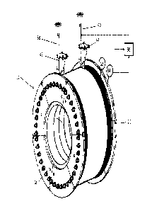
Fig. 3 shows a fragment of a first grinding roller 12 of the roller mill 10
according to fig. 1.
By way of example, the peripheral elements 18, 20 comprise a plurality of part-
circular
segments which are each screwed onto the end face of a respective end region
of the
grinding roller 12. Each segment is fastened to the end side of the grinding
roller 12 with
a plurality of screws or bolts.
Fig. 3 also shows two scraping elements 42, 44 which in each case are attached
to a
holder 38, 40 and in each case extend in the direction of a respective end
region of the
grinding roller 12. The holders 38, 40 are preferably in each case fastened to
a machine
frame (not illustrated), wherein in particular the grinding rollers 12, 14 are
situated on
the machine frame. The scraping elements 42, 44 are disposed so as to be
spaced apart
from the grinding roller 12 and the peripheral element 18, 20 of the grinding
roller 12
such that the scrapers do not touch the grinding roller 12 and the peripheral
elements
18, 20. The first scraping element 42 is attached in such a manner that it
lies opposite the
first end region 22 of the grinding roller 12, wherein the first scraping
element 42 in the
radial direction of the grinding roller 12 extends along the first peripheral
element 18 and
is aligned so as to be substantially parallel to the latter. However, other
alignments are
also possible. The second scraping element 44 in a corresponding manner is
disposed on
the second end region 24 and the second peripheral element 20 of the grinding
roller 12.
The scraping elements 42, 44 extend in each case along the face of the
peripheral
13
Date recue/ date received 2021-12-23
CA 03145149 2021-12-23
elements 18, 20 that points inward in the axial direction of the grinding
roller 12. The
scraping elements 42, 44 are configured so as to be mutually identical, for
example.
The holders 38, 40 are preferably configured in such a manner that said
holders 38, 40
are movable in and/or counter to the direction of the grinding roller 12 such
that, in a
movement of the holders 38, 40 in or counter to the direction of the grinding
roller, the
spacing between the grinding roller, in particular the surface of the grinding
roller 12, 14,
and the scraping element 42, 44 is decreased or increased. The holders 38, 40
are
preferably able to be moved in a linear manner in the direction of the
grinding roller 12,
14, or away from the grinding roller 12, 14. The holders 38, 40 are, for
example, in each
case a telescopic bar or a spindle which are preferably able to be driven by
means of an
electric motor, not illustrated, or manually by means of a handwheel.
Fig. 3 furthermore shows a first measuring device 62 for determining the layer
thickness
of the ground material adhering to the surface of the grinding roller. The
first measuring
device 62 is an optical measuring device, for example, wherein the layer
thickness is
determined by means of a laser, for example. The first measuring device 62 is
preferably
disposed in such a manner that the layer thickness of the ground material is
determined
on an end region of the grinding roller 12, 14, in particular close to one of
the peripheral
elements 18, 20 or on one of the latter. The measuring device 62 in the
rotating direction
of the grinding roller 12 is preferably attached behind the scraping element
42, 44 such
that the layer thickness is determined circumferentially between the scraping
element
42, 44 and the milling gap 16 during the operation of the roller mill 10. The
rotating
direction of the grinding roller 12 is illustrated by an arrow in fig. 3. The
first measuring
device 62 is attached to the previously described machine frame, for example,
and
disposed so as to be stationary relative to the rotatable grinding rollers 12,
14.
The roller mill 10 furthermore has a second measuring device 64 which is
attached to a
peripheral element 18, 20 and is configured in such a manner that said second
measuring
device 64 determines the stress acting on the respective peripheral element
18, 20.
14
Date recue/ date received 2021-12-23
CA 03145149 2021-12-23
Stress is to be understood as a force acting on the peripheral element 18, 20
and/or the
stresses arising in the respective peripheral element 18, 20, for example. The
second
measuring device 64 is, for example, one or a plurality of strain gauges. The
strain gauge
is attached to the peripheral element 18, 20, for example, so as to determine
the arising
stresses, in particular the forces acting on the peripheral element. It is
likewise
conceivable for a plurality of strain gauges to be attached to different
positions on the
peripheral element 18, 20. For example, one or a plurality of screws for
fastening the
peripheral element 18, 20 to the main body of the grinding roller 12, 14 are
in each case
provided with one strain gauge. The second measuring device 64 in the rotating
direction
of the grinding roller 12, 14 is preferably disposed behind the scraping
element 42, 44
and ahead of the milling gap 16.
The roller mill 10 furthermore comprises a control device 66 for setting the
spacing
between the scraping element 42, 44 and the surface of the grinding roller 12,
14. The
control device 66 is connected to the first and/or the second measuring device
62, 64 in
such a manner that the data determined by means of the respective measuring
device
62, 64 is transmitted to the control device 66. The control device 66 is
furthermore
connected to the holder 38, 40, preferably to both holders 38, 40, of the
scraping
elements 42, 44. The control device 66 is in particular connected to an
electric motor
which moves the holders 38, 40 of the scraping elements 42, 44, preferably in
the
direction of the grinding roller 12, 14 or away from the grinding roller 12,
14. The control
device 66 is connected to the holders 38, 40 and/or the electric motor in such
a manner
that said control device 66 by means of a control signal for movement can move
the
holders in the direction of the grinding roller 12, 14 or away from the
grinding roller 12,
14.
Fig. 3 only shows the disposal of the scraping elements 42, 44 on a roller
mill according to
fig. 1. A roller mill 10 illustrated in fig. 2 by way of example likewise
comprises two
scraping elements 42, 44. Each grinding roller 12, 14 of the roller mill 10
illustrated in fig.
2 comprises in each case one scraping element 42, 44 which is attached, for
example, to
Date recue/ date received 2021-12-23
CA 03145149 2021-12-23
a roller frame and, in a manner corresponding to the exemplary embodiment in
fig. 3,
extends in the direction of a respective end region of the grinding roller 12,
14 that
comprises a peripheral element 18, 20. It is likewise conceivable that one
first measuring
device 62 is attached to each end region of the grinding roller, and one
second measuring
device 64 is attached to each peripheral element 18, 20. All measuring devices
62, 64 are
connected to a control device 66, for example.
For setting the spacing between the scraping element 42, 44 and the surface of
the
grinding roller 12, 14, the control device 66 compares the measured values
transmitted
by the first and/or the second measuring device 62, 64 with a corresponding,
previously
determined threshold value, for example. For example, the control device 66
compares
the value of the layer height of the ground material on the grinding roller
12, 14
transmitted by means of the first measuring device 62 with a previously
determined
threshold value of the layer height, said threshold value being stored in the
control
device 66. The control device 66 is preferably configured and specified in
such a manner
that said control device 66, if the determined layer height exceeds the
previously
determined threshold value, decreases the spacing between the respective
scraping
element 42, 44 and the surface of the respective grinding roller 12, 14. To
this end, the
control device 66 transmits a control signal to the electric motor, for
example, or to the
holders 38, 40 such that the holders 38, 40 and the scraping elements 42, 44
fixedly
attached thereto are moved in the direction of the grinding roller 12, 14, in
particular in
the direction of the surface of the grinding roller, and the spacing between
the scraping
elements 42, 44 and the surface of the grinding roller 12, 14 is decreased.
The previously
determined threshold value of the layer height is, for example, 2 mm to 10 mm,
particularly 4 mm to 8 mm, preferably 5 mm. The control device 66 is
preferably
configured and specified in such a manner that said control device 66, if the
determined
layer height undershoots the previously determined threshold value, increases
the
spacing between the respective scraping element 42, 44 and the surface of the
respective grinding roller 12, 14. An increased layer thickness of ground
material on the
grinding roller 12, 14 can be traced back to wear on the scraping element 42,
44, wherein
16
Date recue/ date received 2021-12-23
CA 03145149 2021-12-23
decreasing the spacing of the scraping element 42, 44 from the surface of the
grinding
roller corresponds to a wear readjustment of the scraping element 42, 44 such
that the
wear on the scraping element 42, 44 is compensated for.
.. For example, the control device 66 compares the value of the stress,
preferably of the
elongation of the peripheral elements 18, 20, and/or the forces acting on the
peripheral
elements 18, 20 and/or the screws, transmitted by means of the second
measuring
device 64 with a previously determined threshold value of the respective
stress,
preferably of the elongation, that is stored in the control device 66. The
control device 66
is preferably configured and specified in such a manner that said control
device 66, if the
determined stress, in particular the elongation, exceeds the previously
determined
threshold value, decreases the spacing between the respective scraping element
42, 44
and the surface of the respective grinding roller 12, 14. This preferably
takes place as has
been described above. The control device 66 is preferably configured and
specified in
such a manner that said control device 66, if the determined stress, in
particular the
elongation, undershoots the previously determined threshold value, decreases
the
spacing between the respective scraping element 42, 44 and the surface of the
respective grinding roller 12, 14.
Fig. 4 shows an enlarged view of an exemplary scraping element 42, 44. The
scraping
element 42, 44 comprises a fastening plate 46 which in the assembled position
of the
scraping element 42, 44 is attached to the holder 38, 40. The fastening plate
comprises a
plurality of fastening bores 48 which serve for fastening the scraping element
42, 44 to
the holder 38, 40, for example by means of screws.
An arm 50 is attached to the fastening plate 46, said arm 50 in relation to
the fastening
plate 46 extending at an angle of, for example, approximately 30 to 60', in
particular
approximately 45 , in the direction of the grinding roller 12, 14 (not
illustrated). A
scraping plate 52 which is fastened to the arm 50 by means of two screws 54
and a
clamping plate 56 is attached to the arm 50. The scraping plate in a manner
parallel to
17
Date recue/ date received 2021-12-23
CA 03145149 2021-12-23
the arm 50 extends beyond the end of the arm that faces away from the
fastening plate
46 such that the scraping plate 52 on the arm 50 projects in the radial
direction of the
grinding roller 12, 14. The scraping plate 52 is clamped between the clamping
plate 56
and the arm 50 such that said scraping plate is easy to replace in the event
of wear. In an
exemplary manner, the scraping plate 58 is disposed in a clamping receptacle
58 which is
disposed between the clamping plate 56 and the arm 50 and is clamped by means
of the
clamping plate 56 and the screws 54.
The front edge of the scraping plate 52 in the exemplary embodiment in fig. 4
extends at
an angle in relation to the surface of the respective grinding roller 12, 14
such that the
spacing between the scraping plate 52 and the surface of the grinding roller
12, 14 is less
in the direction of the grinding roller end. The angle between the scraping
plate 52 and
the surface of the grinding roller 12, 14 is, for example, 45 to 135 . It is
likewise
conceivable that the front edge of the scraping plate 52 extends so as to be
substantially
parallel to the surface of the respective grinding roller 12, 14, in
particular in the axial
direction of the grinding roller. The lateral face of the scraping plate 52 as
well as the
lateral face of the arm 50 extend along the respective peripheral element 18,
20. In
particular, a gap of 2 mm to 10 mm, preferably 4 mm to 8 mm, in particular 5
mm, is
configured between the scraping element 42, 44 and the surface of the grinding
roller 12,
14.
The fastening plate 46, the arm, the clamping receptacle 58, and the clamping
plate 56
are configured from steel, for example. The scraping plate is configured from
a highly
wear-resistant material such as tungsten carbide, for example.
Fig. 5 shows a rear view of the scraping element 42, 44 in fig. 4. The arm 50
in an
exemplary manner comprises a substantially U-shaped profile, wherein the
clamping
plate 56 and the clamping receptacle 58 are attached to the arm 50 by means of
screws
54 and nuts.
18
Date recue/ date received 2021-12-23
CA 03145149 2021-12-23
The peripheral elements 18, 20 in the operation of the roller mill 10 prevent
material
laterally exiting the milling gap 16. An autogenous wear-protection feature is
constructed
on the surface of the grinding rollers 12, 14 on account of the accumulation
of material.
The scraping elements 42, 44 during the rotation of the grinding roller 12, 14
scrape
material that has accumulated on the end regions of the grinding roller 12, 14
and thus
ensure that the autogenous wear-protection layer does not exceed a specific
thickness
even in the end regions of the grinding rollers 12, 14 to which the peripheral
elements
are attached such that the peripheral elements are reliably protected against
high
pressure on account of accumulated material.
19
Date recue/ date received 2021-12-23
CA 03145149 2021-12-23
List of reference signs
Roller mill
12 First grinding roller
14 Second grinding roller
5 16 Milling gap
18 First peripheral element
Second peripheral element
22 First end region of the first grinding roller
24 Second end region of the first grinding roller
10 26 Second end region of the second grinding roller
28 First end region of the second grinding roller
Drive shaft of the first grinding roller
32 Drive shaft of the second grinding roller
34 First end-side gap
15 36 Second end-side gap
38 Holder
Holder
42 First scraping element
44 Second scraping element
20 46 Fastening plate
48 Fastening bores
Arm
52 Scraping plate
54 Screws
25 56 Clamping plate
58 Clamping receptacle
Nut
62 First measuring device
64 Second measuring device
30 66 Control device
Date recue/ date received 2021-12-23