Language selection

Search

Patent 3145630 Summary

Third-party information liability

Some of the information on this Web page has been provided by external sources. The Government of Canada is not responsible for the accuracy, reliability or currency of the information supplied by external sources. Users wishing to rely upon this information should consult directly with the source of the information. Content provided by external sources is not subject to official languages, privacy and accessibility requirements.

Claims and Abstract availability

Any discrepancies in the text and image of the Claims and Abstract are due to differing posting times. Text of the Claims and Abstract are posted:

  • At the time the application is open to public inspection;
  • At the time of issue of the patent (grant).
(12) Patent Application: (11) CA 3145630
(54) English Title: MANUAL CERAMIC CUTTER WITH ADJUSTABLE SET-SQUARE
(54) French Title: OUTIL DE COUPE MANUEL DE CERAMIQUE A EQUERRE REGLABLE
Status: Examination
Bibliographic Data
Abstracts

English Abstract

A manual ceramic cutter with an adjustable set-square, having a set-square (1) installed at one of the longitudinal extremities of a base (2) for supporting the ceramic items to be cut, and a manually-operated cutting head (3) installed with the possibility of displacement along a number of longitudinal guides (4). This cutter comprises adjustment means (13, 14) of the perpendicularity of the set-square (1) with regard to a cutting line (L1) of the cutter, and fixing means (11, 12) of the set-square (1) to the base (2). It further comprises visual verification means of the perpendicularity of the set-square (1) with regard to the cutting line (L1).


French Abstract

L'invention concerne un outil de coupe manuel de céramique à équerre réglable, qui comprend une équerre (1) montée sur une des extrémités longitudinales d'une base (2) de support des pièces de céramique à couper et une tête de coupe (3) à actionnement manuel montée avec la possibilité de se déplacer le long de guides longitudinaux (4). Cet outil de coupe comprend des moyens de réglage (13, 14) de la perpendicularité de l'équerre (1) par rapport à une ligne de coupe (L1) de l'outil de coupe et des moyens de fixation (11, 12) de l'équerre (1) à la base (2). L'invention concerne également des moyens de vérification visuelle de la perpendicularité de l'équerre (1) par rapport à la ligne de coupe (L1).

Claims

Note: Claims are shown in the official language in which they were submitted.

CA 03145630 2021-12-30
6
CLAIMS
1. A manual ceramic cutter with adjustable set-square; comprising: a set-
square (1) installed at one of the longitudinal extremities of a base (2) for
supporting the ceramic items to be cut and defining a lateral supporting line
(L2)
of the ceramic item to be cut, and a manually-operated cutting head (3)
installed
with the possibility of displacement along a number of longitudinal guides
(4);
characterised in that it comprises: a lateral rotation axis (5) of the set-
square (1)
with respect to the base (1); adjustment means (13, 14) of the
perpendicularity of
the set-square (1) with respect to a cutting line (L1) of the cutter, and
fixing means
(11, 12) of the set-square (1) to the base (2).
2. The cutter, according to claim 1, characterised in that the fixing means
of
the set-square (1) comprise at least one fixing screw (11) installed on the
base
(2) of the cutter through an elongated hole (12) defined in the set-square (1)
and
suitable to enable a lateral rotation of the set-square (1) with respect to
said
rotation axis (5) prior to tightening said fixing screw (11).
3. The cutter, according to any one of the preceding claims, characterised
in that the adjustment means of the perpendicularity of the set-square (2)
with
respect to the cutting line (L1) of the cutter comprise an elastic element
(13) and
a manual fitting screw (14) suitable for rotating the set-square (1) on the
rotation
axis (5) in a controlled manner towards one side or the other of the base (2)
and
arranging it perpendicularly to the cutting line (L1), before tightening the
fixing
screws (11).
4. The cutter according to any one of the preceding claims; characterised
in
that it comprises visual verification means of the perpendicularity of the set-
square with respect to the cutting line, comprising: a longitudinal mark (22)
defined at the base (2) of the cutter and parallel to the cutting line (L1),
and a
viewer (15) fixed to the set-square (1) and arranged aligned with said
longitudinal
mark (22) of the base when the set-square (1) is arranged perpendicular to the
cutting line (L).
Date Recue/Date Received 2021-12-30

Description

Note: Descriptions are shown in the official language in which they were submitted.


CA 03145630 2021-12-30
1
MANUAL CERAMIC CUTTER WITH ADJUSTABLE SET-SQUARE
Technical field.
This invention is applicable in the sector dedicated to the manufacture of
manual tools and more specifically of manual ceramic cutters.
Prior state of the art.
Currently, manual ceramic cutters are known comprising: a base for
supporting the ceramic items to be cut, a manually-operated cutting head
installed with the possibility of displacement along a number of longitudinal
guides
fixed above the base, and a set-square installed at one of the longitudinal
extremities of the base and that forms a lateral supporting stop for the
ceramic
item to be cut.
In this type of machine, it is necessary for the mentioned set-square to be
held perpendicular to the cutting line defined by the cutting head, on the
ceramic
item, during the displacement of said head along the longitudinal guides.
The misalignment of said set-square with respect to the perpendicular to
the cutting line can be caused by different causes, for example by
imperfections
in the machining of the items during the manufacture thereof, or by the
deformation of the set-square with respect to the fixing points of the same to
the
base due to accidental impacts.
In any case, the deviation of the set-square with respect to the
perpendicular of the cutting line constitutes a problem, especially in larger
cutters,
since a small angular deviation can cause the extremity of the item furthest
from
the set-square to accumulate an error of several millimetres in the cut, and
the
rendering of a large-format part unusable and discarded, with the consequent
costs derived from both the loss of operator time and the discarded part.
Currently cutters are known that have complex, fragile and not very
intuitive systems for adapting the position of the set-square with respect to
the
base, which causes errors in the calibration of the cutter, damage to the
parts and
a long adjustment time.
An additional problem is that the operator cannot visually verify whether
the set-square is perpendicular to the cutting line, prior to using the
cutter, the
cutting errors mentioned above being frequent.
Therefore, the technical problem that arises is the development of a
Date Recue/Date Received 2021-12-30

CA 03145630 2021-12-30
2
manual ceramic cutter that exhibits technical features that enable the
aforementioned problems to be solved and, in particular, that enable the
position
of the set-square with respect to the base to be fitted in a fast, reliable
and simple
manner, and the perpendicularity to be verified with the naked eye.
Description of the invention
The manual ceramic cutter with adjustable set-square, object of this
invention, is of the type comprising: a set-square installed at one of the
longitudinal extremities of the supporting base of the ceramic items to be
cut, and
a manually-operated cutting head installed with the possibility of
displacement
along a number of longitudinal guides; said cutter exhibiting technical
features
that enable the aforementioned problems to be solved, having for this purpose
suitable means for adapting the position of the set-square with respect to the
base
in a fast, reliable and simple manner, and to carry out the fixation thereof
once it
has been conveniently arranged.
For this, and in accordance with the invention, this manual cutter with
adjustable set-square comprises adjustment means of the perpendicularity of
the
set-square with respect to the longitudinal cutting line of the cutter, and
fixing
means of the set-square to the base, once the position of said set-square with
respect to the base has been conveniently adjusted.
Therefore, these adjustment and fixing means of the set-square, make it
possible to correct any misalignment of the set-square, caused by a
manufacturing error in the items or for any other reason, and prevent the
faulty
cutting of ceramic items.
According to the invention, the cutter comprises a lateral rotation axis of
the set-square with respect to the base, and the fixing means of the set-
square
comprise at least one fixing screw installed on the base of the cutter through
an
elongated hole defined in the set-square, and suitable for adjusting the
perpendicularity of the set-square with respect to the cutting line of the
cutter, by
means of a lateral rotation of said set-square, on said rotation axis, towards
one
side or the other of the base, prior to tightening said fixing screw.
It has been envisaged that the mentioned lateral rotation of the set-square
for the positional adjustment thereof, is carried out on the mentioned
rotation axis;
the set-square can incorporate at least two elongated holes with the
respective
tightening screws for adjusting the position thereof and arranging it
Date Recue/Date Received 2021-12-30

CA 03145630 2021-12-30
3
perpendicularly to the cutting line of the cutter.
To control the movements of the set-square during the correct positioning
thereof with respect to the base, and to enable a fine tuning of the position
thereof,
the adjustment means comprise: an elastic element that acts on the set-square
and tends to rotate it towards one of the sides of the base, and a manual
adaptation screw suitable for rotating the set-square in a controlled manner
in the
opposite direction to the action of the elastic element.
An additional feature of the invention is that the cutter comprises visual
verification means of the perpendicularity of the set-square with respect to
the
cutting line, which allows the user to visually determine, without using any
additional utensil or tool, whether the set-square is arranged perpendicularly
to
the cutting line, or if it is necessary to adjust the position of the set-
square to
arrange it perpendicularly to said cutting line, preventing faulty cutting of
ceramic
items.
According to the invention, said visual verification means of the
perpendicularity of the set-square comprise: a longitudinal mark defined at
the
base of the cutter and parallel to the cutting line, and a viewer fixed to the
set-
square and arranged aligned with said longitudinal mark of the base when the
set-square is arranged perpendicular to the cutting line.
Brief description of the contents of the drawings.
As a complement to the description provided herein, and for the purpose
of helping to make the features of the invention more readily understandable,
the
present specification is accompanied by a set of drawings which, by way of
illustration and not limitation, represent the following:
- Figure 1 shows a perspective view of a manual ceramic cutter with
adjustable set-square, according to the invention.
- Figure 2 shows a plan view of a portion of the cutter of the previous
figure,
with the set-square and the longitudinal guides partially cross-sectioned to
enable
the fixing means of the set-square to the base and the visual verification
means
of the perpendicularity of the set-square with respect to the cutting line to
be
observed.
- Figure 3 shows a lower plan detail view of the set-square in which the
adjustment means of the position of the set-square with respect to the base,
and
the fixing means of said set-square to the base, once adjusted, can be
observed.
Date Recue/Date Received 2021-12-30

CA 03145630 2021-12-30
4
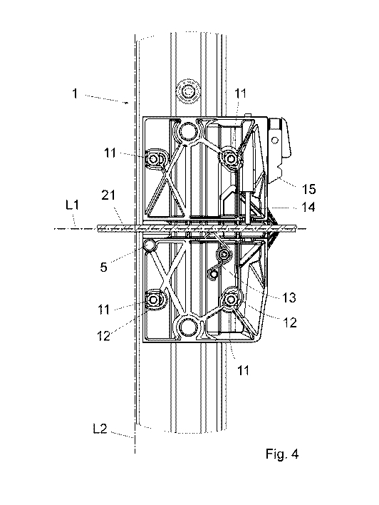
- Figure 4 corresponds to an enlarged view of detail A of Figure 3.
Detailed description of embodiments of the invention.
As shown in Figure 1, the manual ceramic cutter with adjustable set-
square comprises: an adjustable set-square (1) installed at one of the
longitudinal
extremities of the base (2) for supporting the ceramic items to be cut, and a
manually-operated cutting head (3), installed with the possibility of
displacement
along a number of longitudinal guides (4) fixed to the base (2) and vertically
spaced above the same.
By displacing the cutting head (3) along the guides (3) a longitudinal cutting
line (L1) is defined, on the ceramic item (not shown) placed on the base (2)
and
laterally supported against a support line (L2) defined by the front extremity
of the
set-square (1).
The cutter comprises a rotation axis (5) of the set-square (1) in a lateral
direction with respect to the base (2), for adjusting the perpendicularity
thereof
with respect to the cutting line (L1).
This rotation axis (5) is very close to the intersection of the cutting line
(L1)
of the cutter and the supporting line (L2) of the ceramic item against the set-
square (1).
Figure 2 shows the fixing means of the set-square (1) to the base (2) of
the cutter, made up of fixing screws (11) installed on the base (2) of the
cutter,
through some elongated holes (12) defined in the set-square (1).
In the example shown, the set-square (1) comprises four elongated holes
(12) conveniently oriented to allow a certain lateral rotation of the set-
square (1)
with respect to the rotation axis (5), and arrange it perpendicularly to the
cutting
line (L1) of the cutter, before tightening the screws (11) and the
immobilisation
thereof with respect to the base (2).
As can be seen in figure 4, corresponding to the enlarged detail (A) of
Figure 3, to correctly position the set-square (1) with respect to the base,
the
cutter comprises adjustment means of the perpendicularity of the set-square
with
respect to the cutting line (L1), represented by an elastic element (13) and
by a
manual fitting screw (14) suitable for rotating the set-square (1) in a
controlled
manner towards one side or the other of the base (2) and arranging it
perpendicularly to the cutting line (L1), referenced in Figure 2, before
tightening
the fixing screws (11).
Date Recue/Date Received 2021-12-30

CA 03145630 2021-12-30
In this embodiment, the manual fitting screw (14) and the elastic element
(13) are installed on the set-square (1) and act against a rib (21) defined in
the
base (1), which can be seen in Figure 2 and the cross-section of which has
been
included in Figure 4, and which coincides with the cutting line (L1) of the
cutter.
5 Figure 2 also shows the visual verification means of the
perpendicularity
of the set-square (1) with respect to the cutting line (L1), made up of a
longitudinal
mark (22), consisting of a groove defined in the base (2) of the cutter and
parallel
to the cutting line (L1), and of a viewer (15) fixed to the set-square (1) and
that is
arranged aligned with said longitudinal mark (22) when the set-square (1) is
located perpendicularly to the cutting line (L1).
Having sufficiently described the nature of the invention, in addition to a
preferred exemplary embodiment, it is hereby stated for the relevant purposes
that the materials, shape, size and layout of the described elements may be
modified, provided that it does not imply altering the essential features of
the
invention claimed below.
Date Recue/Date Received 2021-12-30

Representative Drawing
A single figure which represents the drawing illustrating the invention.
Administrative Status

2024-08-01:As part of the Next Generation Patents (NGP) transition, the Canadian Patents Database (CPD) now contains a more detailed Event History, which replicates the Event Log of our new back-office solution.

Please note that "Inactive:" events refers to events no longer in use in our new back-office solution.

For a clearer understanding of the status of the application/patent presented on this page, the site Disclaimer , as well as the definitions for Patent , Event History , Maintenance Fee  and Payment History  should be consulted.

Event History

Description Date
Amendment Received - Voluntary Amendment 2024-04-03
Amendment Received - Response to Examiner's Requisition 2024-04-03
Examiner's Report 2024-01-04
Inactive: Report - No QC 2024-01-02
Amendment Received - Voluntary Amendment 2023-06-08
Amendment Received - Response to Examiner's Requisition 2023-06-08
Examiner's Report 2023-02-10
Inactive: Report - No QC 2023-02-09
Inactive: Cover page published 2022-02-07
Letter sent 2022-01-26
Letter Sent 2022-01-25
Application Received - PCT 2022-01-25
Inactive: First IPC assigned 2022-01-25
Inactive: IPC assigned 2022-01-25
Request for Examination Requirements Determined Compliant 2021-12-30
Amendment Received - Voluntary Amendment 2021-12-30
All Requirements for Examination Determined Compliant 2021-12-30
National Entry Requirements Determined Compliant 2021-12-30
Application Published (Open to Public Inspection) 2021-11-04

Abandonment History

There is no abandonment history.

Maintenance Fee

The last payment was received on 2024-01-29

Note : If the full payment has not been received on or before the date indicated, a further fee may be required which may be one of the following

  • the reinstatement fee;
  • the late payment fee; or
  • additional fee to reverse deemed expiry.

Patent fees are adjusted on the 1st of January every year. The amounts above are the current amounts if received by December 31 of the current year.
Please refer to the CIPO Patent Fees web page to see all current fee amounts.

Fee History

Fee Type Anniversary Year Due Date Paid Date
MF (application, 2nd anniv.) - standard 02 2022-04-27 2021-12-30
Request for examination - standard 2024-04-29 2021-12-30
Basic national fee - standard 2021-12-30 2021-12-30
MF (application, 3rd anniv.) - standard 03 2023-04-27 2023-01-31
MF (application, 4th anniv.) - standard 04 2024-04-29 2024-01-29
Owners on Record

Note: Records showing the ownership history in alphabetical order.

Current Owners on Record
GERMANS BOADA, S.A.
Past Owners on Record
JORDI SOLER BALCELLS
Past Owners that do not appear in the "Owners on Record" listing will appear in other documentation within the application.
Documents

To view selected files, please enter reCAPTCHA code :


To view images, click a link in the Document Description column. To download the documents, select one or more checkboxes in the first column and then click the "Download Selected in PDF format (Zip Archive)" or the "Download Selected as Single PDF" button.

List of published and non-published patent-specific documents on the CPD .

If you have any difficulty accessing content, you can call the Client Service Centre at 1-866-997-1936 or send them an e-mail at CIPO Client Service Centre.


Document
Description 
Date
(yyyy-mm-dd) 
Number of pages   Size of Image (KB) 
Claims 2024-04-02 1 63
Claims 2023-06-07 2 71
Drawings 2021-12-29 5 159
Claims 2021-12-29 1 46
Abstract 2021-12-29 1 17
Description 2021-12-29 5 235
Representative drawing 2021-12-29 1 53
Claims 2021-12-30 1 45
Maintenance fee payment 2024-01-28 1 27
Amendment / response to report 2024-04-02 9 305
Courtesy - Letter Acknowledging PCT National Phase Entry 2022-01-25 1 587
Courtesy - Acknowledgement of Request for Examination 2022-01-24 1 424
Amendment / response to report 2023-06-07 13 410
Examiner requisition 2024-01-03 3 149
International search report 2021-12-29 6 203
Amendment - Abstract 2021-12-29 1 86
National entry request 2021-12-29 6 242
Voluntary amendment 2021-12-29 3 118
Amendment - Claims 2021-12-29 1 48
Examiner requisition 2023-02-09 4 196