Note: Descriptions are shown in the official language in which they were submitted.
CA 03146139 2022-01-05
WO 2021/010827 PCT/NL2020/050457
1
Pressure valve for a liquid
The present invention relates to a pressure valve for a liquid. The invention
further relates to a
device for limiting or keeping constant a flowing quantity of liquid. The
invention further relates to
manufacturing such devices.
Pressure valves comprising a housing with an inlet and an outlet and a movable
member for
closing the inlet as such are known in the form of for instance a relief valve
or pressure relief
valve. If a predetermined pressure level is reached, a spring mounted movable
member moves
away from the inlet, thereby allowing a fluid, gas or liquid, to flow through
the housing to the
outlet. These type of pressure relief valves open when a predetermined
pressure is reached.
It is a goal of the present invention, next to other goals, to provide an
improved, efficient and/or
easily adaptable pressure valve for a liquid.
This goal, amongst other goals, is met by a pressure valve for a liquid
according to appended claim
1. More specifically, this goal, amongst other goals, is met by a pressure
valve for a fluid, in
particular a liquid, comprising a housing with an inlet and an outlet for
directing the liquid from the
inlet through the housing to the outlet along a flow direction, wherein valve
further comprises a
movable member which is movable in the housing towards and away from the
outlet between a
blocked position wherein the movable member blocks the outlet and an unblocked
position
wherein the movable member is away from the outlet in a direction opposite the
flow direction.
The moveable member will be movable under the influence of the liquid flow
through the housing
and will urge the movable member towards the outlet. A relative high pressure
at the inlet, with
respect to the outlet, will thus move the movable member to the blocked
position. In the blocked
position, liquid passage through the outlet and thus the valve is blocked,
such that little, or
substantially no liquid will flow from the inlet to the outlet. The valve is
thus arranged such that
the movable member is in the unblocked position at a first (dynamic) inlet
pressure and is moved
towards the blocked position at a second inlet pressure being higher than the
first pressure.
Preferably, the movable member is arranged to move to the blocked positon upon
increasing
pressure at the inlet. A valve is thus provided which closes liquid flow with
increasing dynamic
inlet pressure.
An efficient and reliable valve is obtained if the inlet and the outlet are
substantially aligned. In
use, the liquid can then flow efficiently from the inlet to the outlet along
the flow direction. It is
then preferred that the movable member is only substantially movable along
this flow direction.
CA 03146139 2022-01-05
WO 2021/010827 PCT/NL2020/050457
2
The valve may hereto comprise a guide for guiding the movable member for
limiting movement
along the flow direction. The central axes of the inlet, the outlet and the
moving direction of the
movable member are preferably parallel, more preferably coincide. The position
of the movable
member is then efficiently regulated by the flow of liquid through the
housing. A compact
composition, which allows an efficient and controllable blocking at
(predefined) higher pressures,
is obtained if the movable member is movable between the inlet and the outlet.
The movable member is movable under the influence of the ratio of the
pressures at the inlet side
and the outlet side of the movable member. The movable member will move to the
outlet of the
housing when the pressure is higher at the inlet side of the movable member
and vice versa. In case
the pressures are substantially equal, an equilibrium is reached and the
movable member may
remain substantially stationary in the housing.
The outlet side of the movable member is defined as that part of the movable
member which faces
or is directed towards the outlet. The inlet side is then preferably located
at the other side, for
instance as seen with respect to the flow direction.
To be able to adjust the pressure at which the outlet will be blocked, the
pressure valve preferably
comprises at least one flow passage for directing liquid to the outlet side of
the movable member,
preferably from the inlet side to the outlet side. The size and/or number of
flow passages thus
determines a flow of liquid from preferably the inlet side to the outlet side
of the movable member.
The pressure at the outlet side of the movable member can thus be increased. A
higher inlet
pressure is thus required to move the movable member to the blocked position.
Preferably, the at
least one flow passage is arranged to direct a flow of liquid to the outlet
side of the movable
member separate from the movable member. The flow of liquid through the at
least one flow
passage does not typically influence the movement of the movable member.
It is further preferred if the at least one flow passage has an outlet
directed in a direction with a
component opposite the flow direction. In use, this will urge the movable
member in a direction
opposite the flow direction, i.e. away from the outlet towards the unblocked
positon. It is preferred
if the outlet of the flow passage is directed towards the movable member. A
flow of liquid from the
outlet will then be directed towards the outlet side of the movable member,
thereby urging the
movable member towards the unblocked position. Preferably, the outlet is
directed towards the
movable member in a direction having an angle of larger than 1100, more
preferably larger than
1350, with respect to the flow direction.
CA 03146139 2022-01-05
WO 2021/010827 PCT/NL2020/050457
3
Movement of the movable member can efficiently be influenced by the flow
passage if an outlet of
a flow passage is arranged adjacent the outlet, in particular when the outlet
is directed towards the
movable member in a direction with a component opposite the flow direction as
mentioned above.
Preferably, the movable member is arranged to block the flow passage outlet in
the blocked
position. The movable member then blocks both the outlet of the valve and the
flow passage outlet,
thus reducing, or even stopping, internal liquid flow in the valve in the
blocked position.
To achieve a balanced movement of the movable member along the flow direction,
it is preferred if
the one or more flow passages are arranged to direct liquid to the movable
member from a plurality
of positions located coaxially around an axis of the flow direction, more
preferably from a plurality
of positions around the outlet. It is possible to provide a slit like flow
passage outlet surrounding
the outlet and/or a plurality of outlets for instance. A corresponding number
of flow passages, may
be provided.
To effectively direct liquid from the inlet side to outlet side of the movable
member, it is preferred
if the outlet comprises a tubular member protruding into the housing, wherein
one end surface of
the tubular member is arranged to receive the movable member in the blocked
position. The end
surface for receiving the movable member then extends inwardly with respect to
the housing, for
instance a bottom thereof. A flow passage can efficiently be arranged for
directing liquid to the
outlet side of the movable member. Preferably, the flow passage is arranged to
direct liquid to a
location at or near said end surface of the tubular member.
It is hereby preferred if the opening of the flow passage outlet extends in
the end surface of the
tubular member. The flow passage may then at least partially extend through
the wall of the tubular
member. The liquid is then efficiently directed at the location of the outlet
side of the movable
member. Preferably, the end surface of the tubular member comprises a
plurality of outlets
distributed around said surface such that the outlet is surrounded by the
outlets as described above.
A reliable valve member is obtained if the movable member is at least
substantially spherical. It is
then preferred if the outlet is shaped to receive the movable member and may
be formed
complementary to the movable member. In the embodiment of the spherical
movable member, the
outlet may have a concave shape to receive the spherical movable member.
The at least substantially spherical moveable member may be held using a
suitable holding
member. In use this member may for instance guide the spherical member such
that the movable
member is only movable along the flow direction. The valve may thus further
comprise a ring
CA 03146139 2022-01-05
WO 2021/010827 PCT/NL2020/050457
4
shaped holder for holding the spherical movable member, wherein the ring
shaped holder and the
spherical movable member may be formed integrally or separately.
Additionally or alternatively, the holding member may help to direct the flow
from the inlet side to
.. the outlet side of movable member. The ring shaped member may thereto be
provided with at least
one recess in the circumferential surface for fluid passage.
To ensure a liquid flow through the outlet at lower pressures, the movable
member is biased to the
unblocked position. This may be achieved by the flow passages which direct
liquid from the inlet
side to the outlet side, thereby biasing the movable member away from the
outlet. Additionally or
alternatively a spring may be arranged for urging the movable member towards
the unblocked
position. A spring may be arranged between the movable member and the housing,
for instance at
the location of the outlet, for urging the movable member away from the
outlet. In the case of a
spherical moveable member provided with a ring shaped holder, it is preferred
if the spring
engages the ring shaped holder.
To further direct the flow of liquid in the housing, the valve preferably
further comprises a dividing
wall extending at least partially between the inlet and the outlet. The
dividing wall may for
instance divide the housing in two compartments, one containing the outlet and
the associated
movable member and one separated therefrom. For efficiently directing the
liquid flow, the
dividing wall is preferably provided with one or more flow passages. An
efficient direction of the
liquid flow is obtained if the flow passage in the dividing wall comprises a
slot which is preferably
open to the inlet side of the dividing wall.
Preferably, the dividing wall at least partially surrounds the outlet and the
movable member
associated therewith. The flow of fluid to the outlet and to the movable
member can then be
controlled by shaping the dividing wall and/or the flow passages thereof.
Preferably, the dividing
wall extends from the housing wall comprising the outlet, wherein the dividing
wall is a tubular
member extending around the outlet and the movable member. More preferably,
the dividing wall
is a cylindrical member arranged coaxially around the outlet and the movable
member. The
dividing wall preferably also extends coaxially around any tubular member
forming the outlet as
mentioned above.
It is further preferred when the tubular or cylindrical member limits movement
of the movable
member only along the flow direction, the dividing wall can then function as
guide for the movable
member, for instance in cooperation with the ring shaped holder as described
above.
CA 03146139 2022-01-05
WO 2021/010827 PCT/NL2020/050457
To prevent clogging of the pressure valve, it is preferred if the pressure
valve further comprises a
sieve at the inlet. To prevent clogging in the valve, the size or diameter of
a flow passage in the
valve is larger than the largest pore size of the sieve. Any particles
entering the valve through the
5 sieve can then flow through the valve.
The pressure valve is particularly suitable in the context of flow limiters.
In order to save water, in
particular clean drinking water, it is known to include flow regulating
devices, also referred to as
flow limiters, in water piping systems, to reduce water usage, for instance
when taking a shower or
.. bath. Such a flow limiter for limiting the flow of a fluid flowing there
through for instance
comprises a housing provided with an inlet, an outlet and a resilient plate-
like valve element which
is arranged in the housing and which is movable to and from a valve seat,
defining a flow opening
there between. Such a valve element is movable under the influence of a
pressure of the fluid
flowing there through and which is arranged to adjust the size of the through
flow opening. Higher
pressures will urge the valve element to the valve seat, thereby reducing the
through flow opening.
The flow through the outlet is then substantially constant over a pressure
range at the inlet. Such
flow limiters are described in EP 1.131.687 A and the Netherlands patent
application no. 1010592,
the contents of which are hereby incorporated by reference. These flow
regulators/limiters are
typically inserted in taps or shower heads or piping associated therewith to
keep the flow of water
substantially constant regardless of the (dynamic) water pressure.
In order to limit and/or keep constant the flow of liquid on a larger scale,
for instance in hotels,
cruise ships, agriculture and in (the petrochemical) industry, it is known to
provide a device for
limiting or regulating a quantity of fluid flowing there through, comprising a
housing which
comprises a front chamber and a rear chamber; a partition arranged in the
housing and provided
with two or more openings; and a flow limiter arranged in at least one or both
openings. Such a
device is described in WO 2015/069114, the contents of which are hereby
incorporated by
reference. By changing the number and/or types of flow limiters in the housing
of the device, the
flow of water through the device can be accurately adjusted to the specific
need.
These flow limiters are specifically designed to reduce, i.e. keep constant,
the flow of liquid at a
specific pressure range. Typically, these limiters are capable of keeping the
flow constant even at
higher pressures. At lower pressures however, the flow may not be as steady as
required or the
resistance may be too high such that the flow is too small.
CA 03146139 2022-01-05
WO 2021/010827 PCT/NL2020/050457
6
Therefore, according to a further aspect of the invention, a device for
limiting or keeping at least
substantially constant a flowing quantity of liquid is provided, comprising a
flow limiter and a
pressure valve as described above in parallel to the flow limiter. The flow
limiter is preferably
arranged to operate, i.e. keep the flow constant, from a predetermined
pressure and higher, while
the pressure valve is then arranged to pass through liquid up to the
predetermined pressure. The
valve, for instance the movable member as described above, is movable between
an unblocked
position at a first inlet pressure and is moved towards a blocked position at
a second inlet pressure
being higher than the first pressure. Preferably, the flow limiter is then
arranged to pass through
liquid at a substantially constant rate at this second pressure and higher.
Thus, at lower pressures of
liquid flow through the pressure valve, while at higher pressures the liquid
flows through the flow
limiter, while substantially no liquid flows through to the pressure valve. A
flow limiting device
which is able to provide a constant flow rate, also at lower pressures, is
thus provided.
This is in particular relevant when the backpressure at the outlet of the flow
limiting device is
relatively high, for instance in the case of a sprinkler system, for instance
as used for the irrigation
of crops. In this application, and in particular in combination with lower
inlet pressure, a
combination of a flow limiter and a pressure valve arranged to pass through
liquid only at lower
pressures, leads to an efficient flow limiting device.
The invention further relates to a method for manufacturing a pressure valve
according to the
invention, comprising the steps of:
a. defining a closing pressure for the pressure valve;
b. designing the flow passages in the pressure valve such that the movable
member moves to
the blocked position when the pressure at the inlet reaches the closing
pressure, and;
c. manufacturing said pressure valve.
As mentioned above, by adapting the number and/or sizes of the flow passages,
the shape and/or
size of the movable member, the ring shaped holder thereof, or any flow
passages in the dividing
wall, the pressure at which the pressure valve will close can be defined
efficiently.
The present invention is further illustrated by the following Figures, which
show a preferred
embodiment of the pressure valve according to the invention, and are not
intended to limit the
scope of the invention in any way, wherein:
- Figure 1 schematically shows a flow limiting device;
- Figure 2 shows a pressure valve in perspective cross-section;
- Figure 3 shows the pressure valve in exploded view; and
CA 03146139 2022-01-05
WO 2021/010827 PCT/NL2020/050457
7
- Figures 4a-c show the pressure valve in cross-section in different
working positions
Figure 1 shows a device 100 for limiting or regulating a quantity of fluid
flowing there through,
comprising a housing 100a which comprises a front chamber 103 and a rear
chamber 104; a
partition 105 arranged in the housing 100a and provided with two or more
openings 105a; and a
flow limiter 200 arranged in one or both openings. Such a device is described
in WO 2015/069114.
An inlet pipe 101 debouches in the front chamber 103 and an outlet pipe 102 is
connected to the
rear chamber 104. In this example, three flow limiters 200 as described in EP
1.131.687 A and the
Netherlands patent application no. 1010592 are provided in three of the
openings 105a of the
partition 105. The flow limiters 200 are arranged and capable of providing a
constant flow of liquid
at their exit side, substantially regardless of the input pressure at the
inlet pipe 101, provided that
this pressure is sufficiently high, for instance at least approximately 2 bar
in this example. In order
to provide a suitable flow also at lower pressures, pressure valves 1 are
arranged in the other
openings 105a. Pressure valves 1 are arranged to open at lower pressures, and
thus pass through
liquid, and to close at a higher pressure, in this example again at
approximately 2 bar. Also at
lower pressures, a substantial constant flow of liquid is thus guaranteed. A
cross-section of the
pressure valve is shown in figure 2 and an exploded view is shown in figure 3.
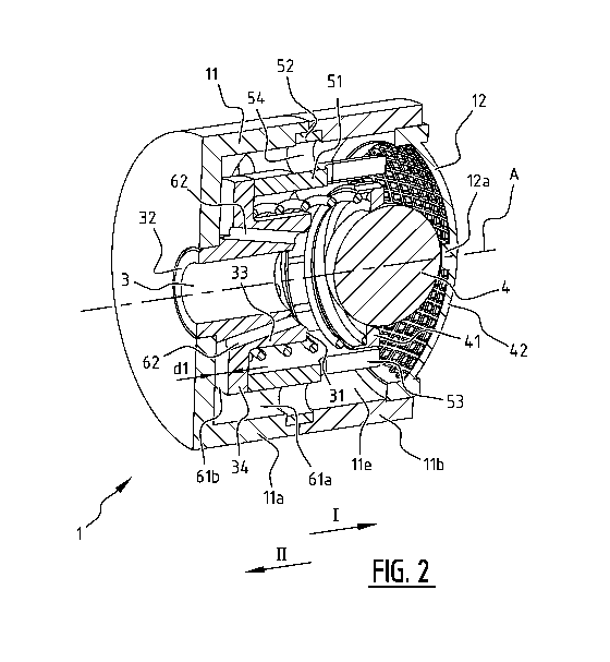
.. The pressure valve 1 comprises a housing 11 with an inlet 2 and a outlet 3,
in this example located
opposite the inlet 2 and aligned along axis A, which corresponds in this
example to the flow
direction through the pressure valve 1. The housing 11 comprises a bottom 11c,
in which the outlet
3 opens. In this example, the housing comprises two parts ha 11b. The upper
part llb is
cylindrical and the lower part 11c is provided with the bottom 11c. At the
inlet 2, a sieve 12 is
provided to prevent the inflow of larger particles.
The outlet 3 comprises a tubular member 33 of which one end 32 is arranged in
the bottom surface
11c of the valve housing 11. The other end 31 of the tubular member 31 has a
convex shape as will
be explained later for receiving a ball 4 as movable member. Flow passages 62
end in this end 31
of the tubular member 33. The tubular member 33 is further provided with a
flange 34, which in
assembled state extends at a distance dl above the bottom lld of the interior
lle of the housing
11.
A dividing member 5 having a dividing wall 51 is also arranged in the interior
lle of the housing
11. The dividing wall 51 divides the housing 11 in a circumferential outer
part, between the
dividing wall 51 and the walls 11a,b, and an inner part, enclosed by the said
dividing wall 51. The
CA 03146139 2022-01-05
WO 2021/010827 PCT/NL2020/050457
8
outlet 3, in particular the upper end 31 thereof, extends in this inner part.
Provided in the dividing
wall 51 are slots 53 which form flow passages for allowing liquid to flow from
the inlet 2 to the
outer part and vice versa. By adapting the shape and number of these slots 52,
this flow can be
adjusted.
The dividing member 5 further comprises a flange 52 in this example, which is
provided with a
plurality of openings 54 which again form flow passages for liquid. The shape
and number of these
openings 54 defines the amount of liquid which is allowed to flow to the lower
part near the
bottom lid of the housing 11. In this example, the lower part of the dividing
wall 51 engages the
flange 34 of the outlet 3. A passage 61a is thus formed between housing wall
ha and dividing wall
51, respectively flange 34. This passage 61a debouches in lower passage 61b
defined between
flange 34 and bottom lid of the housing 11. Flow passages 62, which will be
explained in greater
detail below, are connected to lower passage 61b.
For closing the outlet 3, in particular the upper part 31 thereof, a movable
member 4 in the form of
a ball is provided. The ball 4 is held in a correspondingly shaped ring 41
which at its
circumferential surface is provided with recesses 42 which again form flow
passages. A spring 43
is arranged between ball 4, in particular the ring 41, and the housing 11, in
this example the flange
34 of the outlet 3. The spring 43 urges the ball 4 towards the inlet 2, which
direction is indicated
with the arrow I. The sieve 12 is thereto provided with a receptacle 12a for
receiving the ball 4 (see
in particular figure 2).
The ball 4 and the ring 41 are in this example received within the dividing
wall 51 and the ring 41
and dividing wall 51 cooperate such that the ball 4 is only movable along one
axis A, in this
example the same axis A along which the inlet 2 and outlet 3 are aligned and
which corresponds to
the main flow direction. Recesses 42 in the ring 41, together with slots 53
define the flow of liquid
towards and from the space within the dividing wall 51.
The working of the pressure valve 1 will be further explained with reference
to figure 4a-c. In the
position as shown in figure 4a, the ball 4 extends at a distance d2 from the
outlet 3, in particular the
upper end 31 thereof. Liquid is thus allowed to flow from the inlet 2, through
the housing 11 to the
outlet 3. The main flow direction is indicated in figure 4b with the dashed
line A. Liquid flows in
the direction indicated with arrow II.
If the pressure at the inlet 2 increases, and thus the pressure at the inlet
side 4a of the ball 4, the ball
4 will be urged towards the outlet 3 in the direction of the flow direction A,
indicated with arrow
CA 03146139 2022-01-05
WO 2021/010827 PCT/NL2020/050457
9
II. It will be appreciated that the ball 4 is only movable along the axis A
and that movement in
another direction is substantially limited. If the pressure at the inlet side
4a is sufficiently high, the
ball 4 is moved completely to the outlet 3, closing or blocking said outlet 3.
This is shown in figure
4c. The movable member in the form of the ball 4 is now in the blocked
position wherein liquid
flow through the outlet is blocked. The upper end 31 of the outlet 3 is
thereto shaped
complementary to the ball 4 to allow effective blockage of the outlet 3.
When the pressure again decreases, the ball 4 may move in a direction opposite
the main flow
direction A away from the outlet 3, indicated with the arrow I, see figure 4b.
Some liquid may now
flow through the outlet 3. Thus, the higher the inlet pressure, the less
liquid flows through the valve
1. In order to adjust the pressure at which the valve 1 closes, flow passages,
for instance those
indicated with 42, 53, 54 and specifically 62, are provided to direct liquid
to the outlet side 4b of
the ball 4. The outlet side 4b is the side of the ball 4 oriented towards the
outlet 3.
The flow passages 62 are arranged to direct a flow of liquid from the inlet 2,
or the inlet side 4a of
the ball 4, towards the outlet side 4b in a direction with a component
opposite the main flow
direction. The openings in the upper part 31 are thus oriented upwards, such
that the flow is also
substantially upwardly oriented. This is indicated with the arrows. These
flows will urge the ball
member 4 in the direction indicated with I and will thus counter any movement
in the direction II.
By adjusting the amount of liquid flowing through the passages 62, the closing
pressure of the
valve 1 can be controlled.
The flow passages 62 are arranged in the tubular part 33 of the outlet 3 and
are interconnected with
the passage 61b defined between the flange 34 and the bottom lid of housing
11. This passage 61b
connects to the passage 61a defined between the dividing wall 51 and the
housing wall, in this
example the lower housing part ha. The passage 61a is delimited in this
example by flange 52, in
which openings 54 are defined. The shape and number of openings 54 thus also
influences the
amount of liquid flowing through the passages 62. The amount of liquid flowing
from the central
space within the dividing wall 51 to the circumferential outer part is inter
alia defined by the
number and shape of the slots 53 in the dividing wall 51. Also the recesses 42
influence this flow.
Thus, by adjusting the flow passages in the pressure valve 1, the closing
pressure of the valve can
be adjusted efficiently.
The present invention is not limited to the embodiment shown, but extends also
to other
embodiments falling within the scope of the appended claims. It is for
instance noted that it is
possible that the pressure valve is not provided with any spring member, as
the flow passages may
CA 03146139 2022-01-05
WO 2021/010827
PCT/NL2020/050457
be responsible for the urging back of the movable member. The pressure valve,
or generally valve,
may further be used as a fluid valve, for instance for gases.