Note: Descriptions are shown in the official language in which they were submitted.
1
WEED PICKING MODULE AND METHOD
TECHNICAL FIELD
[001] The technical field generally relates to picking implements for use
on agricultural
vehicles, and more specifically to modules and methods of optimizing weed or
crop picking
and removal with automated implements.
BACKGROUND
[002] Weeds and plants compete with crops for resources, including water,
nutrients,
and sunlight. Picking of weeds from agricultural fields is a continuous
process which
improves crop yield by removing competition for resources. Weed picking is a
labour-
intensive process and there is a desire for automation, such as by use of an
autonomous
weeding vehicle. A key performance indicator of an autonomous weeding vehicle
is its
weed picking rate. There is naturally a desire for methods and devices which
improve
weed picking rates of autonomous weeding vehicles.
SUMMARY
[003] In accordance with a first aspect, there is provided a method for
picking weeds
with an implement provided on an agricultural vehicle. The method comprises
steps to
maximize a number of weeds to be picked in a single take. The method may also
comprises steps to maximize a number of immature crop to be picked in a single
take, to
thin the field, i.e. to selectively pick young crop to allow others to grow.
The method may
comprise steps of capturing images of a field traveled by the agricultural
vehicle, the field
comprising weeds and crops. The method may comprise a step of generating a map
from
the captured images, comprising coordinates of the weeds and crops. The method
may
comprise determining, based on the coordinates of the weeds and crops, at
least one
picking location that maximizes a number of weeds to be picked in a single
take. The
method comprises determining one offset for the implement to follow for
arriving at the
optimal location. The method comprises moving the implement along the offset;
and
picking weeds at the optimal location with the implement. When the method is
used for
thinning instead of, or in addition to weeding, the offset is determined based
on the location
of immature or selected crops to be removed in a single take.
Date Recue/Date Received 2022-01-27
2
[004] In accordance with one embodiment, the implement avoids contact with the
crops
as it picks the weeds or selected immature crops.
[005] In accordance with another embodiment, moving the implement comprises a
combination of rotational and translational movements.
[006] In accordance with another embodiment, determining the offset comprises
first
selecting an anchor weed which has to be picked. In other possible
implementations, the
anchor is an immature or undesired crop that is to be removed to provide more
room for
other crops.
[007] In accordance with another embodiment, the anchor weed is selected based
on
proximity to the implement.
[008] In accordance with another embodiment, the anchor weed is selected based
on
the maximum number of weeds that may be picked in the single take while
avoiding
contact with the crops.
[009] In accordance with another embodiment, avoiding contact with the crops
comprises maintaining a minimum lateral distance between the implement and the
crops.
[0010] In accordance with another embodiment, determining the offset comprises
a step
of forming clusters of weeds comprising the anchor weed.
[0011] In accordance with another embodiment, the picking location is
determined using
a first loss function which is optimized by at least one of maximizing the
number of weeds
to be picked and avoiding the crops within a given space.
[0012] In accordance with another embodiment, the offset is determined using a
second
loss function which is optimized to center the weeds to be picked relative to
a center of
the implement.
[0013] In accordance with another embodiment, inputs to the second loss
function
comprise the coordinates of the anchor weed, the respective coordinates of
additional
weeds, and the coordinates of any crops within a footprint of the implement;
determining
the offset comprises optimizing the second loss function such that the
footprint of the
implement encompasses the coordinates of the anchor weed and at least one of
the
Date Recue/Date Received 2022-01-27
3
coordinates of the additional weeds while excluding the coordinates of any
crops;
andoutput of the second loss function comprises the offset to apply to a
current position
of the implement and an identification of the weeds picked.
[0014] In accordance with another embodiment, the step of moving the implement
along
the offset comprises first applying the offset to a current position of the
implement.
[0015] In accordance with another embodiment, the offset is further selected
from a
plurality of potential offsets based on at least one of time and implement
travel distance
required to pick all weeds at each picking location.
[0016] In accordance with another embodiment, the implement is a gripper
comprising
jaws and wherein the step of picking weeds comprises controlling the jaws of
the gripper
to pinch stems or roots of the weeds to pick them from the ground.
[0017] In accordance with another embodiment, the step of picking weeds
comprises
adjusting an opening width of the gripper based on the number of weeds to be
picked.
[0018] In accordance with another embodiment, the images are captured using at
least
one camera on the agricultural vehicle.
[0019] In accordance with another aspect, a weed picking module provided on an
agricultural vehicle, the module comprising: an agricultural implement
configured and
adapted for weed picking, the implement being translatable along three degrees
of
freedom; a controller configured to control the movement of the agricultural
implement;
and a processing module comprising: input ports for receiving coordinates of
weeds and
crops determined from images; and a non-transitory memory and a processor, the
non-
transitory memory storing the coordinates and instructions for causing the
processor to
generate an optimal location for the implement that maximizes a number of
weeds to be
gripped in a single take; and output ports for sending positioning data to the
controller, the
controller moving the implement in accordance with the optimal location and
positioning
the implement over the weeds to be gripped based on the positioning data, and
controlling
operation of the implement to pick the weeds.
[0020] In accordance with another embodiment, the implement is also rotatable
along at
least one degree of freedom.
Date Recue/Date Received 2022-01-27
4
[0021] In accordance with another embodiment, the agricultural implement is a
gripper
comprising jaws configured and adapted to pinch and retrieve stems or roots of
the weeds.
[0022] In accordance with another embodiment, one of a delta robot or a gantry
system
operatively connected to the agricultural implement, for translating the
implement along
the three axes.
[0023] In accordance with another embodiment, the controller comprises at
least one first
actuator for controlling movement of the gripper and a second actuator for
actuation of the
gripper.
[0024] In accordance with another embodiment, the memory comprises
instructions to
form clusters of weeds comprising an anchor weed.
[0025] In accordance with another embodiment, the memory stores a loss
function which
is optimized so at to maximize at least one of: number of weeds; and distance
of the
implement to the crop.
[0026] In accordance with another embodiment, the instructions stored in
memory cause
the processor to: input coordinates of the anchor weed, respective coordinates
of
additional weeds, coordinates of a crop, and a footprint of the implement to
the loss
function; optimize the loss function such that the footprint of the implement
encompasses
the coordinates of the anchor weed and at least one of the coordinates of the
additional
weeds while excluding the coordinates of the crop; and output, from the loss
function, an
offset to apply to a current position of the implement and an identification
of the weeds
picked.
[0027] All of the embodiments above can be implemented for field thinning,
instead of, or
in addition to, weeding.
[0028] Other features of advantages of the present invention will be better
understood
upon reading example embodiments thereof, with reference to the appended
drawings.
While the invention will be described in conjunction with example embodiments,
it will be
understood that it is not intended to limit the scope of the invention to such
embodiments.
On the contrary, it is intended to cover all alternatives, modifications and
equivalents as
defined in the present application.
Date Recue/Date Received 2022-01-27
5
BRIEF DESCRIPTION OF DRAWINGS
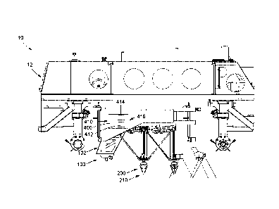
[0029] Fig. 1 is a perspective view of an example implementation of an
autonomous
weed picking vehicle having a weed picking module (not shown) mounted
underneath;
[0030] Fig. 2 is a side-view of a disassembled portion of the body of the
vehicle of Fig.
1, along with the weed picking module visible underneath;
[0031] Fig. 3 is a top-down view of the body of the vehicle and the weed
picking module
Fig. 2 placed side-by-side;
[0032] Fig. 4 is a view of an agricultural implement assembly, specifically a
gripper
assembly, that may be used in accordance with the methods described herein;
[0033] Fig. 5 is a close-up view of jaws of the gripper of Fig. 2;
[0034] Fig. 6 is an example of a 3D plot of a function representing the
gripper footprint,
for extending between two jaws of the gripper of Figs. 4 and 5;
[0035] Fig. 7 is a representation of a top view of a field in the 2D plane
with weeds
identified as x-shaped and crops identified as circles, and an anchor weed
identified as an
x surrounded by a circle;
[0036] Fig. 8 is an example of an optimized gripper footprint in accordance
with the
methods described herein, showing an optimum solution of the field of Fig. 6
for maximum
weed picking in a single take while respecting the constraint of not picking
crops; and
[0037] Fig. 9 is an example flow chart of possible steps carried out to pick
in a single
take a maximum number of weeds at an optimal location, in accordance with one
implementation.
Date Recue/Date Received 2022-01-27
6
DETAILED DESCRIPTION
[0038] Broadly described, the picking module can be used on or with an
agricultural
vehicle, such as an autonomous weeding machine, capable of navigating farm
fields while
identifying weeds and pulling them using a controllable implement, such as a
robot gripper.
The module focuses on picking and removing weeds or other undesired plant
growing
close to the crop where other means of weeding are not effective and manual
labor is
employed. The weeds are picked by physically gripping them and pulling them
from the
earth and then discarding them on the ground.
[0039] With reference to Fig. 1 and in accordance with one implementation,
there is
shown an agricultural vehicle 10 for picking weeds or for thinning crops from
an agricultural
field. The vehicle 10 shown therein is configured to travel along lanes in an
agricultural
field, over longitudinal sections of soil, to pick, remove and dispose of
weeds. In possible
implementations, the vehicle is an autonomous vehicle, comprising cameras,
sensors and
processors to control electric motors and wheels connected to the motor(s). In
other
possible implementations, the vehicle can a tractor or other agricultural
vehicle, controller
by a driver. The crops can be of different types, including vegetable crops,
such as
lettuces, carrots, and onions.
[0040] With reference to Figs. 2 and 3, some components of the autonomous
vehicle 10
are shown disassembled. The components shown include a frame, or chassis, 12
and a
picking module 100 mounted thereon, including an agricultural implement 200
for picking
weeds, for weeding the field. The picking module can be affixed underneath the
vehicle or
attached to one of its sides and tracked. The agricultural implement may also
be
configured and adapted for thinning the field, where in this case, selected
immature crops
are removed to provide enough room to allow stronger crops to grow. As such,
the picking
module can also be referred to a weeding and/or to a thinning module. In
possible
implementations, such as the one illustrated, the agricultural implement 200
can be a
gripper 210. In the illustrated implementation, there is provided three
grippers 210a, 210b,
210c, each capable of weed picking and removal in a predefined zone underneath
the
vehicle. Alternatively, there may be provided a single gripper for serving the
entire zone,
or multiple grippers serving overlapping zones. In one implementation, it is
preferable that
the grippers are configured to not only grab weeds from the above-ground
portion of the
Date Recue/Date Received 2022-01-27
7
weed (e.g., the leaves), but to pinch the roots of the weeds and fully
retrieve them from
the ground. Picking at the root of the weed or plant may reduce the likelihood
of the weed
regrowing, whether in place or displaced elsewhere. In the illustrated
implementation, the
grippers 210 are installed at an end of a delta robot 150, with the delta
robot 150 providing
translational and rotational movement, as will be explained in more detail. In
a possible
implementation, and with reference to the example illustrated in Fig. 4, the
gripper may
comprise two jaws or plates 212, which can be controlled such that they can be
spaced
apart or brought together to pinch the weeds or plants, such as the stems,
preferably near
or within the soil, close to the roots. As will be explained in more detail,
the gripper can be
moved along a plane parallel to the soil and rotated along a vertical axis.
[0041] The picking module 100 may comprise frame 102 onto which the grippers
210
and other parts can be mounted, as well as a processing module 400 comprising
a
processor 414 and non-transitory memory 412 for storing and carrying out
computer
instructions (see Fig. 10). The frame 102 can include structural members, such
as tubes,
and side plates to protect the components of the modules from dust, mud and/or
water.
The frame 102 may also include connecting members (not shown) adapted to
connect to
the frame 12 of the agricultural vehicle 10. In possible implementations, the
weed picking
module can be a distinct, independent module, mountable onto different types
of
agricultural vehicles, which may or not be autonomous vehicles. In other
implementations,
the weed picking module can be provided as part of and integral to the
vehicle, such as in
the illustrated implementation. The picking module may also be attached and
tracked
behind a tractor or other similar vehicle.
[0042] The picking module 100 additionally may include cameras 220 mounted
thereon
for identifying weeds, extra or immature plants and crops in the agricultural
field. The
cameras 220 may be coupled to lights mounted in proximity thereof for
illuminating the
field of vision of the cameras 220, providing improved images. In the
illustrated
implementation as shown in Figs. 2 to 5, there is shown a weed picking module
100 with
cameras 220 mounted onto the frame 102 of the weed picking module 100.
Alternatively,
the cameras 220 may be mounted proximate to the gripper 210, such as on the
end of the
delta robot 150. In one implementation, the cameras 220 may instead, or
additionally, be
mounted onto the vehicle 10. The lights coupled to the cameras 220 may also be
mounted
either onto the weed picking module 100, or the vehicle 10.
Date Recue/Date Received 2022-01-27
8
[0043] With the implementation shown, when the autonomous weeding vehicle 10
passes in an agricultural field, the picking module 100 is activated. Once the
picking
module 100 is activated, the cameras 220 begin capturing images of the field.
In one
implementation, the cameras 220 are coupled to a transceiver module for
transmitting
images to a remote site where an artificial intelligence (Al) system
identifies weeds and
crops. In one implementation, the images transmitted by the cameras 220 are
interpreted
by an operator at the remote site who marks crops and weeds, and also
optionally
immature crops that are to be removed for thinning. The cameras 220 may
transmit the
images through any wireless communication system to the remote site. In yet
other
implementations, the Al module and image analysis can be conducted locally, in
a
processing device provided on the vehicle and in communication with a
controller
controlling the weed picking implement.
[0044] According to the images generated and marked with respect to weeds and
crops,
and possibly other plants, such as immature crops, a map 500 may be generated
identifying the coordinates of weeds 520 and crops 510 in the area captured by
the images
(see Fig. 7). The weeds and crops appearing in the images captured by the
image sensors
or cameras can be first identified by pixel analysis. Their coordinates can
then be
determined. For example, a Euclidean map can be generated, using Simultaneous
Localization and Mapping (SLAM) algorithms, which allows building a map and
localizing
the vehicle and/or picking modules at the same time. In a possible
implementation, pixels
of the map 500 can be classified as weed, crop or other, such as other types
of plants or
immature, week crops, and this classification can be used to determine a
center coordinate
of the plants, such as weeds and crops. In possible implementations, different
types of
weeds and plants could be detected, and the weed picking method could be
adapted
accordingly. In a possible implementation, machine learning models, such as
deep neural
network models, can be used to differentiate between weeds, immature crops and
desired
crops.
[0045] In one implementation, the map 500 may instead, or in addition to the
cameras
of the weeding module 100, be provided by another image capture system such as
a
satellite image. As the vehicle travels through the agricultural field, the
map 500 may be
continuously updated with images captured by the cameras. Additionally, a
speed of the
vehicle may be aligned with the camera capture rate and the processor. The
speed of the
vehicle may be calibrated so that the vehicle moves through the field at a
rate that allows
Date Recue/Date Received 2022-01-27
9
for the cameras and the processor to capture and process images, and to then
effect weed
picking by the gripper 210.
[0046] The processing module 400 is configured to receive inputs, such as the
map 500
or the weed and crop coordinates, process the inputs, and output data for
controlling the
gripper. For example, the map 500 or map data may include coordinates of weeds
520
and crops 510. The coordinates can be provided or accessed through input ports
410 to
the memory 412 and the processor 414, the processor 414 generating an offset
for the
gripper 210 to move and rotate to, based on the received coordinates, and
sending the
offset information via output ports 416 to a controller for controlling the
gripper 210. The
controller controls the movement of the grippers 210 based on the coordinates
of the
weeds and crops. In one implementation, the controller comprises a first
actuator for
controlling movement of the gripper and a second actuator for actuation of the
jaws
(opening and closing) of the gripper. In one implementation, the at least
first actuator
comprises four actuators, each one corresponding to translation along the x, y
and z axes,
as well as rotation around the z axis. In the illustrated implementation, the
weed picking
module 100 is installed underneath the autonomous weeding vehicle 10. In one
implementation, the weed picking module 100 may be installed in a front, a
side, or a rear
portion of the vehicle 10 for carrying out weed picking. In the illustrated
implementation,
the grippers 210 of the weed picking module 100 are moveable via three
mechanical arms
which allow for translational motion of the grippers along three degrees of
freedom, also
known as a delta robot configuration. The grippers 210 are further rotatable
along a vertical
axis of the autonomous weeding vehicle 10. The grippers 210 thus have four
degrees of
freedom, three translational and one rotational. Alternatively, the grippers
210 may have
fewer or greater degrees of freedom depending on design requirements, or they
may use
a movement configuration different to a delta robot configuration. For
example, they may
instead use a gantry system whereby the gripper is translatable along three
axes. In
preferred implementations, the gripper is translated along 3 degrees of
freedom (DOF: x,
y, z) and rotated about the z axis, allowing controlling the gripper with 4
DOF. While
providing better results, rotation of the gripper 210 may be optional, and it
can be
considered only to translate the gripper 210 in accordance with the optimal
location/offset
that will maximize the number of weeds 530 that can be picked in a single
take, while
avoiding the crops 510. For thinning purpose, the offset can be calculated to
maximize the
number of immature crops to remove near the desired, stronger crops.
Date Recue/Date Received 2022-01-27
10
[0047] The processing module 400 is thus configured to maximize a weed picking
rate
by maximizing the number of weeds 520 to be picked in a single take. A single
take, or
picking event, involves deployment of the gripper 210 from a first position,
such as
proximate to the frame 102 of the picking module 100, to a second position
proximate the
ground for weed or immature crop picking. The map 500 produced based on the
images
is processed, and an anchor weed 530 is selected (see Fig. 7). When identified
objects,
such as weeds 530 and crops 510, in the map 500 coincide with the working area
of the
picking module, the weed 530 can be grabbed: at that point an optimization
search is
conducted to determine the next optimal picking location to maximize the
number of weeds
picked in a single take. The picking location can generally correspond to the
center of the
implement or gripper. It will be noted that the field of view of the camera
220 does not
need to correspond to the working area of the agricultural implement or
gripper 210. What
is needed is that the coordinates of the weeds 520 be contained within the
working area
of the implement. It will be also noted that, since the vehicle 10 is in
motion, the working
area continuously changes as the vehicle 10 advances in the field, which is
taken into
account by the processing module 400.
[0048] The anchor weed 530 corresponds to a weed that must be picked in a weed
picking event. The anchor weed 530 may, in one implementation, be the closest
weed to
the gripper 210 (selection based on proximity to the gripper). In one
implementation, the
anchor weed 530 may instead be selected based on other parameters, such as the
number of weeds 520 in a cluster of weeds, for example allowing for a maximum
number
of weeds 520 to be picked in a single take. The cluster of weeds defines a
group of weeds
520 that are removeable in a single take and includes the anchor weed 530. In
this
implementation, the memory 412 of the processing module 400 may include
instructions
for the processor 414 to form multiple clusters of weeds, then resolve and
compare
solutions for each cluster to find which solution allows for the greatest
number of weeds
520 to be picked in a single take. Al clustering models can be used to form
the clusters of
weeds, such as k-means models. Alternate clustering methods can also be used,
such as
simpler Euclidian distance-based methods. Since several clusters are likely to
be formed,
the system can choose the cluster which optimizes a "loss function".
Parameters inputted
in the clustering loss function can include the number of weeds in a given
cluster, the
presence of a crop 510, the distance of the cluster from the crop 510 and
whether the
shape of the loss function is similar to the footprint of the gripper 210. The
loss function
Date Recue/Date Received 2022-01-27
11
can be optimized at least one of maximizing the number of weeds to be picked
and
avoiding the crops within a given space. The space can be a 3D space or zone,
such as
the one represented by Fig. 6.
[0049] The anchor weed 530 may also be selected based on constraints, for
example
being selected to avoid gripper 210 contact with the crop 510. In possible
implementations,
the processor 414 may find that an anchor weed 530 cannot be picked while
respecting
the constraints, such as crop 510 avoidance. The anchor weed 530 may therefore
need
to be changed to allow for a solution which respects the constraints. In one
implementation, the constraints may comprise a maximum or minimum weed
distance
from a crop 510. A maximum weed distance from a crop 510 may be chosen to
allow for
weeds 520 that are determined to be too far to be competing with crops 510 to
be left in
the field. A minimum weed distance from a crop 510 may be chosen to reduce or
eliminate
the likelihood of contact of the crop 510 with the gripper. In one
implementation, the
constraints may comprise a maximum or minimum gripper distance from the crop
510.
Similar to the weed distance previously mentioned, a maximum gripper distance
may allow
the gripper to ignore weeds too far away, while a minimum gripper distance may
reduce
or eliminate the likelihood of contact with the crop 510, to avoid damaging
the crop while
removing weeds. The minimum and maximum distances may be one of lateral
distance,
vertical distance, or a combination of the two to ensure that sufficient
distance separates
the gripper 210 from the crop 510.
[0050] Picking the maximum number of weeds 520 per take involves, firstly,
processing
of the map 500 with respect to the anchor weed 530. The footprint of the
gripper 210 may,
in effect, be modelled. In a possible implementation, it can be modeled as a
function in a
3D space, whereby the 3D space has an x-axis, a y-axis, and a z-axis. The
distance
between gripper jaws may be the width of the 3D space, the length of the jaws
may be the
length of the 3D space, while the grippable height, extending from a bottom
end of the
gripper jaw to a top end of the gripper jaw, may be the height of the 3D
space. For example,
and with additional reference to Figs. 5 and 6, the gripper footprint may be
modelled in the
3D space along an x and y plane using the following function:
px = x ¨ xc
Py = Y ¨ Yc
Date Recue/Date Received 2022-01-27
12
2 2
px \ py
z(x,y) = max ((-1 , (¨) )
if z 1
[0051] Where z defines a point in the 3D space. 1 defines the length of the
gripper/a jaw
(i.e., the length of the 3D space), w defines the space between the jaws
(i.e., width of the
.. 3D space), x, and it, define center points of the gripper in the x and y
plane, and x and y
represent coordinates in the x and y plane. With reference to Fig. 6, z(x,y)
has been plotted
for illustrative purposes showing the footprint according to one embodiment
using example
values of 20 and 40 for 1 and w, respectively. The point z(x,y) is unitless,
so long as both
the numerator and the denominator use the same units. In the above example and
as
illustrated in Fig. 6, the point z(x,y) is within the gripper's footprint if
z(x,y) is equal to, or
smaller than, 1. Alternatively, other values may be selected for z(x,y) based
on specific
values of gripper length and width. Additionally, in the above example land
ware constant
values. However, w may instead be a variable value. This may be the case where
the jaws
are selectively operated to different widths between the jaws (e.g., fully
open, or partially
open).
[0052] In possible implementations, given that the gripper footprint can be
further rotated
around the z axis, the gripper footprint may fully be modelled using the
following functions
accounting for rotation along the z axis, in addition to positioning along the
x and y planes:
p, = cos(0)px ¨ sin(0) py
pyr = sin(0) px + cos (0)py
n 2 p r2
z(x,y) = max (( )
'
/ w
[0053] With the gripper footprint fully modelled, the first loss function (or
cost function)
which respects the constraints (e.g., crop avoidance) and the objectives of
the weed
picking device (e.g., maximum number of weeds per take), is then solved with
respect to
the picking space or zone defined above. As an example, the first loss
function may be of
the following form:
argmax(f(c, w))
Date Recue/Date Received 2022-01-27
13
[0054] Where c is the number of crops and w is the number of weeds. For
example, the
crops 510 may each have a negative value (e.g., -3), while the weeds 520 may
have a
positive value (e.g., +1). The specific values may be selected by the
operator. The function
may be of the simplest form comprising the sum of c and w. The function may
then be
solved in the space and optimized. The processor optimizes for the value of
the function
with respect to the number of weeds 520 while respecting the constraints so
that a
maximum value is obtained. The optimized solution of the function, having the
maximum
value, represents a picking location where the maximum number of weeds 520 may
be
picked. In one implementation, even after applying a large penalty to a
constraint, it is
possible that the solution will still not respect a constraint. For example,
it may be the case
that five weeds 520 (with a value of +1 each) and one crop 510 (with a value
of -3 each)
are within the footprint of the gripper 210, having a sum of +2 which may
suggest that the
solution is optimal. Since this solution would also pick the one crop 510
along with the five
weeds 520, it may not be acceptable. Accordingly, it may be desired to
explicitly check a
constraint to ensure that it is respected or to define the constraint with a
very high value
that cannot be overcome in any practical scenario.
[0055] In a next step, once the map 500 has been processed and the picking
location
selected in view of the optimized function, the positioning of the gripper 210
may be
controlled accordingly. In a possible implementation, a second loss function
may,
therefore, additionally include optimization for positioning of the gripper:
argmin(fxgygeg (Pw, Põ, xg,Yg, Os))
[0056] Where Pw is the xy coordinates of the weeds (including the anchor weed
530),
Pcr is the xy coordinates of the crops, xg is the offset of the x coordinate
of the gripper, yg
is the offset of the y coordinate of the gripper, and eg is the offset of the
orientation of the
gripper. The function is optimized by looking for the minimal values of x,,y,
and e with
respect to the coordinates of the weeds 520 and the crops 510. That is, there
is an offset
that the gripper 210 must travel in the x and y directions and along the e
axis to arrive at
the picking location which allows the gripper 210 to respect all the
constraints, while
maximizing the number of weeds 520 picked in a single take. The solution that
results in
.. the minimal value of the function is the optimized solution. The optimized
solution
comprises both an optimal offset, whereby the gripper moves by the offset
amounts in the
x and y directions and the e axis, and an optimal weed picking location, where
the greatest
Date Recue/Date Received 2022-01-27
14
number of weeds may be picked in a single take. In one implementation, the
optimal offset
may instead be carried out in only one axis, only two axes or any other
variation.
Optimizing the second loss function allows centering the weeds to be picked
relative to
the center of the implement.
[0057] As an example, the second loss function ensures that that the gripper
encompasses the coordinates of the anchor weed 530, at least one additional
weed, while
avoiding the crop 510. The processing module 400 may then control the gripper
210 to
pick the weeds 520 in the optimal location, and then stores the information
about the
picked weeds 520 in the memory, so that the map 500 may be updated as the
vehicle 10
moves through an agricultural field.
[0058] The second loss function may, in one implementation, be defined
according to
the following:
Pw
Wcost z(p)
CZ(p)
C cost ______________________________________
Where:
if if
Tcost = wcost
if Cost < 1,Tcost = a ' Wcost
[0059] Where Wcost is the cost with respect to the weeds, Cost is the cost
with respect
to the crops, Tcost is the total cost, a is a number greater than 1, and Nu is
the number of
crops considered by the gripper. Nu has a minimum value of 1, since the
gripper considers
at least one crop when deciding which weeds to pick. In resolving the above
functions,
only those weeds and crops falling in the gripper footprint are considered
(where z1).
Any neighboring weeds and crops may be ignored. Per the above, where the cost
for crops
Cost is equal to or greater than 1, there are no crops in the gripper
footprint and the
constraint of crop avoidance is respected. In this case, the total cost Tcost
is equal to the
cost for weeds W
cost= If Cost is smaller than 1, however, the crop is inside the gripper
Date Recue/Date Received 2022-01-27
15
footprint and would be grabbed. Accordingly, this would not respect the crop
avoidance
constraint and the solution would not be acceptable. In such a case, Wõst is
multiplied by
an arbitrarily large number a to return a large loss.
[0060] The optimized solution may be found through any number of optimization
tools.
In one implementation, optimization may be achieved through Particle Swarm
Optimization (PSO). PSO optimizes a function by iteratively improving a
potential solution
with regards to given variables so as to obtain the best solution. Other
optimization tools
may equally be used, such as constrained optimization by linear approximation
(COBYLA). In accordance with the above, the second loss function finds an
optimal
location for the gripper to maximize the number of weeds while respecting
constraints in
a first step. In a next step, the second loss function finds an optimal
offset, using both
translational and rotational motion, for the gripper to move along and arrive
at the optimal
location for picking the weeds. In one implementation, it may be desired to
not optimise a
solution. For example, the first loss function alone may be sufficient without
consideration
of the second loss function. In such a case, the only constraint to be
considered may be,
for example, whether there is a crop 510 inside the footprint of the gripper
210. The first
loss function may accordingly be resolved while accounting only for crop
avoidance, so
that no optimisation is carried out for either maximizing the number of weeds
or for finding
an optimal offset to the optimal location. In one implementation, constraints
may be shared
between the optimal location and the optimal offset, for example to ensure
that the gripper
maintains a minimum distance to the crops as it moves in accordance with the
optimal
offset to an optimal location for weed picking.
[0061] The specific optimization tool, such as PSO or COBYLA, may be selected
based
on case-specific data or through comparison. In one implementation, for
example, it was
found that PSO resulted in a higher rate of weed picking, while also having a
slightly higher
rate of failure which was acceptable in the present case:
Date Recue/Date Received 2022-01-27
16
Table 1
1000 samples fail rate pick-able fails average weed
average time
picked per pick
PSO 0.5% 5 2.8E7 0,03469653968s
COBYLA 01% 1 2.770 D.03747627375
1000 sampie5 ()
PSO OL1% 1 2.910 0.03183686363s
COBYLA 0,1% 1 2753 D.03927579847s
10000 samptes
PSO 0,70% [unknown 2.9060 D.0322792743025
COBYLA 010% unknown 2.7572 D.038344851335
[0062] Table 1 shows a comparison of two optimization tools, PSO and COBYLA,
in one
example based on 1,000 samples, a second example of 1,000 samples, and a third
example of 10,000 samples, each sample corresponding to the number of times
the
algorithm was run based on given initialization conditions. The above is only
provided for
illustrative purposes. Other optimization tools may equally be preferred
generally based
on a compromise between accuracy and computational requirements.
[0063] In one implementation, the gripper 210 moves to the anchor weed 530
first, then
determines the rotational and translational movement required to maximize the
number of
weeds in the take, while also grabbing the anchor weed 530. In one
implementation, there
may be other constraints/variables which the function can consider. For
example, the
function may additionally consider distance to the crop when determining an
optimal offset
or when determining the positioning of the gripper. In one implementation, the
function
may be capable of considering other factors, including time required to reach
the weeds,
where, for example, the minimum translation (implement travel distance) and
rotation as
defined in the second loss function do not result in a minimized or optimized
gripper travel
time.
[0064] With reference to Figs. 7 and 8, there is provided an example
implementation of
the above-described method. In Fig. 7, an exemplary field has been mapped
following
Date Recue/Date Received 2022-01-27
17
image capture and processing. In the map 500 are visible weeds 520 (x-shaped)
and crops
510 (filled circles), as well as the anchor weed 530 (x-shaped surrounded by a
circle). The
second loss function can be used to determine the optimum solution, whereby
the
maximum number of weeds are picked in a single take while minimizing movement
of the
gripper. The positioning of the gripper is illustrated in Fig. 8, with the
gripper footprint
shown as a rectangle. The rectangle, or gripper footprint, represents the
distance between
the two jaws of the gripper and their length, such that any objects in that
space can be
grabbed by the gripper when the jaws close. The gripper is positioned to the
optimal
location and deployed so that it may pick the weeds in the gripper footprint.
More
specifically, the gripper is moved to the calculated position, which may
correspond to the
anchor weed coordinate plus an offset added to be able to grasp the additional
neighbouring weeds. Moving the gripper may entail translating the picker along
in x, y and
z, and preferably also rotating the gripper. The gripper is then lowered, the
jaws are
opened (the order these steps can be inverted), the weeds are pinched, and the
gripper
is raised, and moved away from the crops, to dispose of the weeds. The memory
then
stores a parameter indicating that the weeds were picked, updates the map 500
to remove
the picked weeds, and moves onto another position in the map 500 by choosing
another
anchor weed. This exercise is repeated until either no more weeds are left
within the
working area of the gripper, or that no more solutions exist which respect the
constraints
set by the operator. That is to say, if a weed cannot be picked while, for
example, avoiding
contact with a crop 510, due to proximity to the crop 510, then that weed may
be left until
either a constraint is softened or an operator sends overriding instructions.
[0065] With reference to Fig. 9, there is provided an example flow chart based
on the
embodiment disclosed herein. In a first step, images are captured from a
camera (or
cameras), mounted onto the autonomous vehicle. In a second step, the
processing
module 400 of the autonomous vehicle then processes the images to generate a
map 500
of the captured area which comprises coordinates of the weeds and crops. In a
third step,
constraints may be set including crop avoidance as well as the variables to
optimize for in
the second loss function, such as maximizing the number of weeds and
minimizing gripper
displacement. In a fourth to sixth step, an optimization tool is used to
iteratively generate
solutions and arrive at an optimum solution which respects the constraints
previously set.
Once the solution has been found for an optimal offset and a maximum number of
weeds
Date Recue/Date Received 2022-01-27
18
picked per take, the gripper is moved along the optimal offset and deployed at
an optimal
location whereby the maximum number of weeds are picked in a single take.
[0066] As disclosed, it is possible that a solution cannot be found for
picking of a weed,
even after softening constraints or changing the anchor weed. In such cases,
an operator
.. may decide to either ignore the weed or to override the constraints, for
example allowing
the gripper to make contact with a crop while picking the weed. Additionally,
although we
have treated the 3D space of the jaws as a constant space, it may additionally
be modified.
For example, the distance between the two jaws may be modified by moving the
jaws
closer together or further apart. This may be useful in cases where a solution
cannot be
found while respecting constraints with a larger space between the jaws, where
a smaller
distance allows a solution to be obtained.
[0067] Although reference and examples have been made to weed removal in
accordance with one embodiment of the present disclosure, it is equally
envisaged that
other uses may be possible. For example, the agricultural implement may,
instead of
removing weeds from a field, remove extra or immature crops. Crop thinning is
the process
of removing young crops from a field to make space for other, stronger crops.
For example,
carrots are often planted in a row in a field. It is sometimes necessary to
remove some
carrots from the row to allow other carrots to grow to full size. It may also
be necessary to
remove carrots in areas where growth has been less than desired, due to poor
sunlight or
other factors. The removed carrots may then be replanted elsewhere or disposed
of.
Accordingly, instead of identifying and removing weeds from a field, the
present disclosure
may instead be directed to identifying and removing immature or selected
crops, such as
young carrots.
Date Recue/Date Received 2022-01-27