Language selection

Search

Patent 3146890 Summary

Third-party information liability

Some of the information on this Web page has been provided by external sources. The Government of Canada is not responsible for the accuracy, reliability or currency of the information supplied by external sources. Users wishing to rely upon this information should consult directly with the source of the information. Content provided by external sources is not subject to official languages, privacy and accessibility requirements.

Claims and Abstract availability

Any discrepancies in the text and image of the Claims and Abstract are due to differing posting times. Text of the Claims and Abstract are posted:

  • At the time the application is open to public inspection;
  • At the time of issue of the patent (grant).
(12) Patent Application: (11) CA 3146890
(54) English Title: HYDRAULIC DRIVE TRAIN FOR A FRAC PUMP
(54) French Title: TRAIN D'ENTRAINEMENT HYDRAULIQUE POUR POMPE DE FRACTURATION
Status: Application Compliant
Bibliographic Data
(51) International Patent Classification (IPC):
  • F04B 23/06 (2006.01)
  • E21B 43/20 (2006.01)
  • E21B 43/26 (2006.01)
(72) Inventors :
  • BAYYOUK, JACOB A. (United States of America)
  • WAGNER, BRYAN C. (United States of America)
  • CLARK, WESLEY P. (United States of America)
(73) Owners :
  • SPM OIL & GAS INC.
(71) Applicants :
  • SPM OIL & GAS INC. (United States of America)
(74) Agent: SMART & BIGGAR LP
(74) Associate agent:
(45) Issued:
(86) PCT Filing Date: 2020-07-28
(87) Open to Public Inspection: 2021-02-18
Availability of licence: N/A
Dedicated to the Public: N/A
(25) Language of filing: English

Patent Cooperation Treaty (PCT): Yes
(86) PCT Filing Number: PCT/US2020/043913
(87) International Publication Number: WO 2021030048
(85) National Entry: 2022-02-03

(30) Application Priority Data:
Application No. Country/Territory Date
62/886,263 (United States of America) 2019-08-13

Abstracts

English Abstract

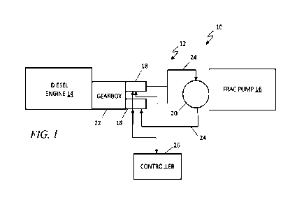
A hydraulic drive system is employed to transfer energy generated by a diesel engine to a frac pump. The hydraulic drive system includes a gearbox comprising a plurality of gears being coupled to and driven to produce rotational movement by the diesel engine, at least one hydraulic pump coupled to at least one gear of the gearbox, and operable to, driven by the rotational movement of the at least one gear of the gearbox, force a fluid at high pressure into at least one high-pressure fluid conduit, and at least one hydraulic motor coupled to the at least one high-pressure fluid conduit to receive the high-pressure fluid, and operable to transform energy in the high-pressure fluid to a rotational movement, which is used to power and drive a plurality of plungers in the frac pump.


French Abstract

La présente invention concerne un système d'entraînement hydraulique qui est employé pour transférer de l'énergie générée par un moteur diesel à une pompe de fracturation. Le système d'entraînement hydraulique comprend une boîte de vitesses comprenant une pluralité d'engrenages accouplés au moteur diesel et entraînés pour produire un mouvement de rotation par celui-ci, au moins une pompe hydraulique accouplée à au moins un engrenage de la boîte de vitesses et pouvant fonctionner de façon à, entraînée par le mouvement de rotation du au moins un engrenage de la boîte de vitesses, forcer un fluide à haute pression dans au moins un conduit de fluide à haute pression et au moins un moteur hydraulique accouplé au(x) conduit(s) de fluide à haute pression pour recevoir le fluide à haute pression et pouvant fonctionner pour transformer l'énergie dans le fluide à haute pression en un mouvement de rotation, qui est utilisé pour alimenter et entraîner une pluralité de plongeurs dans la pompe de fracturation.

Claims

Note: Claims are shown in the official language in which they were submitted.


WHAT IS CLAIMED IS:
1. A hydraulic drive system transferring energy generated by a diesel
engine to a frac pump,
comprising:
a gearbox comprising a plurality of gears being coupled to and driven to
produce rotational
movement by the diesel engine;
at least one hydraulic pump coupled to at least one gear of the gearbox, and
operable to, driven by
the rotational movement of the at least one gear of the gearbox, force a fluid
at high pressure into at least
one high-pressure fluid conduit; and
at least one hydraulic motor coupled to the at least one high-pressure fluid
conduit to receive the
high-pressure fluid, and operable to transform energy in the high-pressure
fluid to a rotational movement,
which is used to power and drive a plurality of plungers in the frac pump.
2. The hydraulic drive system of claim 1, further comprising at least one
return fluid conduit
operable to conduct fluid from the at least one hydraulic motor back to the at
least one hydraulic pump.
3. The hydraulic drive system of claim 1, further comprising at least one
valve in the at least
one high-pressure fluid conduit adapted to regulate flow and pressure of the
fluid therein.
4. The hydraulic drive system of claim 1, further comprising at least one
valve in the at least
one return fluid conduit adapted to regulate flow and pressure of the fluid
therein.
5. The hydraulic drive system of claim 1, further comprising at least one
accumulator
adapted to collect fluid from the hydraulic pump and control fluid pressure in
the hydraulic conduits.
6. The hydraulic drive system of claim 1, wherein the at least one
hydraulic pump
comprises a plurality of hydraulic pumps coupled to the diesel engine in a
piggyback configuration.
7. The hydraulic drive system of claitn 1, wherein the at least one
hydraulic motor
comprises a plurality of hydraulic motors coupled to the frac pump in a
piggyback configuration.
8. The hydraulic drive system of claim 1, further comprising a closed loop
controller
coupled to the at least one hydraulic pump configured to receive at least one
measured speed and rate
from the at least one hydraulic pump and generating a control signal for
optimal operation of the
hydraulic drive system.

9. The hydraulic drive system of claim 8, wherein the controller comprises
a proportional-
integral-derivative controller.
10. A hydraulic drive system transfening energy generated by a prime mover
to a frac pump,
comprising:
a gearbox comprising a plurality of gears being coupled to and driven to
produce rotational
movement by the prime mover;
at least one hydraulic pump coupled to at least one gear of the gearbox, and
operable to, driven by
the rotational movement of the at least one gear of the gearbox, force a fluid
at high pressure into at least
one high-pressure fluid conduit;
at least one hydraulic motor coupled to the at least one high-pressure fluid
conduit to receive the
high-pressure fluid, and operable to transform energy in the high-pressure
fluid to a rotational movement,
which is used to power and drive a plurality of plungers in the frac pump; and
a controller coupled to the at least one hydraulic pump configured to receive
at least one
measured speed from the at least one hydraulic pump and generating a control
signal for optimal
operation of the hydraulic drive system.
11. The hydraulic drive system of claim 10, further comprising at least one
return fluid
conduit operable to conduct fluid from the at least one hydraulic motor back
to the at least one hydraulic
pump.
12. The hydraulic drive system of claim 10, further comprising at least one
valve in the at
least one high-pressure fluid conduit adapted to regulate flow and pressure of
the fluid therein.
13. The hydraulic drive system of claim 10, further comprising at least one
valve in the at
least one return fluid conduit adapted to regulate flow and pressure of the
fluid therein.
14. The hydraulic drive system of claim 10, further comprising at least one
accumulator
adapted to collect fluid from the hydraulic pump and control fluid pressure in
the hydraulic conduits.
15. The hydraulic drive system of claim 10, wherein the at least one
hydraulic pump
comprises a plurality of hydraulic pumps coupled to the prime mover in a
piggyback configuration.
6

16. The hydraulic drive system of claim 10, wherein the at least one
hydraulic motor
comprises a plurality of hydraulic motors coupled to the frac pump in a
piggyback configuration.
17. A hydraulic drive system transfening energy generated by a prime mover
to a frac pump,
comprising:
at least one hydraulic pump coupled to the prime mover, and operable to,
driven by the prime
mover, force a fluid at high pressure into at least one high-pressure fluid
conduit;
at least one hydraulic motor coupled to the at least one high-pressure fluid
conduit to receive the
high-pressure fluid, and operable to transform energy in the high-pressure
fluid to a rotational movement,
which is used to power and drive a plurality of plungers in the frac pump; and
a controller coupled to the at least one hydraulic pump configured to receive
at least one
measured speed from the at least one hydraulic pump and generating a control
signal for optimal
operation of the hydraulic drive system.
18. The hydraulic drive system of claim 17, wherein the controller
comprises a proportional-
integral-derivative controller.
19. The hydraulic drive system of claim 17, further comprising at least one
valve in the at
least one high-pressure fluid conduit adapted to regulate flow and pressure of
the fluid therein.
20. The hydraulic drive system of claim 17, further comprising at least one
accumulator
adapted to collect fluid from the hydraulic pump and control fluid pressure in
the hydraulic conduits.
21. The hydraulic chive system of claim 17, further comprising at least one
accumulator
adapted to collect fluid from the hydraulic pump and control fluid pressure in
the hydraulic conduits.
22. The hydraulic drive system of claim 17, wherein the at least one
hydraulic pump
comprises a plurality of hydraulic pumps coupled to the prime mover in a
piggyback configuration.
23. The hydraulic drive system of claim 17, wherein the at least one
hydraulic motor
comprises a plurality of hydraulic motors coupled to the frac pump in a
piggyback configuration.
7

Description

Note: Descriptions are shown in the official language in which they were submitted.


WO 2021/030048
PCT/US2020/043913
HYDRAULIC DRIVE TRAIN FOR A FRAC PUMP
HELD
[0001] The present disclosure relates to hydraulic fracturing pumps, and in
particular, to a
hydraulic drive train for a frac pump.
BACKGROUND
[0002] Hydraulic fracturing (a.k.a. fracking) is a process to obtain
hydrocarbons such as natural
gas and petroleum by injecting a fracking fluid or slurry at high pressure
into a wellbore to create cracks
in deep rock formations. The hydraulic fracturing process employs a variety of
different types of
equipment at the site of the well, including one or more positive displacement
pumps driven by a diesel
engine and a transmission typically used in conventional setups.
BRIEF DESCRIPTION OF THE DRAWINGS
[0003] FIG_ 1 is a block diagram of an exemplary embodiment of a hydraulic
drive system for a
frac pump according to the teachings of the present disclosure; and
[0004] FIGS. 2-6 are additional block diagrams of exemplary embodiments of a
hydraulic drive
system for a frac pump according to the teachings of the present disclosure.
DETAILED DESCRIPTION
[0005] A typical fracking unit for hydrocarbon production is powered with a
diesel engine
driving a frac pump through a multispeed transmission and a gearbox. The frac
pump is typically
equipped with an integrated gearbox at the input shaft that steps down the
speed (step up the torque) to
provide the necessary crankshaft operating speed and the appropriate torque to
the frac pump. The
gearbox is coupled to the transmission and the diesel engine by a driveline.
The transmission is often the
most problematic component in the frac pump drive train. Due to its multiple
gear ratios, some gears of
the transmission will operate at or near their natural resonance frequencies_
Because the transmission is
located between the pulsating loads of the frac pump as well as the firing
loads of the diesel engine, the
transmission often experiences short lifespan due to the alternating loads
occurring at resonance
frequencies. As a result, the cost of transmission repair and replacement with
the associated downtime are
a significant issue for operators that face declining margins and increased
competition from new
equipment with lower operating costs.
[0006] There is a strong desire for a reliable frac pump drive system without
a transmission. An
exemplary drive train for the frac pump described herein includes a hydraulic
drive system that eliminates
1
CA 03146890 2022-2-3

WO 2021/030048
PCT/US2020/043913
the mechanical transmission and provides a fluid "coupling" between the prime
mover (diesel engine) and
the frac pump that would greatly reduce or eliminate many of the driveline
resonance issues in
conventional systems.
[0007] As shown in FIG. 1, the proposed exemplary frac pump drive train 10
replaces the
transmission, driveline, and the frac pump gearbox with a closed-loop
hydraulic system 12. The hydraulic
system 12 is used to transmit power from a diesel engine 14 to the frac pump
16. The hydraulic drive train
includes one or more hydraulic pumps 18 and one or more hydraulic motors 20
that isolate the
movement and vibrations of the engine 14 and frac pump 16. In particular as
shown in FIG. 1, the diesel
engine 14 drives a gearbox 22 preferably equipped with multiple hydraulic pump
mount pads. One or
more hydraulic pumps 18 are mounted on this gearbox 22 to provide fluid power
to one or more hydraulic
motors 20 to drive the frac pump 16. The hydraulic pumps 18 are coupled to the
hydraulic motor(s) 20 via
a number of fluid conduits 24 such as high-pressure hoses or steel pipes. The
fluid conduits 24 conduct
high-pressure fluid from the hydraulic pumps 18 to the hydraulic motors 20,
and low-pressure fluids from
the hydraulic motors 20 back to the hydraulic pumps 18. Therefore, this
hydraulic drive train provides a
fluid coupling that isolates the torsional activity of the prime mover (diesel
engine) 14 from the torsional
activity of the frac pump 16.
[0008] A controller 26 such as a proportional-integral-derivative (PID)
controller may be used to
control the speed of the hydraulic pumps 18 and motor 20. The controller 26
employs a control loop that
receives feedback of the hydraulic pump speed to maintain the desired speed of
the hydraulic drive
system. The controller 26 automatically adjusts a control output based on the
difference between a
setpoint and a measured speed. Depending on the characteristics and dynamics
of the hydraulic drive
system, the parameters of the control system 26 can be tuned to ensure optimal
operations. It should be
noted that although diesel engines are typically used as the primary source of
power to drive frac pumps,
other forms of prime movers may be used. An example of the frac pump 16 is the
SPM QEM 3000
continuous duty frac pump manufactured by The Weir Group PLC.
[0009] Referring to FIG. 2, a hydraulic drive unit 30 includes one or more
hydraulic pumps
driven by a diesel engine (other types of prime movers are also contemplated).
As described above, the
hydraulic pumps can be mounted on pads on a gearbox that is coupled to the
diesel engine. The diesel
engine drives the hydraulic pumps through the gearbox. Alternatively,
hydraulic pumps, arranged in a
"piggyback" configuration, can be mounted directly to the engine without a
gearbox. The hydraulic
pumps are coupled to one or more hydraulic motors 32 via high-pressure fluid
conduits 34, such as pipes
or hoses. The hydraulic motors 32 shown in FIG. 2 can be coupled in a
piggyback configuration to the
crank shaft of a frac pump 36. Alternately, the frac pump 36 may be driven
from either end or from both
ends. The high-pressure hoses 34 are gathered in manifolds 38 for distribution
of high-pressure fluids to
2
CA 03146890 2022-2-3

WO 2021/030048
PCT/US2020/043913
the hydraulic motor(s) 32. The hydraulic pumps force fluids at a high pressure
to the hydraulic motors 32
coupled to the frac pump 36. The high-pressure fluid drives the hydraulic
motors 32, which convert the
hydraulic energy to mechanical energy and convey the mechanical energy to the
frac pump 36. The
mechanical energy is in the form of rotational energy in the hydraulic motor
32 is transformed into linear
movement of the plungers in the frac pump 36. An alternate embodiment in shown
in FIG. 3 employs two
hydraulic fluid accumulators 40 coupled to a manifold 38. The accumulators 40
remove fluid vibration
and maintain stable fluid pressure in the hydraulic conduits 34. The
accumulators 40 may be optional
depending on system configurations. Further, one or more control valves 42 may
be used to selectively
shut off fluid flow to a motor 32, so that it is activated only under certain
operating conditions such as
when there is lowered demand for torque.
[0010] FIG. 4 is a simplified block diagram of another exemplary hydraulic
drive system 50 with
a hydraulic motor configuration where the frac pump 52 is driven from both
ends. This embodiment
includes hydraulic motors 54 coupled to each end of the frac pump 52, and one
or more of the hydraulic
motors 54 can be in a piggyback configuration, as shown in FIGS. 5 and 6.
Fluid accumulators and valves
56 can also be employed in the fluid conduit to regulate fluid flow and
pressure, and shut off flow to any
hydraulic motor 54 that is deactivated as described above.
[0011] The hydraulic drive system may further include additional equipment not
explicitly
shown herein, such as a hydraulic reservoir, fluid regulators, additional
valves, and other components.
One or more valves may be used to regulate fluid flow to the hydraulic motors.
A microcontroller-based
system may be used to monitor fluid pressures, liquid levels, temperatures,
and other system parameters
to ensure optimal operations.
[0012] It should be noted that although not disclosed explicitly, a controller
of the PID controller
type described above may be employed in each of the embodiments shown in FIGS.
2-6. The PID
controller is used to automatically adjust a control output for optimal
operations based on the difference
between a setpoint and a measured speed of the hydraulic motor(s). The PID
controller may have a
setpoint that is set in response to the frac pump output rate and the
controller is configured to adjust the
hydraulic pump speed to maintain the frac pump output rate.
[0013] The hydraulic-based drive system eliminates the transmission from the
driveline of a frac
pump, so that the entire system is more robust with decreased downtime. In
this configuration, the diesel
engine and the frac pump are generally isolated from one another, and energy
from the diesel engine is
transmitted to the frac pump by a closed-loop hydraulic drive system that
serves to isolate the diesel
engine from the frac pump. The components of the hydraulic drive system, the
gearbox, hydraulic
pump(s), and hydraulic motor(s) may be selected to optimize system operations
and minimize loss.
3
CA 03146890 2022-2-3

WO 2021/030048
PCT/US2020/043913
[0014] The features of the present invention which are believed to be novel
are set forth below
with particularity in the appended claims. However, modifications, variations,
and changes to the
exemplary embodiments described above will be apparent to those skilled in the
art, and the novel
hydraulic drive train for a frac pump described herein thus encompasses such
modifications, variations,
and changes and are not limited to the specific embodiments described herein.
4
CA 03146890 2022-2-3

Representative Drawing
A single figure which represents the drawing illustrating the invention.
Administrative Status

2024-08-01:As part of the Next Generation Patents (NGP) transition, the Canadian Patents Database (CPD) now contains a more detailed Event History, which replicates the Event Log of our new back-office solution.

Please note that "Inactive:" events refers to events no longer in use in our new back-office solution.

For a clearer understanding of the status of the application/patent presented on this page, the site Disclaimer , as well as the definitions for Patent , Event History , Maintenance Fee  and Payment History  should be consulted.

Event History

Description Date
Inactive: Cover page published 2022-03-09
Compliance Requirements Determined Met 2022-03-04
National Entry Requirements Determined Compliant 2022-02-03
Request for Priority Received 2022-02-03
Priority Claim Requirements Determined Compliant 2022-02-03
Letter sent 2022-02-03
Inactive: IPC assigned 2022-02-03
Inactive: First IPC assigned 2022-02-03
Application Received - PCT 2022-02-03
Application Published (Open to Public Inspection) 2021-02-18

Abandonment History

There is no abandonment history.

Maintenance Fee

The last payment was received on 2024-06-20

Note : If the full payment has not been received on or before the date indicated, a further fee may be required which may be one of the following

  • the reinstatement fee;
  • the late payment fee; or
  • additional fee to reverse deemed expiry.

Please refer to the CIPO Patent Fees web page to see all current fee amounts.

Fee History

Fee Type Anniversary Year Due Date Paid Date
Basic national fee - standard 2022-02-03
MF (application, 2nd anniv.) - standard 02 2022-07-28 2022-06-21
MF (application, 3rd anniv.) - standard 03 2023-07-28 2023-06-20
MF (application, 4th anniv.) - standard 04 2024-07-29 2024-06-20
Owners on Record

Note: Records showing the ownership history in alphabetical order.

Current Owners on Record
SPM OIL & GAS INC.
Past Owners on Record
BRYAN C. WAGNER
JACOB A. BAYYOUK
WESLEY P. CLARK
Past Owners that do not appear in the "Owners on Record" listing will appear in other documentation within the application.
Documents

To view selected files, please enter reCAPTCHA code :


To view images, click a link in the Document Description column. To download the documents, select one or more checkboxes in the first column and then click the "Download Selected in PDF format (Zip Archive)" or the "Download Selected as Single PDF" button.

List of published and non-published patent-specific documents on the CPD .

If you have any difficulty accessing content, you can call the Client Service Centre at 1-866-997-1936 or send them an e-mail at CIPO Client Service Centre.


Document
Description 
Date
(yyyy-mm-dd) 
Number of pages   Size of Image (KB) 
Claims 2022-03-06 3 111
Drawings 2022-03-06 4 31
Abstract 2022-03-06 1 16
Representative drawing 2022-03-06 1 7
Description 2022-02-03 4 167
Claims 2022-02-03 3 111
Drawings 2022-02-03 4 31
Abstract 2022-02-03 1 16
Cover Page 2022-03-09 1 39
Representative drawing 2022-03-09 1 3
Description 2022-03-06 4 167
Maintenance fee payment 2024-06-20 46 1,912
Priority request - PCT 2022-02-03 27 1,086
Miscellaneous correspondence 2022-02-03 1 22
Declaration of entitlement 2022-02-03 1 4
Patent cooperation treaty (PCT) 2022-02-03 1 34
Patent cooperation treaty (PCT) 2022-02-03 2 57
Patent cooperation treaty (PCT) 2022-02-03 1 54
Courtesy - Letter Acknowledging PCT National Phase Entry 2022-02-03 2 45
National entry request 2022-02-03 9 185
International search report 2022-02-03 1 50