Note: Descriptions are shown in the official language in which they were submitted.
CA 03147118 2022-01-12
WO 2021/007615 PCT/AU2020/050725
1
MONITORING A QUALITY OF NEURAL RECORDINGS
Cross-Reference To Related Applications
[0001] This application claims the benefit of Australian Provisional Patent
Application No.
2019902485 filed 12 July 2019, which is incorporated herein by reference.
Technical Field
[0002] The present invention relates to electrical recording of neural
activity such as
compound action potentials evoked by neurostimulation, and in particular to
systems and
methods for improved detection of neural responses in a recording when the
recording is
obtained in the presence of stimulus artefact, noise and the like.
Background of the Invention
[0003] Electrical neuromodulation is used or envisaged for use to treat a
variety of disorders
including chronic pain, Parkinson's disease, and migraine, and to restore
function such as
hearing function and motor function. A neuromodulation system applies an
electrical pulse to
neural tissue in order to generate a therapeutic effect. Such a system
typically comprises an
implanted electrical pulse generator, and a power source such as a battery
that may be
rechargeable by transcutaneous inductive transfer. An electrode array is
connected to the pulse
generator, and is positioned close to the neural pathway(s) of interest. An
electrical pulse
applied to the neural tissue by an electrode causes the depolarisation of
neurons, which generates
propagating action potentials whether antidromic, orthodromic, or both, to
achieve the
therapeutic effect.
[0004] When used to relieve chronic pain for example, the electrical pulse
is applied to the
dorsal column (DC) of the spinal cord and the electrode array is positioned in
the dorsal epidural
space. The dorsal column fibres being repeatedly stimulated in this way
inhibit the transmission
of pain from that segment in the spinal cord to the brain.
[0005] In general, the electrical stimulus generated in a neuromodulation
system triggers a
neural action potential which then has either an inhibitory or excitatory
effect. Inhibitory effects
can be used to modulate an undesired process such as the transmission of pain,
or excitatory
effects can be used to cause a desired effect such as the contraction of a
muscle or stimulation of
the auditory nerve.
CA 03147118 2022-01-12
WO 2021/007615 PCT/AU2020/050725
2
[0006] The action potentials generated among a large number of fibres sum
to form a
compound action potential (CAP). The CAP is the sum of responses from a large
number of
single fibre action potentials. When a CAP is electrically recorded, the
measurement comprises
the result of a large number of different fibres depolarising. The propagation
velocity is
determined largely by the fibre diameter and for large myelinated fibres as
found in the dorsal
root entry zone (DREZ) and nearby dorsal column the velocity can be over 60
m51. The CAP
generated from the firing of a group of similar fibres is measured as a
positive peak P1 in the
recorded potential, then a negative peak Ni, followed by a second positive
peak P2. This is
caused by the region of activation passing the recording electrode(s) as the
action potentials
propagate along the individual fibres, producing the typical three-peaked
response profile.
Depending on stimulus polarity and the recording electrode(s) configuration,
the measured
profile of some CAPs may be of reversed polarity, with two negative peaks and
one positive
peak.
[0007] To better understand the effects of neuromodulation and/or other
neural stimuli, and
for example to provide a stimulator controlled by neural response feedback, it
is desirable to
accurately detect and record a CAP evoked by the stimulus. Evoked CAPs (ECAPs)
are less
difficult to detect when they appear later in time than the artefact, or when
the signal-to-noise
ratio is sufficiently high. The artefact is often restricted to a time of 1 ¨
2 ms after the stimulus
and so, provided the neural response is detected after this time window, a
response measurement
can be more easily obtained. This is the case in surgical monitoring where
there are large
distances (e.g. more than 12 cm for nerves conducting at 60 ms') between the
stimulating and
recording electrodes so that the propagation time from the stimulus site to
the recording
electrodes exceeds 2 ms.
[0008] However, to characterize the responses from the dorsal columns, high
stimulation
currents and close proximity between electrodes are required. Similarly, any
implanted
neuromodulation device will necessarily be of compact size, so that for such
devices to monitor
the effect of applied stimuli the stimulus electrode(s) and recording
electrode(s) will necessarily
be in close proximity. In such situations the measurement process must
overcome artefact
directly. However, this can be a difficult task as an observed ECAP signal
component in the
neural measurement will typically have a maximum amplitude in the range of
microvolts. In
contrast a stimulus applied to evoke the ECAP is typically several volts and
results in electrode
artefact, which manifests in the neural measurement as a decaying output of
several millivolts
CA 03147118 2022-01-12
WO 2021/007615 PCT/AU2020/050725
3
partly or wholly contemporaneously with the ECAP signal, presenting a
significant obstacle to
isolating or even detecting the much smaller ECAP signal of interest.
[0009] The difficulty of this problem is further exacerbated when
attempting to implement
CAP detection in an implanted device. Typical implants have a power budget
which permits a
limited number, for example in the hundreds or low thousands, of processor
instructions per
stimulus, in order to maintain a desired battery lifetime. Accordingly, if a
CAP detector for an
implanted device is to be used regularly (e.g. of the order of once a second),
then care must be
taken that the detector should consume only a small fraction of the power
budget.
[0010] A further complexity arises from the increasing configurability of
stimulation modes
and recording modes of neurostimulation devices. Variables include selection
of stimulation
electrodes and/or recording electrodes from a potentially large number of
available electrodes
upon an implanted electrode array, multiple stimulation parameters, and
multiple recording
parameters. Clinical verification of suitable operation of a neurostimulation
device ideally
should include identifying the optimal settings for such variables for optimal
therapeutic
efficacy, however the number of combinations which must be tested can be very
large and at
present must largely be carried out by a clinician, making the clinical
fitting process time
consuming and expensive.
[0011] Any discussion of documents, acts, materials, devices, articles or
the like which has
been included in the present specification is solely for the purpose of
providing a context for the
present invention. It is not to be taken as an admission that any or all of
these matters form part
of the prior art base or were common general knowledge in the field relevant
to the present
invention as it existed before the priority date of each claim of this
application.
[0012] Throughout this specification the word "comprise", or variations
such as "comprises"
or "comprising", will be understood to imply the inclusion of a stated
element, integer or step, or
group of elements, integers or steps, but not the exclusion of any other
element, integer or step,
or group of elements, integers or steps.
[0013] In this specification, a statement that an element may be "at least
one of' a list of
options is to be understood that the element may be any one of the listed
options, or may be any
combination of two or more of the listed options.
CA 03147118 2022-01-12
WO 2021/007615 PCT/AU2020/050725
4
Summary of the Invention
[0014] According to a first aspect the present invention provides a system
for automated
assessment of neural response recordings, the system comprising:
a memory storing a set of basis functions comprising at least one of (a) a
compound
action potential basis function and (b) an artefact basis function;
an input for receiving a plurality of neural recordings of electrical activity
in neural tissue,
the neural recordings being obtained by repeated application of stimuli using
a single
configuration of stimulation and recording; and
a processor configured to decompose each neural recording by determining at
least one
parameter which estimates at least one of a compound action potential and an
artefact from the
set of basis functions, the processor further configured to repeatedly
determine a plurality of
values of the at least one parameter for each respective one of the plurality
of neural recordings;
and the processor further configured to determine a spread of the plurality of
values, and the
processor further configured to output an indication that the neural response
recordings are of
higher quality if the spread is small, and the processor further configured to
output an indication
that the neural response recordings are of lower quality if the spread is
large.
[0015] According to a second aspect the present invention provides a method
for automated
assessment of neural response recordings, the method comprising:
storing a set of basis functions comprising at least one compound action
potential basis
function and at least one artefact basis function;
receiving a plurality of neural recordings of electrical activity in neural
tissue, the neural
recordings being obtained by repeated application of stimuli using a single
configuration of
stimulation and recording;
decomposing each neural recording by determining at least one parameter which
estimates at least one of a compound action potential and an artefact from the
set of basis
functions, and repeatedly determining a plurality of values of the at least
one parameter for each
respective one of the plurality of neural recordings;
determining a spread of the plurality of values; and
outputting an indication that the neural response recordings are of higher
quality if the
spread is small, and outputting an indication that the neural response
recordings are of lower
quality if the spread is large.
CA 03147118 2022-01-12
WO 2021/007615 PCT/AU2020/050725
[0016] According to a further aspect the present invention provides a non-
transitory computer
readable medium for automated assessment of neural response recordings,
comprising
instructions which, when executed by one or more processors, causes
performance of the method
of the second aspect.
[0017] The indication of the quality of the neural response recordings
output by the processor
may be a binary indication of either high or low quality, for example wherein
the spread is
compared to a threshold. Alternatively the indication of the quality of the
neural response
recordings may be defined on a scale of three or more quality indicia levels,
or may be defined
on a substantial continuum, from high quality to low quality. For example a
quality score may
be output and may be normalised to fall anywhere within a desired range, such
as [0:1].
Determination of a quality score may be calibrated by reference to clinician
scoring of a test set
of neural recordings. Similarly, normalisation of the quality score may be
calibrated by
reference to clinician scoring of a test set of neural recordings, for example
the clinician may use
the test set to define a midpoint, spread, growth rate or the like of a
normalising function such as
a sigmoid.
[0018] The ECAP quality score may be used to assess a selected
configuration of stimulation
and recording. A distinct ECAP quality score may additionally be obtained in
relation to one or
more other configurations of stimulation and recording, for example by
altering selection of
stimulation electrode(s) and/or selection of recording electrode(s) and
generating a new ECAP
quality score in relation to the new configuration. Selection of a
configuration of stimulation and
recording for ongoing therapy may then be made by comparing the quality scores
for each
configuration. Preferred embodiments may comprise an implant and/or associated
clinical
software configured to test in an automated manner all possible configurations
of stimulation and
recording, whereby all implanted electrodes are sequentially used for
stimulation, and whereby
for each such stimulation configuration all possible recording electrodes are
sequentially used to
obtain ECAP quality scores for each respective stimulation and recording
configuration, so as to
produce a matrix or set of ECAP quality scores for the entire implanted
electrode array. Such
embodiments thus provide an automated means by which an optimal configuration
of stimulation
and recording may rapidly be identified by referring to the set of ECAP
quality scores. Such
embodiments may thus save laborious manual clinical efforts, improve the time
and cost of
optimally fitting a neurostimulator and/or improve therapeutic outcomes for
the implantee.
Additionally or alternatively, some embodiments may provide for a matrix or
set of ECAP
CA 03147118 2022-01-12
WO 2021/007615 PCT/AU2020/050725
6
quality scores to be produced or updated for some or all possible electrode
configurations on an
ongoing basis during operation of the implanted device. For example the
processor of the
implanted device may be configured to produce or update a matrix or set of
ECAP quality scores
at predefined time intervals, or after a certain number of stimuli have been
delivered, and/or at
other times as appropriate. On the basis of such ECAP quality scores which are
produced during
ongoing operation of the device, the device may be configured to adopt an
updated stimulation
configuration such as a selection of which electrodes to use as stimulation
electrodes for ongoing
therapy, so as to exploit optimal or preferable ECAP quality scores associated
with the updated
stimulation configuration. Additionally or alternatively, on the basis of such
ECAP quality
scores produced during ongoing operation of the device, the device may be
configured to adopt
an updated recording configuration such as a selection of which electrodes to
use as recording
electrodes during ongoing therapy, so as to exploit optimal or preferable ECAP
quality scores
associated with the updated recording configuration.
[0019] The spread may be calculated as being the standard deviation of the
parameters, a
variance of the parameters, an inter-quartile or inter-decile range of the
parameters, or may
comprise any other suitable statistical measure of data spread.
[0020] In some embodiments, the at least one parameter may comprise a
correlation of an
observed ECAP with a predefined basis function comprising an analytically
defined compound
action potential basis function, such parameter referred to herein as a
Correlation parameter.
Such embodiments recognise that in determining the quality of the recording it
is advantageous
to consider how well the observed ECAP correlates with the analytic or "ideal"
ECAP as
predefined.
[0021] Additionally or alternatively, the at least one parameter may
comprise a frequency of
an observed ECAP, as measured for example from a time duration of one or more
lobes of the
observed ECAP and/or from a time offset of ECAP peaks in the recording and/or
from spectral
analysis of the recording, such parameter referred to herein as a Frequency
parameter. Such
embodiments recognise that Frequency is a particularly useful parameter to
monitor because a
large variation in ECAP frequency from one stimulus to the next has been
discovered to correlate
with poor ECAP signal quality and suboptimal therapy.
[0022] Additionally or alternatively, the at least one parameter may
comprise a time offset of
an observed ECAP relative to a time of the stimulus, such parameter referred
to herein as an
CA 03147118 2022-01-12
WO 2021/007615 PCT/AU2020/050725
7
Offset parameter. Such embodiments recognise that Offset is a particularly
useful parameter to
monitor because a large variation in ECAP offset from one stimulus to the next
has been
discovered to correlate with poor ECAP signal quality and suboptimal therapy.
[0023] In some embodiments, the basis function is an analytically defined
compound action
potential basis function. In such embodiments, a rate at which an ECAP is
detected in the
plurality of recordings may further be used to define a quality of the neural
response recordings.
Such a rate is referred to herein as a Detection Rate.
[0024] In some embodiments, two or more neural recording may be obtained of
each ECAP,
so that comparative parameters derived from a comparison of the two or more
recordings may
additionally or alternatively be used to assess ECAP quality. For example, a
conduction velocity
and/or a dispersion of each ECAP may be determined from two or more neural
recordings of that
ECAP, and a spread of the conduction velocity and/or a spread of the
dispersion may be used to
derive ECAP signal quality.
[0025] In embodiments where more than one parameter is obtained, the
plurality of
parameters may be processed by any suitable predefined function to generate a
single quality
score. For example, in one embodiment, a quality score may be determined as
follows:
Score = (Detection Rate * Correlation) / (Frequency spread + Offset spread)
[0026] In such embodiments, each element of the function may be scaled or
adjusted by any
suitable tuning constant or power or the like, to better calibrate outputs to
clinicians' opinions.
For example when Offset spread is measured in ms, this parameter may be
multiplied by 100 in
the above function.
[0027] Noting that a larger Detection Rate and a larger Correlation
correspond to higher
ECAP signal quality, preferred functions are proportional to these parameters
and/or place these
parameters in a numerator of the function. Conversely, noting that a larger
spread of Frequency
and a larger spread of Offset correspond to lower ECAP signal quality,
preferred functions are
inversely proportional to these parameters and/or place these parameters in a
denominator of the
function. Other embodiments may thus utilise any other suitable function
aligning with these
observations.
CA 03147118 2022-01-12
WO 2021/007615 PCT/AU2020/050725
8
[0028] In embodiments utilising differential ECAP recording by use of two
sense electrodes
input to a differential measurement amplifier, some or all of the above-noted
parameters may be
obtained in relation to both a positive ECAP component of the differential
ECAP recording and a
negative ECAP component of the differential ECAP recording.
[0029] An ECAP signal quality score may be normalised, for example to a
range [0:1], by any
suitable function, such as a sigmoid function. The Normalised Score may for
example be
determined by:
Normalised Score = 1 ¨ 1 / (1 + a * Score)
[0030] In such embodiments the tuning constant a may be selected so as to
calibrate the
Normalised Score outputs to clinicians' opinions, and for example in one
embodiment a = 800.
In alternative embodiments a could be replaced by any suitable tuning constant
or power or the
like. For example, where human clinician assigned scores are selected from
"unsatisfactory",
"marginal" and "satisfactory", a or other constants may be selected as
appropriate in order that
the produced Normalised Score is less than 0.4 for at least 90% of signal sets
labelled by expert
clinicians as 'unsatisfactory'. This presents a threshold independent of
implementation that field
clinical engineers may refer to when deciding which stimulator configuration
to use, whereby a
Normalised Score less than 0.4 will indicate that additional programming is
required, whilst a
Normalised Score greater than 0.6 will predict that the existing stimulation
and recording
configuration program will produce a clinically usable growth curve. In such
embodiments,
when a Normalised Score between 0.4 and 0.6 is output, the stimulator
configuration is
considered marginal, meaning that it is unclear whether the stimulator
configuration will produce
a clinically usable growth curve.
[0031] Importantly, embodiments of the present invention recognise that a
system for
automated assessment of neural response recordings should preferably produce
outputs that are
insensitive to the stimulation current used. As ECAP amplitude is dependent on
stimulation
current, this requirement ensures that the system does not incorrectly equate
greater ECAP
amplitude with greater quality of the stimulation and recording configuration.
The parameters
chosen in preferred embodiments of the invention advantageously do not depend
solely on
ECAP amplitude and thus such embodiments do not incorrectly equate ECAP
amplitude with
quality of the stimulation and recording configuration. It is further to be
noted that ECAP
magnitude depends on posture, due to both a varying stimulation electrode to
nerve distance, and
CA 03147118 2022-01-12
WO 2021/007615 PCT/AU2020/050725
9
a varying nerve to recording electrode distance, giving another reason why it
is advantageous to
select parameters which do not solely represent the recorded ECAP amplitude.
[0032] References herein to estimation or determination are to be
understood as referring to
an automated process carried out on data by a processor operating to execute a
predefined
estimation or determination procedure. The approaches presented herein may be
implemented in
hardware (e.g., using application specific integrated circuits (ASICs)), or in
software (e.g., using
instructions tangibly stored on computer-readable media for causing a data
processing system to
perform the steps described above), or in a combination of hardware and
software. The
invention can also be embodied as computer-readable code on a computer-
readable medium. The
computer-readable medium can include any data storage device that can store
data which can
thereafter be read by a computer system. Examples of the computer readable
medium include
read-only memory ("ROM"), random-access memory ("RAM"), CD-ROMs, DVDs,
magnetic
tape, optical data storage device, flash storage devices, or any other
suitable storage devices. The
computer-readable medium can also be distributed over network coupled computer
systems so
that the computer readable code is stored and executed in a distributed
fashion.
[0033] Embodiments of the invention may thus provide a partly or wholly
automated process
for clinical verification of suitable operation of a neurostimulation device,
by reference to ECAP
signal quality, using an automated process for testing multiple combinations
or all combinations
of stimulation variables, in a computationally efficient manner requiring
reduced clinical fitting
time and expense. In particular, the described embodiments provide processes
which exploit
data parameters which can be obtained at high speed by a largely automated
process, and by
exploiting such parameters in particular and avoiding or minimising steps
requiring human
clinical expert involvement, these embodiments of the invention advantageously
avoid the
considerable time and expense of a conventional approach involving clinically
observing ECAP
recordings and/or clinically deriving an ECAP growth curve in each relevant
posture in order to
identify optimal therapeutic settings for the device. Some embodiments may for
example be
capable of producing a signal quality score in a fraction of a second, such as
within 250 ms and
able to be iteratively updated at high speed such as within every 62.5 ms.
[0034] Further embodiments of the invention may utilise the signal quality
score for ongoing
control of operation of a feedback loop of an implanted neuromodulation
device. For example,
such embodiments may cause a feedback loop to cease operation, or to respond
more slowly, at
CA 03147118 2022-01-12
WO 2021/007615 PCT/AU2020/050725
times when an ECAP signal quality score is low. Such embodiments may
additionally or
alternatively cause a feedback loop to commence operation, or to respond more
quickly, at times
when an ECAP signal quality score is high.
Brief Description of the Drawings
[0034] An example of the invention will now be described with reference to the
accompanying drawings, in which:
Figure 1 schematically illustrates an implanted spinal cord stimulator;
Figure 2 is a block diagram of the implanted neurostimulator;
Figure 3 is a schematic illustrating interaction of the implanted stimulator
with a nerve;
Figure 4 illustrates a scrubbing process;
Figure 5 is a signal flow diagram;
Figure 6 illustrates ECAP and artefact basis functions, and their product;
Figure 7 illustrates a system for ECAP and artefact estimation;
Figure 8 illustrates an architecture for a signal quality indicator in
accordance with one
embodiment of the present invention;
Figure 9 illustrates a clinical system in accordance with an embodiment of the
invention;
Figure 10 is a state machine diagram representing an implementation of a
measurement
electrode scan (MES) in accordance with one embodiment of the invention;
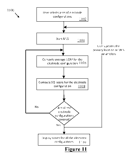
Figure 11 is a flowchart of the MES procedure carried out by the implant;
Fig 12 shows the examples of the MES position configuration methods when stim
electrode is E2; and
Figs 13-16 depict example outputs of the MES.
Description of the Preferred Embodiments
[0035] Figure 1 schematically illustrates an implanted spinal cord
stimulator 100. Stimulator
100 comprises an electronics module 110 implanted at a suitable location in
the patient's lower
abdominal area or posterior superior gluteal region, and an electrode assembly
150 implanted
within the epidural space and connected to the module 110 by a suitable lead.
Numerous aspects
of operation of implanted neural device 100 are reconfigurable by an external
control device 192.
Moreover, implanted neural device 100 serves a data gathering role, with
gathered data being
communicated to external device 192.
CA 03147118 2022-01-12
WO 2021/007615 PCT/AU2020/050725
11
[0036] Figure 2 is a block diagram of the implanted neurostimulator 100.
Module 110
contains a battery 112 and a telemetry module 114. In embodiments of the
present invention,
any suitable type of transcutaneous communication 190, such as infrared (IR),
electromagnetic,
capacitive and inductive transfer, may be used by telemetry module 114 to
transfer power and/or
data between an external device 192 and the electronics module 110.
[0037] Module controller 116 has an associated memory 118 storing patient
settings 120,
control programs 122 and the like. Memory 118 also stores a set of basis
functions comprising
at least one of (a) a compound action potential basis function and (b) an
artefact basis function,
to facilitate fitting or refinement of device operation based on ECAP quality
scores. External
device 192 also stores a set of basis functions comprising at least one of (a)
a compound action
potential basis function and (b) an artefact basis function to permit clinical
fitting based on
ECAP quality scores. Controller 116 controls a pulse generator 124 to generate
stimuli in the
form of current pulses in accordance with the patient settings 120 and control
programs 122.
Electrode selection module 126 switches the generated pulses to the
appropriate electrode(s) of
electrode array 150, for delivery of the current pulse to the tissue
surrounding the selected
electrode(s). Measurement circuitry 128 is configured to capture measurements
of neural
responses sensed at sense electrode(s) of the electrode array as selected by
electrode selection
module 126.
[0038] Figure 3 is a schematic illustrating interaction of the implanted
stimulator 100 with a
nerve 180, in this case the spinal cord however alternative embodiments may be
positioned
adjacent any desired neural tissue including a peripheral nerve, visceral
nerve, parasympathetic
nerve or a brain structure. Electrode selection module 126 selects a
stimulation electrode 2 of
electrode array 150 to deliver a triphasic electrical current pulse to
surrounding tissue including
nerve 180, although other embodiments may additionally or alternatively
deliver a biphasic
tripolar stimulus. Electrode selection module 126 also selects a return
electrode 4 of the array
150 for stimulus current recovery to maintain a zero net charge transfer.
[0039] Delivery of an appropriate stimulus to the nerve 180 evokes a neural
response
comprising a compound action potential which will propagate along the nerve
180 as illustrated,
for therapeutic purposes which in the case of a spinal cord stimulator for
chronic pain might be
to create paraesthesia at a desired location. To this end the stimulus
electrodes are used to deliver
stimuli at 30 Hz. To fit the device, a clinician applies stimuli which produce
a sensation that is
CA 03147118 2022-01-12
WO 2021/007615 PCT/AU2020/050725
12
experienced by the user as a paraesthesia. When the paraesthesia is in a
location and of a size
which is congruent with the area of the user's body affected by pain, the
clinician nominates that
configuration for ongoing use. This clinical fitting process is conventionally
laborious, however
the presently described embodiments provide means for automated assessment of
the device
fitting on the basis of ECAP quality scores, including the stimulation
configuration and
recording configuration, to improve efficiency of this fitting process.
[0040] The device 100 is further configured to sense the existence and
electrical profile of
compound action potentials (CAPs) propagating along nerve 180, whether such
CAPs are
evoked by the stimulus from electrodes 2 and 4, or otherwise evoked. To this
end, any
electrodes of the array 150 may be selected by the electrode selection module
126 to serve as
measurement electrode 6 and measurement reference electrode 8. The stimulator
case may also
be used as a measurement or reference electrode, or a stimulation electrode.
Signals sensed by
the measurement electrodes 6 and 8 are passed to measurement circuitry 128,
which for example
may operate in accordance with the teachings of International Patent
Application Publication No.
W02012155183 by the present applicant, the content of which is incorporated
herein by
reference. The present invention recognises that in circumstances such as
shown in Figure 3
where the recording electrodes are close to the site of stimulation, stimulus
artefact presents a
significant obstacle to obtaining accurate recordings of compound action
potentials, but that
reliable accurate CAP recordings are a key enabler for a range of
neuromodulation techniques.
[0041] In particular, the recording of ECAPs enables the device to enter a
closed loop
feedback mode, whereby a target ECAP level is continually sought by the device
and whereby
the device responds to perturbations in the feedback loop such as postural
changes by adjusting
future stimulation pulses. However feedback operation depends critically on a
quality of the
response recordings being obtained by the device. While quality can be
reliably assessed by
suitably experienced human clinicians, this is laborious. Quality can also be
assessed by
obtaining a full growth curve for each configuration, representing the growth
in ECAP amplitude
in response to increasing stimulus current. This allows a check of whether
that configuration
yields a growth curve with a clear threshold (a stimulus current below which
no ECAPs arise),
and also whether the growth curve is monotonic increasing above the threshold
which is
important for feedback loop stability. However, obtaining and assessing a
growth curve is also
laborious.
CA 03147118 2022-01-12
WO 2021/007615 PCT/AU2020/050725
13
[0042] The present invention thus provides a system and method for automated
assessment of
a quality of neural response recordings.
[0043] In more detail, the present embodiment decomposes each neural
recording by
determining at least one parameter which estimates at least one of a compound
action potential
and an artefact, using the set of basis functions in memory. This is thus a
method for separating
composite signals when signal components belong to a closed space of signals
that may be
represented by distinct basis sets. In neuromodulation this is used to
separate the `ECAP part'
and the 'artefact part' of the recorded signals.
[0044] A composite signal is a signal that is constructed by the sum of
other signals, which
will be referred to here as the underlying signals. The basis element signal
separation approach
of the present invention estimates the underlying signals of the composite
signal given only the
composite signal, and without knowledge of the exact underlying signals. The
present
embodiment provides a blind signal separation algorithm which is able to
assume some
knowledge about the underlying signals. Namely, the present embodiment
recognises that it can
be assumed that each underlying signal may be represented by a set of basis
functions. Unlike
blind signal separation algorithms with multiple inputs and one output, the
present embodiment
produces a deterministic estimate of the underlying signals by leveraging this
assumption.
[0045] In the field of neurostimulation, a mixed signal may be a combination
of an ECAP and
stimulus artefact. In some instances, there will be a need to decompose the
signals and analyse
the components. Analysing the individual components may reveal characteristics
of the signal
components which may be used in numerous advantageous ways. In some cases,
analysing the
components of the mixed signals may reveal errors in the system. Further,
there may be
situations where the mixed or composite signal has a dominant, but
superfluous, component
masking an essential component. In such cases, the mixed signal must be
decomposed into its
components, eliminate the superfluous component, and analyse the essential
component and the
characteristics thereof.
[0046] The present embodiment decomposes a mixed signal by determining at
least one of the
plurality of signals constituting the composite signal from a set of basis
functions. The
embodiment separates composite signals into their underlying components by
modelling each
underlying component with a basis. This embodiment may be applied in
neuromodulation in the
separation of ECAP waveforms form artefact waveforms (as well as noise) given
a signal
CA 03147118 2022-01-12
WO 2021/007615 PCT/AU2020/050725
14
recording which is a mixture of these signals. This yields more robust feature
extraction from the
ECAP, including the ECAP magnitude which is a feature used by the closed loop
control system
of Figs 1-3. Additional features such as ECAP peak positions may also be
measured more
robustly, which is of scientific benefit. The present embodiment estimates
both artefact and
ECAP simultaneously, where ECAP and artefact signal contributions are balanced
to 'best'
represent the recorded signal. The present embodiment produces a noiseless
ECAP estimate and
subject to the definition of the ECAP basis set, can impose certain signal
properties (e.g. a
baseline of OV). Further, the present embodiment is efficient (0(n)) and runs
in a deterministic
time (unlike non-deterministic methods), which means that it may be
potentially integrated into
firmware, giving improved, real-time ECAP magnitude estimates without the need
of a human
tuned filter.
[0047] Fig.4 illustrates a scrubber process 400. A scrubber is an algorithm
that estimates the
ECAP and Artefact components of some composite signal, as depicted at 410. A
composite signal
is defined as a signal composed of the sum of multiple distinct elements. In
the context of ECAP
measurement the components of a composite measurement are the artefact, the
neurophysiological
response to the stimulus (the ECAP), and everything else. The primary goal of
scrubber 420 is to
isolate the ECAP. However, artefact estimation is usually a by-product of this
task and is useful in
and of itself as insights into the mechanism of artefact will help us to
minimise it in future designs.
What is left over consists of electronic noise and neurophysiological noise
independent of
stimulation.
[0048] The present embodiment adopts the following process. Each underlying
signal is
represented as a linear combination of basis functions. Consider a composite
signal with two
underlying signals:
o-(x) = f (x) + g (x) ak (i)k (x) +113i (x)
[0049] Basis functions are derived empirically based on experience and
alternate models of
underlying signals. For the purposes of explanation, consider them to be
constant. Computing the
pairwise inner produces of basis functions and the inner product between each
basis function and
the composite signal, one may write down a set of linear equations that may be
solved with matrix
inversion to obtain the sets of coefficients alpha and beta. Given the alpha
coefficients, one may
then write down the basis representation ofAx), thus estimatingf(x).
Similarly, one may estimate
g(x) given the beta coefficients. This method is not limited to composite
signals containing two
CA 03147118 2022-01-12
WO 2021/007615 PCT/AU2020/050725
components, but the problem it is applied to in the described neuromodulation
field has just two
components.
[0050] The basis element signal separation approach of the present
embodiment is a
mathematical tool for deconstructing composite signals. Consider a signal
containing an ECAP
componentf(t) and an Artefact component g(t). The signal that we measure in a
patient a(t) may
therefore be expressed as:
a(t) = f (t) + g (t) + e(t)
where e(t) is some noise. Closed loop stimulation works because the ECAP
component of a given
signal has a regular shape which resembles two periods of a dampened
oscillation. In a similar
vein, closed loop stimulation would not work if the artefact component of the
signal did not have
a regular shape. In order to measure ECAP amplitude we filter out most of the
artefact using the
detector, which assumes that the artefact has a regular exponential-like
shape.
[0051] The present embodiment operates on the assumption that ECAP and
artefact signal
components belong to distinct families of functions. That is, ECAPs are always
short oscillatory
events, whilst artefacts are exponential-looking signals. For each distinct
family of functions we
can predefine a basis to represent it. For suitable basis functions, the basis
coefficients can be
calculated and the ECAP and artefact basis expansions can each be isolated.
The ECAP basis
expansion then provides us an estimate of the ECAP component, free from
artefact.
[0052] The calculation of basis coefficients balances the contributions of
each of the basis
functions in such a way that the overall signal is approximated as best as
possible. In other words,
the estimated ECAP and Artefact contributions are balanced so as to best model
the signal that has
been recorded. In order to do achieve better performance, the present
embodiment assumes that
all ECAPs belong to a certain family of functions and that ECAP shapes outside
of this family do
not exist. At the time of writing, ECAPs with late responses such as those set
forth in
W02015070281 are outside the family of ECAP functions used by the present
embodiment and
therefore cannot be estimated properly. Therefore, other Scrubbers may be more
appropriate to
use when working with signals not adequately modelled by the ECAP basis in use
at the time.
[0053] The method described above forms the block in the signal flow
diagram of Fig. 5. Pre
and post processing are used, in some embodiments, to improve signal
estimates. For example,
pre-processing can be used to reduce high frequency noise in the signal. The
feedback mechanism
however is used to improve the construction of basis sets. A crude 'first
guess' basis may be used
CA 03147118 2022-01-12
WO 2021/007615 PCT/AU2020/050725
16
to approximate the signal and the estimates that are produced can be used to
refine the basis set on
subsequent passes. For example, the first pass might guess an ECAP basis in
order to get a good
estimate of the artefact. Subtracting the artefact from the signal and using
signal correlation
methods can be used to refine the choice of ECAP basis. Re-running the
algorithm with the
improved basis will yield better estimates of both the ECAP and the artefact.
[0054] Artefact is modelled by the present embodiment using three basis
functions:
. õ ( 16.384 x 10³ Nk
c,53(t) =-- exp
7,0
[0055] The unit basis function 0/ captures the DC content of the measured
signal. The linear
basis function 02 captures the component of Artefact due to amplifier drift.
The exponential basis
function 03 captures the chemical charge relaxation component of the Artefact.
The decay constant
of the exponential component can be any suitable variable and the value above
was determined
empirically based on model performance against a library of human Artefact
recordings. Different
devices may present different artefact and/or ECAP outcomes and may
consequently require
different constants, which can be similarly empirically obtained.
[0056] Once the algorithm of the present embodiment is applied, the
Artefact component of the
signal is represented by:
A(t) ------------------------- (t) + 1309(t) y0(t)
[0057] This model, while simple, has been applied to many thousands of
representative human
patient neural recordings and has been found to perform well. In combination
with the ECAP basis
functions, the combined model accurately estimates the recorded signal.
[0058] Unusual neurological Artefact such as background neuronal activity
or late response are
not modelled in the present embodiment, but may be incorporated in accordance
with alternative
embodiments of the invention. Estimates obtained from the approach of the
present embodiment
will remove such features and therefore the outcome cannot be relied upon in
the measurement of
non-ECAP neurological features, at least in this embodiment.
[0059] An ECAP basis function is defined using the product of a Gamma
probability density
function, with parameters k = 1.7 and 0 = 0.60,
CA 03147118 2022-01-12
WO 2021/007615 PCT/AU2020/050725
17
c(t
(I ftlk-1
[0060] This is a piecewise function composed of one period of a sine wave
followed by an
exponential function such that the derivative is continuous at their boundary:
C < Iff
"
CI) = sirt(27,ft) ¨ atrairt(0/W < t
e2:VO-1/f) : ::: "csil fin(C)/2R1
where C = 0.37. The two components and their product are represented in Figure
6. There is only
one morphology parameter in this FPAP model; the frequency of the sinusoidal
component: f. As
can be seen above, the timescale of the Gamma PDF is scaled accordingly. This
model was arrived
at through the hand fitting of elementary functions to simulated ECAP models.
[0061] By scaling the time axis by v and applying an offset to: v (t - to),
we can stretch and shift
an ECAP basis function in time. Let such a stretched and scaled ECAP be called
a parametric
ECAP basis function: cov,to(t).
[0062] There are two distinct ECAP models. One for singled ended measurements
and another
for differential measurements. The single ended ECAP basis consists of one
parametric ECAP
basis function and the ECAP E is represented by:
E (t) = r h. s- i-,u t(,) , , (t )
- õ/ , \,
[0063] The differential ECAP basis is formed by the difference of two
parametric ECAP basis
functions giving the following ECAP model
E(t) ¨
¨
[0064] In either model, the time stretch (corresponding to the ECAP
oscillation frequency) and
the time offset are chosen such that lc or K+ is positive and ic- is negative.
A sweep of ECAP
frequencies and offsets are tested by the present embodiment to ensure this
condition holds. The
frequency and offset selected to model the ECAP component of a recorded signal
are chosen such
that the fit to the recording using both ECAP and Artefact models is as good
as possible.
CA 03147118 2022-01-12
WO 2021/007615 PCT/AU2020/050725
18
[0065] It should be noted that the single ended ECAP model assumes fixed
ratios between peak
heights and peak times. Neurophysiological parameters such as width at half
height or the ni : p2
ratio are entirely determined by the temporal stretch v applied to the
parametric basis function.
[0066] As with Artefact, this assumption has been validated by fitting
parametric basis
functions to real-world single ended measurements.
[0067] In the case of the differential model, such neurophysiological
parameters are able to
vary independently of v+ and v- and additionally depend on the composition of
the ECAP estimate.
That is, K+ and provide additional degrees of freedom. Although relative
neurophysiological
parameters are able to vary they have restricted freedom compared to more free-
form ECAP
models. As with the single ended ECAP assumption, this model constraint has
been validated by
fitting the differential ECAP basis to real-world differential measurements.
[0068] The range of parametric ECAP frequencies is limited to a linearly
spaced set of
frequencies between 500Hz and 2kHz. The upper limit of 2kHz was chosen to
minimise the
interference of broad spectrum (up to 8kHz) noise on the parameter selection
procedure. The lower
limit of 500Hz was chosen to limit the interference of the Artefact on the
parameter selection
procedure. A slow enough parametric ECAP will closely resemble Artefact in a
confined window
of time. The range of offsets that are tested was chosen to be significantly
wide to model real-
world ECAPs, but reasonably constrained to maintain computational performance.
[0069] Up until this point, we have assumed that each recorded signal contains
an ECAP.
However, in practice this is never the case for signals that are sub-
threshold, that is, where the
applied stimulus was insufficient to recruit any neural response, so that the
recorded signal
necessarily does not include any ECAP in such circumstances. Including ECAP
basis functions in
the model for a sub-threshold signal poses a problem, as an ECAP would be
fitted to the noise in
the signal and the estimate would be meaningless. Additionally, the Artefact
component of the
signal would be misrepresented as ECAP and Artefact features are balanced in a
combined model.
[0070] It is therefore desirable to include a mechanism that detects the
presence of ECAP in a
signal so that the ECAP basis may only be included in the overall model when
an underlying
ECAP is authentic. The present embodiment incorporates such a mechanism. The
signal is
modelled using an Artefact only basis and a combined ECAP and Artefact basis.
A set of signal
features is derived from the estimates produced by both models and combined
with signal features
CA 03147118 2022-01-12
WO 2021/007615 PCT/AU2020/050725
19
from the recorded signal. A series of signals known to contain both ECAP and
Artefact or just
Artefact were analysed by the present embodiment and the derived set of
features saved. Machine
learning is used to train a classifier with categories: `ECAP' or 'no ECAP'.
After sufficient training
the resulting classifier is able to automatically judge the presence of ECAP
in a signal. The present
embodiment is rated to detect ECAP in signals containing ECAP with an accuracy
of 85% and to
reject ECAP in signals containing only Artefact with an accuracy of 95%.
[0071] Combining these concepts together, we arrive at the complete
algorithm of the present
embodiment as depicted in Fig. 7.
[0072] The recorded signal is first modelled using an Artefact only basis,
under the assumption
that it contains no ECAP. Regardless of ECAP presence this will provide an
estimate of the
Artefact via the basis coefficients. If an ECAP is present this estimate may
be refined by including
an ECAP basis as well. The initial Artefact estimate is subtracted off the
recorded signal to help
better determine the parametric ECAP basis. The estimated Artefact and derived
features are
passed to the `ECAP Presence Classification' (or ECAP detector) block for
later use.
[0073] Once the parameters for the Parametric ECAP Basis are determined,
the coefficients of
the ECAP and Artefact basis in conjunction are then determined. Resulting
estimates and feature
sets passed to the ECAP detector.
[0074] The ECAP detector now has everything it needs in order to classify
the presence of
ECAP in the recorded signal. Based upon its decision, either the ECAP and
Artefact estimates are
returned or the Artefact only estimate is returned.
[0075] The method steps are as below:
a.Capturing/ recording a composite signal, wherein the composite signal has
two or
more additive components
b. Selecting a first basis set, corresponding to the first signal
component, from a pool
of basis sets. Selecting a second basis set, corresponding to the second
signal
component, from a distinct pool of basis sets.
c.Determining a first component and the second component of the composite
function
based on the bases functions. Determining an estimate for the first component
as a
linear expansion of the first basis set, and an estimate for the second
component as
a linear expansion of the second basis set.
CA 03147118 2022-01-12
WO 2021/007615 PCT/AU2020/050725
d. Iteratively improving the basis sets using the estimated components from
the
previous iteration.
[0076] The following explanations delve into the mathematics behind the
present embodiment.
Coefficient Determination is as follows. Let a(t) be the signal we record, and
J(t) and g(t) the
underlying ECAP and Artefact components respectively. The problem we are
attempting to solve
is to find estimates forAt) and g(t), which we do not know, using the recorded
signal a(t), which
we do know. For simplicity, we assume there is no noise in the signal.
Therefore,
a(t) = f (t) + g(t)
[0077] Now suppose that J(t) may be represented using a finite set of basis
functions
{40k (t): k E {1, 2, ... n}}. Similarly, suppose that At) may be represented
using a finite set of basis
functions {01(t): j E {1, 2, ...m}} all distinct from the set used to
representAt). ThenAt) and g(t)
may be expanded over their respective bases,
:(2) IV)
(3) g(t) = bimo
[0078] Then by simple substitution:
.m.
a (t) = ok.0,#) ------ bio,(t)
=
[0079] At this stage of the problem, the basis sets are known but the
coefficients for the specific
signal a(t) are not. With the coefficients we may recover estimates forAt) and
g(t). We will recover
them now.
[0080] Consider the following functional inner product for any basis
function off pi(t) and by
the linearity of inner products we have:
(4) (:(7(.t)t i(t)) ELI ok(41k(.0t. 4'):/(t)) E311.11)..i(Oi(t)
4µ)i(t1))
[0081] Similarly, consider the functional inner product for any basis
function of g: 01(t)
(5)
(9-0), AO)) --= .1 a*. (A::(1) (0) + E (fkin.431.0)).
CA 03147118 2022-01-12
WO 2021/007615 PCT/AU2020/050725
21
[0082] Equations (4) and (5) provide us with a system of n + m linear
equations with n + m
unknowns (the coefficients ak and 1)1). Thus, determining the coefficients is
a matter of solving a
linear equation:
Hv=b
where
( G'IOP1) (4"li 'M
11 =
- . .
.... , .. .
6 -
_
:
w5m,(PyrA) \
[0083] Thus the coefficients may be solved via H-lb. The matrix H is
invertible if and only if
none of the basis functions from the ECAP basis belong to the span of the
Artefact basis and vice
versa, and basis functions with ECAP and Artefact bases are distinct. Basis
functions should be
scaled to unit power so that comparatively large or small inner products do
not introduce
computational error during the inversion of H.
[0084] In practice there is noise in the signal which is not modelled by
either basis. However,
introduced errors will be minor since the inner product of an independent
noise source and any
signal is zero for an inner product taken over an infinite time interval.
Limiting the inner product
to a finite number of samples when calculating b will propagate some error,
however, this error is
not significant.
[0085] ECAP Parameter Determination is as follows. The parametric ECAP basis
is
determined using the recorded signal with the initial Artefact removed and any
residual baseline
subtracted. Let this signal be called the 'refined recording'. A correlation
mesh is determined by
sweeping a range of basis ECAP frequencies and offsets and taking the dot
product between the
refined recording and each parametric basis function.
[0086] For single ended and differential mode, the present embodiment
samples 16 linearly
spaced frequencies between 800Hz and 2kHz and offsets from -7 samples to -1
samples inclusive.
This range of frequencies and offsets was found to work well against test
signals observed in
human subjects but these ranges may be extended. Extending them too far will
allow the
parametric ECAP to lock onto noise or the Artefact so do so with caution. The
highest positive
stationary point of the correlation mesh determines the parameters of the
first ECAP basis element.
If the measurement is single ended, then this is the only ECAP basis element.
CA 03147118 2022-01-12
WO 2021/007615 PCT/AU2020/050725
22
[0087] In the case of a differential ECAP measurement, a new correlation
mesh is calculated,
sampling 16 linearly spaced frequencies between 500Hz and the frequency of the
previously
determined basis element. It is assumed that the reference is always further
away from the stimulus
than the recording electrode. This allows us to exploit human neurophysiology
since ECAP
frequency monotonically decreases with recording distance. In a similar vein,
offsets are tested
between the previous ECAP basis offset and 12 samples. Again these ranges were
empirically
chosen to work well with good signals from humans. Instead of using the
highest positive
stationary point of the correlation mesh, the most negative stationary point
instead determines the
parameters of the secondary basis function. If there are no negative
stationary points, only the
primary basis function is utilised.
[0088] The majority of blind signal separation algorithms assume that the
underlying signals
are statistically independent and use statistical signal processing techniques
to estimate the
underlying signals. The problem of ECAP and artefact estimation cannot be
solved in this way
because the underlying signals are fundamentally dependent on one another.
Instead the present
embodiment assumes that each underlying signal may be expressed as a linear
combination of
basis functions (a stronger assumption) limiting its application to processes
where there is already
some knowledge of the underlying signals before they are recorded in the form
of a composite
signal.
[0089] The Artefact Model lists the basis functions used to model the
Artefact present in our
hardware/recordings. The FPAP model is a singular basis function used in the
total ECAP basis
set. In practice we use one FPAP for single ended measurements and two FPAPs
for differential
measurements to take care of the reference electrode effect arising with
differential measurements
taken between two recording electrodes.
[0090] Alternative embodiments are further provided. In this embodiment the
process of Fig.
4 is instead implemented as follows.
[0091] An Artefact Estimation Scrubber is a Scrubber that attempts to
estimate only the
Artefact component of the signal g(t) and derives an ECAP estimate using a(t) -
g(t).
Exponential Scrubbers model the Artefact as the sum of exponential functions.
There are three
such models envisaged here:
CA 03147118 2022-01-12
WO 2021/007615 PCT/AU2020/050725
23
Exponential Time domain representation
Single = 4exp(¨.bt) + 4
Double g(t) = a exp(-60 + cexp(¨.4) + h
Tilt).le g(t) etexp( ¨14) 4- r exp(¨eft.) f
Table 1: The Exponential Scrubber Artefact models
[0092] A non-linear optimisation is performed using the simplex hill-
climbing Nelder Mead
algorithm where the parameters a; b; c; d; e; f; g and h are all tuned to
minimise the value of a
cost function. The non-linear optimisation minimises the sum of the squares
error between the
estimated Artefact samples and the samples of the recorded signal.
Mathematically, the cost
function is defined as:
= = 2
-E(91 a) .........................
[0093] Non-linear optimisations are non-deterministic algorithms, meaning
that they do not
terminate in a predictable or pre-determinable amount of time. That means that
it is possible to
provide such a scrubber with a signal that cannot be scrubbed in a reasonable
time frame.
Further, non-linear optimisations can become stuck in local minima, failing to
find the true
optimal solution. In practice, this Scrubber works well but it has limitations
that should be
known before putting it to general use. Nevertheless such embodiments do have
uses in certain
applications.
[0094] A further embodiment is a fractional pole Scrubber works on the same
principles as
the exponential Scrubbers where a non-linear optimisation is used to determine
parameters a; k;
a and h of the following Artefact model:
Xt.) = 01.exp(¨)1) = -t- n
[0095] Yet another embodiment is a Complex Pole Scrubber. If we assume that
the artefact is
a second order response (a double exponential is a subset of this kind of
response), then we can
estimate the parameters of the second order response that fits the raw signal.
For discrete signals,
the artefact g follows the model:
CA 03147118 2022-01-12
WO 2021/007615 PCT/AU2020/050725
24
¨ .1- =
g[n] ¨ b . q['t ¨ 1.] c ,, g n: ¨ 2]
1,
[0096] Given a sequence of samples we may write down the matrix equation:
,,,
- = .
1.= A (
f
where,
' oltz.1 '. g[n - f g[1.1
(
,
A , g[n - 2: g[n - 31
f''''' -
. .
. .
[0097] The coefficients b and c may therefore be determined by computing:
(b)...... G4T 4)-1 IT ii
C
[0098] The preceding analysis then feeds into an algorithm called a Signal
Quality Indicator
(SQI) that assigns a quality score to a set of ECAPs recorded under the same
stimulator program.
Such algorithm may be used in signal quality indicators in clinical data
analysis software and
clinical user interface software.
[0099] In order to build a system for automated assessment of the quality
of a signal, the
properties of a signal that make it 'good' as opposed to 'bad' must be
defined. Test cases on the
spectrum of 'good' to 'bad' may then be used to assess the performance of an
SQI. However, no
such definitions of signal quality exist because it is unclear what properties
of individual signals
lead to poor clinical results in closed loop spinal cord stimulation. In
contrast it is relatively easy
to assess the quality of a growth curve, which is a known indicator of
clinical success for a
closed loop patient.
[00100] Therefore, the quality of a group of signals recorded under the same
stimulator
configuration is defined as the prediction of the quality of the growth curve
that would be
measured using the same stimulator configuration. However, growth curves are
time consuming
to collect. Objective guidance prior to growth curve collection on which
programs will yield
satisfactory growth curves is therefore sought after by field clinical
engineers.
CA 03147118 2022-01-12
WO 2021/007615 PCT/AU2020/050725
[00101] A stimulator program is defined as the combination of the stimulation
waveform
parameters, stimulation frequency and electrode arrangement. Signals are
measured with the
same stimulator program when these quantities are kept constant. The
stimulation current may
vary across signals because the present embodiment operates under the
assumption that ECAP
morphology does not change with stimulation current, and that only the peak to
peak magnitude
of the ECAP varies with current.
[00102] The Signal Quality Indicator (SQI) of the present embodiment assesses
the quality of
multiple signals recorded with the same stimulator program in open loop mode
(i.e. feedback not
enabled), and outputs a measure of predicted growth curve quality as a single
number between 0
and 1. A higher score indicates that signals recorded with said program are of
a higher quality
and are more suitable for use in growth curve measurement. Multiple recordings
(or signals) are
required to perform an assessment because quality estimates should be robust
to individual
signals of unusual quality. Instead it is desirable for the SQI to provide an
indication of the
general signal quality of a stimulator program.
[00103] Figure 8 depicts the architecture of an SQI system in accordance with
one
embodiment of the invention.
[00104] It is to be noted that alternative embodiments may derive an ECAP
signal quality score
by reference to reference ECAPs which are derived by other means. For example,
a residual
signal may be obtained by subtraction of an artefact estimate from a recorded
signal, and may
simply be compared to a clinically verified template ECAP saved in the device
since a time of
fitting. The clinically verified template ECAP may for example comprise an
ECAP recording
obtained significantly above threshold to improve SNR, and verified by a
clinician as being
suitable to be stored in the device to serve as such a template.
[00105] Growth curves of varying quality were scored for their usability in
closed loop SCS
therapy by experienced clinicians. Subsets of signals recorded with same
program used to
produce these growth curves were used as a Signal Quality Test Library.
Performance of an SQI
is assessed by its ability to produce quality scores that give consistent
rankings with those
assigned to the programs in the Signal Quality Test Library. Algorithm
tuning/learning was not
performed on the Signal Quality Test Library, but rather on a Signal Quality
Training Library.
CA 03147118 2022-01-12
WO 2021/007615 PCT/AU2020/050725
26
[00106] The SQI receives each input signal as a list of samples. The SQI also
receives the
stimulation current alongside each input signal. The SQI produces a quality
estimate upon
receiving 4 or more signals as input, using multiple signals. The SQI is used
to assess the quality
of a program so that high quality programs may be more easily selected for
clinical use.
[00107] Additionally, quality might be assessed by measuring the consistency
of the estimated
ECAP component of a signal. Inconsistent estimates indicate that either signal
quality is poor
and consequently ECAP estimation is poor or that the modelling of the signal
components is
poor, as may occur when presented with degenerate signals. The SQI outputs a
quality estimate
in the form of a decimal number between 0 and 1.
[00108] The intention of a quality indicator is to enable FCEs to find good
programs for
patients faster without having to rely upon experience and developed intuition
about signal
quality. Presenting multiple outputs may reduce the mental/experiential burden
placed on FCEs
but will still require training or developed intuition in aggregating the
meaning of multiple
indicators. Providing a single indicator, as is provided by the present
embodiment of the
invention, is therefore desired.
[00109] The approach of the present embodiment can be represented in pseudo
code by:
score = (scoreParams.DetectionRate * scoreParams.MeanPositiveCorrelation)
/ ((scoreParams.StdPosFreq + 100*scoreParams.StdPosOff)
30/(scoreParams.DetectionRate + le-3));
return 1.0- 1.0 / (1.0 + alpha * score); // converts a score from [0, inf]
into a score
from [0,1]
[00110] The signal quality indicator (SQI) is a tool used to guide FCEs in the
selection of
programming parameters. The SQI is a number between 0 and 1 which, in
conjunction with SQIs
measured across different patient programs, provides insight into which of
those programs will
perform the best. For example, if Program A has an SQI of 0.9 and Program B
has an SQI of 0.5,
the clinical engineer would opt for Program A. In this sense the SQI can be
considered to be a
predictor of patient outcome.
[00111] Signal quality may be interpreted in one of two ways: objective and
subjective.
Objective signal quality is represented by objective signal properties such as
signal to noise,
which no amount of signal processing can remove. Subjective signal quality is
a measure of how
CA 03147118 2022-01-12
WO 2021/007615 PCT/AU2020/050725
27
much information can be extracted from a signal given the capability of the
implant in use. This
subjective signal quality category covers signal features such as signal to
artefact ratio. Ideal
artefact removal approaches not limited by processing time and capacity can
improve subjective
signal quality, but given the limited filter capability available in a
practical implant and in
practical clinical programming sessions, the present embodiment instead makes
a prediction of
patient outcome within the constraints of such applications. The signal
quality indicator used in
various embodiments of the invention can involve a combination of objective
and subjective
signal qualities. Under the assumption that the neurophysiological response
varies only in
amplitude across time but not in morphology, a subjective SQI will take into
account the
variability of certain signal features, thus requiring a time sequence of
signals. An objective SQI
however, may produce a score based on individual signals.
[00112] The SQI of the described embodiment is derived from a time sequence of
signal features.
The features utilised are:
= ECAP detection, as determined by the basis element signal separation
mechanism
described in the preceding;
= Model parameters, also as estimated by the mechanism described in the
preceding fitting
methods;
= model correlation, also as computed by the mechanism described in the
preceding; and
= stimulus current.
[00113] Given the time sequence of features, the derived SQI time sequence is
determined.
The present embodiment provides for signal quality indicators that vary over
different time
scales. Estimates of the variability of certain signal features require some
sample size before an
estimate may be produced. Using a small sample size will provide a fast
updating SQI compared
to a large sample size. The fast updating SQI used by the present embodiment
is defined as
follows:
Jr+.
8
(IV f .1rd
< s,
where [0, 1] is the rate of detection, x--4- (E [0, 1] is the average
correlation measured
between the scrubbed signal and the selected reference electrode ECAP model,
f+ and d+ are,
respectively, the frequency and delay parameters estimated for the reference
electrode ECAP
model, and a and 0 are empirical constants used to appropriately weigh the
contributions of the
variance estimates.
CA 03147118 2022-01-12
WO 2021/007615 PCT/AU2020/050725
28
[00114] Signal statistics are computed over 32 samples, requiring at least 32
signals before the
first SQI score s may be computed. After this step the score s is not confined
to the specified
range of [0; 1] but instead can extend out to co if both parameter variances
are 0. Accordingly, in
a next step a normalisation is applied to s, to produce a Normalised Score, as
follows:
1
f
S =
ye.x.p 7 8
[00115] Now s' E [0, 1]. The constants 1 and T have been tuned using clinical
experience to
give the greatest differentiation between quality scores in a clinical
setting. If these parameters
are incorrectly chosen, scores will inappropriately tend to reside close to 1
or close to 0 for a
majority of the time.
[00116] A slow updating SQI is also utilised. The benefit of a slowly changing
SQI is that
scores are assigned over a long history of signals and are not overly
sensitive to local signal
changes. As such, the clinical engineer will have scores that are stable and
will be better
equipped to choose a program as compared to SQIs that constantly change the
'best' choice of
program based on local signal properties. A slow varying SQI may be obtained
by increasing the
sample size above. However, in this embodiment, a weighted ensemble average is
adopted.
Every n(= 32) samples, s' is computed. A slow varying SQI is then derived from
the weighted
average:
v.. t,
I Ld 0 k = 1 7 k
Al =
tiz(nk)
i
[00117] where n (2) s the average current at timepoint j taken over the past n
samples, s"
represents the historical evolution of s' but weighted by current. The
motivation for weighting
quality by current is that objective signal quality is expected to improve as
current is increased as
the size of the neurophysiological response with respect to the noise floor is
expected to increase.
Alternative embodiments could use any other program parameter to define a
weighted average in
such a way based on the knowledge that said program parameter is known to
improve the objective
or subjective signal qualities.
[00118] In one embodiment the system is configured so that in the clinical
setting, signal
quality is presented for four different patient program alternatives and each
quality score is
CA 03147118 2022-01-12
WO 2021/007615 PCT/AU2020/050725
29
configured to evolve as new signals are observed. The number display for each
quality score is
scaled to a percentage between 0 and 100 and the clinical engineer may use the
SQI prediction to
narrow in on a patient program prior to enacting a closed loop control
programming procedure
and assessing clinical efficacy.
[00119] Alternative embodiments of the invention could similarly implement an
SQI derived
from any time sequence of signal features including Signal to Artefact Ratio
(SAR), Signal to
Noise Ratio (SNR) or frequency domain features such as spectral peak
positions. The time
sequence of other device program parameters may also be included in the signal
quality estimate
in some embodiments.
[00120] Embodiments of the present invention may thus be of particular
assistance in
automating programming of the device for each individual patient as much as
possible.
[00121] Embodiments of the invention may provide particular benefits in
relation to
neuromodulation utilising closed loop feedback on the basis of observed
outcomes, such as
ECAP amplitude. In such feedback systems, a possible behaviour of the loop is
that if the ECAP
signal is lost or the signal to noise ratio becomes too low in some way (e.g.
due to significant
lead migration or an additional noise source) and the measured ECAP amplitude
is reduced due
to such effects (but not necessarily due to an actual reduction in
recruitment), then the system
will increase the stimulus current in order to bring the measured ECAP
amplitude back up to a
specific target. This can result in excess recruitment. Moreover, in the event
of total loss of
ECAP measures, the feedback loop will operate to increase the stimulus current
until it either
hits the Maximum Current Limit, or the compliance voltage limit. Either of
these endpoints can
result in some discomfort to the patient, and more dorsal column activation
than intended. In the
opposite case, if the ECAP amplitude measured is higher than actual
recruitment for some
reason, the current will be driven to 0 mA and the patient will not get any
therapy and/or may
feel intermittent stimulation, which is often frustrating and uncomfortable.
By integrating ECAP
signal quality determination in accordance with the present invention into
such a feedback loop,
the feedback loop operation can be improved by modifying the loop in a manner
to restrain or
preventing such undesirable loop excursions from occurring if the ECAP signal
quality is low.
For example, a simple step would be to halt feedback loop operation entirely
at times when the
ECAP signal quality is below a threshold, and to resume feedback loop
operation at times when
CA 03147118 2022-01-12
WO 2021/007615 PCT/AU2020/050725
the ECAP signal quality is above that threshold or another threshold. The
patient may be
notified of such occurrences.
[00122] Figure 9 illustrates a clinical system in accordance with one
embodiment of the
invention, in which the programming application associated with a clinician
user arranges for the
neurostimulator to carry out an automated scan of all possible configurations
of the recording
electrodes, to thereby obtain a matrix or set of ECAP quality scores for all
possible electrode
configurations.
[00123] The automated scan is also referred to herein as a measurement
electrode scan (IVIES).
Notably, the MES is executed by the implanted device in this embodiment, which
allows for
more rapid execution of the automated MES, thereby hastening clinical fitting
and also
minimising the chance that patient postural changes may affect the comparative
results.
[00124] The results of the MES are presented visually by the programming
application so as to
allow the clinician user to see in real time a signal quality indication (SQI)
for multiple electrode
locations. In particular, the programming application is configured to also
visually present the
estimated neural response to the stimulation as measured in a currently
selected stimulation and
recording configuration, but also simultaneously presents a SQI for multiple
alternatives which
the clinician may wish to consider.
[00125] The measurement electrode scan allows ECAPs from multiple electrode
configurations to be displayed at the same time. It is intended to assist in
optimizing the choice
of measurement electrodes and settings. By default, the measurement electrode
scan will be
automatically started when stimulation is started. The measurement electrode
scan consists of up
to four measurement electrode configurations. the configuration selected by
the user and three
other configurations. The electrodes used in the scan are based on the
location of the stimulation,
measurement and the reference electrodes that are selected in the electrode
display window, refer
to Fig 12.
[00126] The settings to choose electrodes and perform IVIES are as below:
CA 03147118 2022-01-12
WO 2021/007615 PCT/AU2020/050725
31
Button Action
C.?ear SQI clear the SQ1 V3i.ues and :restart the S.Qi
caicirtaons. The
dispiavect umthi EcA.Ps are received.
Stop. / Stort Sc art Stop or Start the measurement electrode 'if:an VAe
StiflIkAatieri
is running. This does not change the automatic start of the scan
klihen stimulation is started.
Position. .Configuration C:hoose the method used to tect up to 3 etectrode
configurations to he used in the .an These configurations are in
addition to the user selected configuration (for exe.mples see
Figure 75)
Button Measurement
Reference
Optioire
(#electrocies from stimulation) 3 6
4 7+
4 ease ;Li.'5}
Fixod MeasurernentA As sefected I cioser
t#etectrodas from setected 1 further
2 further
Fixed Reil-Trent:e, 1 Llur:e4 As .seiected
(4electrocies from aeect.ed further
2 f:urthei-
Fixed Distar3oe I doser4 Icioser
(.4eiectrocies from se ect.ect further I further
further 2 further
DisaMe Enable 5t.W3 Disabie or Enable the measurement eiectrede scan for the
duration of the programming session. When disabled, the
measurement electrode scan will not- be automatically started
when stimulation is started. This control is also available in the
CLS menu tsee Section
[00127] Figure 10 is a state machine diagram representing an implementation of
the IVIES in
accordance with one embodiment of the invention. The primary location is
defined as the
location used by the neurostimulator to calculate the neural response to
stimulation. Necap is
defined as the number of measurement to be used for the averaging of the ECAP.
In the case of
averaging being disabled, Necap is equal to 1. Nmeasurement is defined as the
number of
averaged ECAP required at the defined location. N+ is defined as the ECAP
measurement
electrode location. N- is defined as the ECAP reference electrode location.
[00128] Figure 11 is a flowchart of the MES procedure 1100 carried out by the
implant. In the
first step 1102, the electrode configurations are assigned to the MES program.
This can be
predetermined, or user determined. At 1104 the implant firmware then captures
ECAP
measurements of all the electrode configurations associated with the user
selected setting. In an
exemplary implementation, the considerations while choosing the electrodes may
be that the
selected stimulation, measurement, and reference electrodes must be on the
same lead. Or, that
only 1 stimulation electrode is selected. In this embodiment the measurement
electrode must not
be adjacent to the stimulation electrode, and the reference electrode must not
be on the case of
the implantable pulse generator, although this may be allowed in other
embodiments. The
measurement electrode must be between the stimulation and reference
electrodes. In some cases,
CA 03147118 2022-01-12
WO 2021/007615 PCT/AU2020/050725
32
the primary location set by the user may not be the best location for
capturing good quality
ECAP recordings. The MES program will then suggest the best electrode
configuration for
getting a robust ECAP.
[00129] Fig 12 shows the examples of the IVIES position configuration methods
when the stim
electrode is E2. The MES program is configured to measure ECAPs at each of the
selected
electrode locations until a set number of ECAPs are accumulated. Thereafter,
an SQI score is
calculated using the SQI algorithm at each electrode location. The SQI scores
are computed for
different electrode locations by the programming software, based on strategies
such as fixed
distance, and fixed reference, as shown in Fig 12. The IVIES program stops
upon user
intervention or after computing the score for all the selected electrodes. The
user is provided
with the ECAP quality score at multiple electrodes which allows the user to
select the best
possible electrode combination which captures the best quality ECAPs.
[00130] Example outputs are shown in Figs 13-16. Fig 13 depicts the
measurement electrode
scan GUI window showing four fixed-distance recording electrode
configurations' SQI. It can
be determined by simple observation that E3 referenced to E7 is the best
recording electrode in
this example. Figure 14 illustrates the output when the IVIES scan is stopped
for any reason.
[00131] Fig 15 shows the output SQI = 0% which is produced when no ECAP has
been
detected. These results would suggest that E7 is a poor choice of recording
electrode as no
ECAP is observed irrespective of reference electrode selection. Fig. 16
illustrates the MES
output when investigating which reference electrode is optimal when using E4
is the recording
electrode.
[00132] It will be appreciated by persons skilled in the art that numerous
variations and/or
modifications may be made to the invention as shown in the specific
embodiments without
departing from the spirit or scope of the invention as broadly described. The
present
embodiments are, therefore, to be considered in all respects as illustrative
and not limiting or
restrictive.