Note: Descriptions are shown in the official language in which they were submitted.
CA 03147220 2022-01-12
WO 2021/023890 PCT/EP2020/072326
AEROSOL GENERATION DEVICE WITH BATTERY VENTING SYSTEM
Field of the Disclosure
The present disclosure relates to an aerosol generation device. The
disclosure is particularly applicable to a portable aerosol generation device,
which may be self-contained and low temperature. Such devices may heat,
rather than burn, tobacco or other suitable aerosol substrate materials by
conduction, convection, and/or radiation, to generate an aerosol for
inhalation.
Background to the Disclosure
The popularity and use of reduced-risk or modified-risk devices (also
known as vaporisers) has grown rapidly in the past few years as an aid to
assist
habitual smokers wishing to quit smoking traditional tobacco products such as
cigarettes, cigars, cigarillos, and rolling tobacco. Various devices and
systems
are available that heat or warm aerosolisable substances as opposed to burning
tobacco in conventional tobacco products.
A commonly available reduced-risk or modified-risk device is the heated
substrate aerosol generation device or heat-not-burn device. Devices of this
type
generate an aerosol or vapour by heating an aerosol substrate that typically
comprises moist leaf tobacco or other suitable aerosolisable material to a
temperature typically in the range 150 C to 300 C. Heating an aerosol
substrate,
but not combusting or burning it, releases an aerosol that comprises the
components sought by the user but not the toxic and carcinogenic by-products
of
combustion and burning. Furthermore, the aerosol produced by heating the
tobacco
or other aersolisable material does not typically comprise the burnt or bitter
taste
resulting from combustion and burning that can be unpleasant for the user and
so
the substrate does not therefore require the sugars and other additives that
are
typically added to such materials to make the smoke and/or vapour more
palatable
for the user.
It is desirable to provide a device with improved safety and/or reliability.
There is a safety issue with certain aerosol generating devices powered by
certain types of battery that can experience leaks or degassing events where a
fluid
(liquid or gas) is produced from the battery. For example, lithium ion
batteries are
known to experience degassing events. These events can be slow or small events
that fall within normal behaviour of the battery, and do not necessarily
compromise
CA 03147220 2022-01-12
WO 2021/023890 PCT/EP2020/072326
2
the functionality of the aerosol generation device. However, these events can
also
be rapid events that cause high pressures and damage the device or even cause
the device to explode. Moreover, due to the pressure build-up inside a case of
the
battery, some solid material may be ejected. Ejected material may come from
the
external or internal components of the battery such as pieces of the top and
bottom
cap, top and bottom insulator, gasket, steel can, cathode and anode,
separator,
steel can, portion of aluminum or copper foils with their coating, jelly roll
and the
electrodes for example. Ejected material has usually a very high temperature
in the
range of 400 C to 850 C or more and may trigger a fire in the neighborhood or
harm
a user. Battery self-destruction may occur during charging, discharging and
therefore during the utilization of the aerosol generation device by a user.
This is
particularly dangerous if the device is held in a user's hand or is close to
the user's
face. Additionally, the leaked or degassed fluid may be a hazardous chemical
such
as a flammable or toxic organic solvent.
Summary of the Disclosure
According to a first aspect of the disclosure, there is provided an aerosol
generating device comprising: a housing comprising a mouth end and an
opposing end, the opposing end comprising a vent hole; a battery within the
housing, the battery comprising a vent point in an outer surface of the
battery,
the vent point arranged such that fluid is released preferentially from the
vent
point during degassing of the battery; a fluid directing arrangement within
the
housing. The fluid directing arrangement is configured to define a fluid flow
path
from the vent point of the battery to the vent hole of the housing.
Optionally, the vent point is positioned on one end of the battery and the
fluid directing arrangement comprises an annular support positioned between
said end of the battery and the housing vent hole such that a fluid flow path
is
directed through the annular support from the battery vent point towards the
housing vent hole.
Optionally, the vent point is positioned on one end of the battery, and the
device further compries a vibrator element positioned adjacent to said end of
the
battery; wherein the fluid directing arrangement comprises a vibrator element
support which is configured to hold the vibrator element and direct a fluid
flow
path around the vibrator element from the battery vent point to the housing
vent
hole.
Optionally, the fluid directing arrangement further comprises a baffle
positioned between a side surface of the battery and an adjacent inner surface
CA 03147220 2022-01-12
WO 2021/023890 PCT/EP2020/072326
3
of the housing to seal a space between the battery and housing and restrict a
fluid flow towards the mouth end of the housing.
Optionally, the baffle is positioned towards the mouth end along an
elongate side of the aerosol generation device.
Optionally, the baffle conforms to the shape of the battery.
Optionally, the baffle comprises a concave surface directed towards the
vent hole in the housing such that a fluid flow towards the baffle is
redirected in
the opposing direction towards the vent hole.
Optionally, the fluid directing arrangement further comprises a deflector
plane positioned adjacent to the vent point of the battery, the deflector
plane
configured to redirect a fluid towards the baffle.
Optionally, the aerosol generation device further comprises a vibrator
element positioned between a side surface of the battery and an adjacent inner
surface of the housing
Optionally, the baffle is a support for the vibrator element positioned
between the side surface of the battery and the adjacent inner surface of the
housing.
Optionally, the vibrator element is mounted in a rubber gasket.
Optionally, the vibrator element is arranged to transmit vibrations to the
housing.
Optionally, the vibrator element is configured to vibrate when the heater is
initially turned on, when the heater reaches a predetermined temperature, or
after the heater has been on for a predetermined duration.
Optionally, the gasket is arranged to reduce the transfer of vibrations from
the vibrator element to the battery or the heater sub-assembly.
Optionally, the aerosol generating device further comprises an absorbent
pad positioned adjacent to the vent point of the battery.
Optionally, the absorbent pad is annular and positioned adjacent to the
vent point of the battery.
Optionally, the fluid directing arrangement comprises an annular support
and the absorbent pad is positioned within the annular support.
Optionally, the aerosol generating device further comprises a sticker
positioned over the vent hole on an outer surface of the housing, where the
sticker is configured to be displaced to open the vent hole during degassing
of
the battery.
Optionally, the aerosol generating device further comprises a cavity within
the housing adjacent to the battery vent point configured to receive a fluid
expelled from the battery during degassing.
CA 03147220 2022-01-12
WO 2021/023890 PCT/EP2020/072326
4
Optionally, the aerosol generating device further comprises a battery
support frame which holds the battery, the battery support frame positioned
across the internal volume of the housing so as to seal the battery in one
portion
of the internal volume of the housing.
Optionally, the vent hole comprises a supporting element arranged across
the vent hole to prevent opposing edges of the vent hole from closing.
Optionally, the aerosol generating device further comprises a heater sub-
assembly comprising a heater and a heating chamber with an opening at the
mouth
end of the body, wherein the heating chamber is arranged to receive a
consumable
to be heated and the aerosol generating device further comprises control
circuitry
configured to control the heater to heat the heating chamber to a
predetermined
temperature to heat the consumable and generate an aerosol.
Optionally, the aerosol generating device further comprises a first thermal
insulation sleeve configured to encapsulate the battery.
Optionally, the aerosol generating device further comprises a second thermal
insulation sleeve configured to encapsulate the heater sub-assembly.
Optionally, the first thermal sleeve and the second thermal sleeve each have
a thermal conductivity of 0.12 W/mK.
Optionally, the first thermal sleeve and the second thermal sleeve each have
a wall thickness for the sleeve that is smaller than 10 mm, preferably smaller
than 5
mm.
Optionally, the first thermal sleeve and the second thermal sleeve each
comprise either one of a blanket with fiber and a solid porous material made
of
thermal ceramics.
Optionally, the aerosol generating device further comprises an anti-ejection
means configured to retain solid components ejected from the battery when the
battery runs into a thermal runaway state, the anti-ejection means being
arranged
between the battery and the housing and comprising a first material having a
mechanical strength able to retain the components ejected from the battery.
According to a second aspect of the disclosure, there is provided a housing
for an aerosol generating device, the housing comprising a mouth end, an
opposing
end comprising a vent hole; and a fluid directing arrangement within the
housing.
The housing is configured to receive a battery within the housing, the battery
comprising a vent point in an outer surface of the battery, the vent point
arranged
such that fluid is released preferentially from the vent point during
degassing of the
CA 03147220 2022-01-12
WO 2021/023890 PCT/EP2020/072326
battery. The fluid directing arrangement is configured to define a fluid flow
path from
the vent point of the battery to the vent hole of the housing.
Brief description of the Drawings
5 Figures 1A and 1B schematically illustrate an aerosol generation
device;
Figures 2A, 2B and 20 schematically illustrate fluid flow in an aerosol
generation device according to a first embodiment;
Figures 3A and 3B schematically illustrate internal features of an aerosol
generation device according to a second embodiment;
Figures 4A and 4B schematically illustrate features of aerosol generation
devices according to further embodiments;
Figures 5A to 5E schematically illustrate features of aerosol generation
devices according to further embodiments;
Figures 6A and 6B schematically illustrate features of aerosol generation
devices according to further embodiments;
Figure 7 schematically illustrates an opposing end of a housing of an aerosol
generation device according to embodiments;
Figure 8 schematically illustrates a sticker and an opposing end of a housing
of an aerosol generation device according to an embodiment;
Figure 9 schematically illustrates an example embodiment comprising a
thermal insulating sleeve around the battery;
Figure 10 schematically illustrates an example embodiment comprising a
thermal insulating sleeve around the heater sub-assembly;
Figure 11 schematically illustrates an example embodiment comprising an
anti-ejection means configured to retain solid components.
Detailed Description
In order to improve safety and reliability, an aerosol generation device may
be designed on the basis of accepting the possibility of leaks or degassing
from a
battery, and designing the aerosol generation device to reduce the risks to
the user
associated with such events.
A battery used in an aerosol generation device according to the invention
comprises a vent point in an outer surface of the battery, arranged such that
fluid is
released preferentially from the vent point during a degassing or leak event
of the
CA 03147220 2022-01-12
WO 2021/023890 PCT/EP2020/072326
6
battery. The vent point may for example be a weak point or a hole in a casing
of the
battery.
With a defined vent point, an expected position and direction of degassing
from the battery is known, and the aerosol generation device can be designed
on
the basis of the expected position and direction of degassing. Aerosol
generation
devices according to the invention comprise a housing in which the battery and
a
fluid directing arrangement are housed. The
fluid directing arrangement is
configured to define a fluid flow path from the known vent point of the
battery to a
vent hole in the housing. With these features, when a battery degassing or
leak
event occurs, the fluid leaves the battery at the expected position of the
vent point,
flows along the fluid flow path, and escapes from the aerosol generation
device
through the vent hole in the housing. By providing this fluid flow path and
vent hole,
the fluid is less likely to become pressurized within the housing and the risk
of an
explosion of the aerosol generation device is reduced.
Aerosol generation devices typically have a mouth end at which a generated
aerosol is to be provided for a user to consume. This mouth end can be close
to the
user's face, and therefore it is desirable to direct any risks associated with
battery
leaks or degassing to be as far as possible from the mouth end. Accordingly,
in
embodiments of the invention, the fluid directing arrangement is configured to
direct
the fluid to a vent hole provided at an opposite end of the housing from the
mouth
end.
Having explained the general concepts of the invention, specific example
embodiments will now be described with reference to the figures. It should be
understood that some details of the embodiments shown in the figures are not
relevant for explaining the preferred features of the invention, and thus, for
conciseness, some features shown in the figures are not described in detail,
and, for
simplicity, some features are omitted entirely in certain figures in order to
better
illustrate the features relevant for understanding and implementing the
invention,
even if the omitted features may nevertheless be present in embodiments.
Figure 1A schematically illustrates an aerosol generation device 1 of an
embodiment enclosed in a housing 11. As shown in Figure 1A, the housing of
this
embodiment comprises an upper part and a lower part. The upper part includes
an
access means 12 where the generated aerosol is provided. In this embodiment,
the
access means is a sliding lid, but in other embodiments the access means could
be,
for example, a fixed mouthpiece or a detachable lid covering an opening. In
this
CA 03147220 2022-01-12
WO 2021/023890 PCT/EP2020/072326
7
embodiment, the access means is configured to receive a disposable mouth piece
which is provided as part of a packaged aerosol substrate, such as a
cigarette.
Thus it will be understood that the upper part of the housing 11 shown in
Figure 1A
comprises the mouth end of the housing 11 and the lower part of the housing 11
comprises an opposing end.
The opposing end of the housing 11 may comprise a flat surface such that
the aerosol generation device 1 can be supported in an upright position on a
surface
when resting on the opposing end.
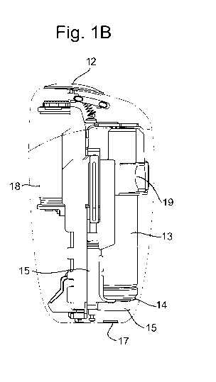
Figure 1B schematically illustrates internal features of the aerosol
generation
device 1 shown in Figure 1A. The housing 11 is made "transparent" in this
figure
(illustrated using dashed lines) in order to show the internal features. On
the right of
the figure, a battery 13 is located within the housing, and a vent point 14 in
an outer
surface of the battery is labelled. In this embodiment, the battery 13 is held
by a
frame 15 and the frame includes a fluid directing arrangement 16 configured to
define a fluid flow path from the vent point 14 to a vent hole 17 in the
opposing end
of the housing 11.
The frame 15 may be configured as a battery support frame positioned
across an internal volume of the housing so as to seal the battery 13 in one
portion
of the internal volume of the housing. For example, in Figure 1B the frame 15
is
arranged along an elongate direction of the aerosol generation device 1
between the
mouth end and opposing end to divide the internal volume of the housing 11
along
at least part of its elongate length. The battery 13 is positioned aligned
along the
elongate direction on one side of the frame 15. The frame 15 may cooperate
together with a mounting cap (shown in subsequent figures) in order to define
this
division of the internal volume. The frame may comprise PA (Polyamide) and/or
PEEK (Polyether ether ketone).
As also shown in Figure 1B, the aerosol generation device 1 of this
embodiment also comprises a heater sub-assembly 18. The heater sub-assembly
18 is arranged in communication with the access means 12. The heater sub-
assembly comprises a heater and a heating chamber with an opening at the mouth
end of the body. The heating chamber is arranged to receive a consumable
aerosol
substrate to be heated in order to generate an aerosol. The packaged aerosol
substrate is input to the heating chamber through the access means 12. The
heater
sub-assembly 18 also comprises a heater for heating the heating chamber, which
may be, for example, a film-type heater wrapped around the heating chamber or
a
CA 03147220 2022-01-12
WO 2021/023890 PCT/EP2020/072326
8
blade-type heater protruding into the heating chamber. In other embodiments,
the
heating chamber may be replaced by a heating coil in which a liquid aerosol
substrate can be heated to generate an aerosol provided at an access means 12
that has a fixed mouthpiece. The heater sub-assembly 18 may also comprise a
temperature sensor for regulating a temperature in the heating chamber.
Furthermore, as shown in Figure 1B, the aerosol generation device 1 of this
embodiment comprises a vibrator element 19. The vibrator element is positioned
within the housing 11, adjacent to an inner surface of the housing, and
arranged to
transmit vibrations to the housing. For example, the vibrator element may be
configured or controlled to vibrate when the heater is initially turned on,
when the
heater reaches a predetermined temperature, or after the heater has been on
for a
predetermined duration. As will be discussed further below, in embodiments
having
a vibrator element 19, the vibrator element may be provided in a variety of
positions
including alongside the battery 13 between the mouth end and the opposing end
as
shown in Figure 1B, or between the battery 13 and the opposing end of the
housing
11.
Figures 2A, 2B and 20 schematically show a first embodiment where a
vibrator element 19 is positioned adjacent to an end of the battery 13.
As schematically indicated in Figure 2A, the vent point 14 of the battery 13
also positioned on the same end of the battery 13. A vibrator element support
21 is
configured to hold the vibrator element 19. In this particular embodiment, the
vibrator element 19 has a round flat shape, and the vibrator element support
21
provides a base wall and side wall for an approximately cylindrical volume
occupied
by the vibrator element 19. The vibrator element support 21 also has a gap in
the
side wall through which electrical connections to the vibrator element 19 may
be
formed. The vibrator element support 21 forms part of the fluid directing
arrangement 16 configured to direct a fluid flow path around the vibrator
element 19
from the battery vent point 14 to the housing vent hole 17.
With this arrangement, the flow of a fluid expelled from the battery 13 during
degassing is directed as shown using curved arrows, passing from the battery
vent
point 14, through a cavity 22 within the housing that is adjacent to the
battery vent
point 14 and is configured to receive the fluid expelled from the battery
during
degassing, and then out through the housing vent hole 17.
Figure 2A also shows a fastener 23 for detachably attaching the frame 15 to
the housing 11.
CA 03147220 2022-01-12
WO 2021/023890 PCT/EP2020/072326
9
Figure 2B schematically shows an alternative view of the embodiment of
Figure 2A, where the housing 11 is omitted from the view in order to more
easily
show internal features. The position of the vent hole 17 of the housing is
illustrated
using a circle.
Figure 20 schematically shows a further alternative view of the embodiment
of Figure 2A, where the housing 11 is displayed "transparently" (using dashed
lines)
in order to illustrate the arrangement of cavity 22. Figure 20 also shows a
fluid flow
direction of fluid ejected out through the housing vent hole 17, indicating
that the
fluid flows directly away from the device 1 out of the opposing end. By
directing the
fluid flow out of the opposing end, the device 1 reduces the risk of injury to
a user
because, in normal usage, the user's face would only be expected to be close
to the
mouth end, and the user's hand would only be expected to be around the sides
of
the device between the mouth end and the opposing end, and therefore any
mechanical force or chemical risk associated with the degassing is directed
away
from the expected locations of the user.
Figure 20 also shows an electrical connector 24, which may be a USB
connector, provided at the bottom end to form an electrical connection
external to
the aerosol generation device 1. This electrical connector 24 is for charging
the
battery 13 and/or for controlling the aerosol generation device 1. The
electrical
connector 24 is internally connected to control circuitry mounted on a PCB 25.
The
control circuitry may be used for controlling the heater sub-assembly 18 to
heat the
heating chamber to a predetermined temperature, and may be powered by the
battery 13. The PCB 25 forms part of the enclosure of cavity 22, along with
the
housing 11 and the vibrator element support 21. In other embodiments, the PCB
25
or the electrical connector 24 may be omitted. For example, the battery 13 may
be
removable from the aerosol generation device 1 such the battery can be charged
externally or replaced, and the aerosol generation device 1 does not need to
provide
means for charging the battery 13.
The PCB 25 is arranged along the frame 15. The PCB 25 may further
comprise a plurality of sections connected by one or more flexible portions.
Figures 3A and 3B schematically illustrate a second embodiment that is
similar to the first embodiment except where described differently in the
following.
Referring to Figure 3A, in the second embodiment, a vibrator element 19' is
provided at a location within the aerosol generation device 1 other than
adjacent to
the vent point 14 at the end of the battery 13. In particular, in this
embodiment, a
CA 03147220 2022-01-12
WO 2021/023890 PCT/EP2020/072326
vibrator element 19' is provided between a side surface of the battery 13 and
an
adjacent inner surface of the housing 11. The vibrator element 19' is also
positioned
towards the mouth end along an elongate side of the device. As shown in Figure
3A, the aerosol generation device 1 may comprise a mounting cap 31 for
5 suspending internal parts of the aerosol generation device within the
housing. In
this case, the vibrator element 19' may be provided at least partly between
the side
surface of the battery 13 and the mounting cap 31, as shown in Figure 3A.
The vibrator element 19' may be connected to the PCB 25 via an end section
of the PCB 25 which folds over an end of the battery 13 closer to the mouth
end of
10 the aerosol generation device 1.
Furthermore, in the second embodiment, the vibrator element 19 can be
removed, such that its function is entirely replaced by vibrator element 19'.
Figure
3B illustrates an embodiment where the vibrator element 19 is removed and an
absorbent pad 32 is positioned in its place adjacent to the vent point 14 of
the
battery 13. The absorbent pad 32 may be provided in the fluid flow path
defined by
the fluid directing arrangement. More specifically, in the embodiment shown in
Figure 3B, the vibrator element support 21 which directed fluid flow around
the
vibrator element 19 in Figure 3A is replaced with an annular support 16 that
directs
fluid flow through the annular support, from the vent point 14 of the battery
13 to the
vent hole 17 in the housing 11, and the absorbent pad 32 is positioned within
the
annular support such that the fluid flow at least partially passes through the
absorbent pad. This arrangement of an annular support 16 has the advantage
that
fluid can flow more directly between the vent point 14 and the vent hole 17
and
therefore the fluid can be expelled more rapidly, reducing the risk of
sufficient
pressure building within the housing 11 to cause damage to the aerosol
generation
device 1. The absorbent pad 32 will at least partly absorb and/or slow down
fluid
flowing along the fluid flow path as a result of a degassing event, thereby
reducing
the chemical risk associated with fluid vented from the battery 13 and out
through
the vent hole 17. The absorbent pad may, for example, comprise a porous
material
such as metal (e.g. aluminium) or plastic.
Figure 3B also illustrates several points 33, 33' at which the cavity 22
within
the housing 11 may be sealed in order to prevent fluid flow towards the mouth
end.
This sealing may be achieved by providing an additional frame component
adapted
to fit snugly between the battery 13 and the housing 11 such that, even if
internal
parts are suspended by the mounting cap 31 within the housing 11, fluid cannot
flow
CA 03147220 2022-01-12
WO 2021/023890 PCT/EP2020/072326
11
from the vent point 14 and around the length of the side of the battery 13 to
reach
the mouth end of the aerosol generation device 1.
Turning to Figures 4A and 4B, there are schematically illustrated further
embodiments with alternative shapes for the annular support 16.
In Figure 4A, the annular support 16' comprises a complete ring at an end
adjacent to the battery 13 and the vent point 14, and the annular support 16'
extends away from the battery 13 to partially enclose an approximately
cylindrical
volume. The annular support 16' has a gap in its wall. As illustrated with
arrows in
Figure 4A, this gap allows fluid to flow away from the most direct path
between the
vent point 14 and the vent hole 17, but the annular support 16' has the
advantage
that it can be constructed from a vibrator element support 21 of the first
embodiment
as shown in Figure 2B, by removing the base wall of the vibrator element
support
21. For example, the base wall may be removed by drilling through the frame
material. In this embodiment, a hole in the housing 11 for the electrical
connector
24 may act as a secondary vent hole.
On the other hand, in Figure 4B, the annular support 16" does not have a
gap in its wall, which completely surrounds an approximately cylindrical
volume. As
illustrated with arrows in Figure 4B, compared to annular support 16', annular
support 16" is more effective at directing fluid flow from the vent point 14
towards
the vent hole 17. This decreases the chance of damage to the aerosol
generation
device 1 as a result of a fast or large degassing event.
Although omitted from Figures 4A and 4B, annular supports 16' and 16"
optionally support an absorbent pad 32 as described above.
A comparison between Figures 4A and 4B also illustrates some features of
the housing 11 according to the example embodiments shown in the Figures. In
particular, as shown in Figure 4A, there is a gap 41 between the mounting cap
31
and the housing 11. This gap is provided to receive a snap-fit attachment
means of
an access sub-assembly including the upper part of the housing 11 shown in
Figure
1A. Additionally, the housing 11 and frame 15 provide a space 42 where the
heater
sub-assembly 18 is to be held, such that the heater sub-assembly 18, the frame
15
and the battery 13 all extend along an elongate direction of the aerosol
generation
device 1.
Additionally, as shown in Figure 4B, even when arranged in an alternative
position provided between a side surface of the battery 13 and an adjacent
inner
surface of the housing 11, the vibrator element 19' may be provided with a
vibrator
CA 03147220 2022-01-12
WO 2021/023890 PCT/EP2020/072326
12
element support 43. In the embodiment of Figure 4B, the vibrator element
support
43 can act as a sealing point 33' for sealing an end of the cavity 22 in order
to
prevent fluid flow towards the mouth end. In this case, the vibrator element
support
43 conforms to the shape of the battery 13. The vibrator element support 43
can
also function as a baffle positioned between a side surface of the battery 13
and an
adjacent inner surface of the housing 11 to seal the space of cavity 22
between the
battery 13 and the housing 11 and restrict fluid flow towards the mouth end of
the
housing 11. In order to reduce the transfer of vibration from the vibrator
element 19'
to the battery 13, and thereby reduce the risk that the vibration could
stimulate a
degassing or leak event, the vibrator element 19' may be mounted in a rubber
gasket.
In embodiments having vibrator element 19 at the end of the battery 13
rather than vibrator element 19' at the side of the battery 13, a baffle 43
may be
nevertheless provided with a similar configuration to the vibrator element
support 43
described above.
Figures 5A to 5E illustrate alternative absorbent pads 32', 33" which may be
used in the second embodiment.
Figure 5A schematically illustrates an alternative view of a frame 15 having
an annular support 16 (which may, for example, be either of the annular
supports
16' and 16" shown in Figures 4A and 4B) positioned adjacent to the vent point
14 of
the battery 13.
As can also be seen in Figure 5A, in this embodiment, a portion of PCB 25
extends to form a part of the bounding walls of cavity 22. This portion of PCB
25
may be a non-functional dummy PCB portion provided as a wall to protect the
electrical connector 24 and/or other control circuitry from chemical effects
associated with degassing or leaks from the battery 13.
Figure 5B schematically illustrates an absorbent pad 32' that is configured to
fit around a perimeter of the approximately cylindrical volume, but has an
annular
shape that provides an uninhibited fluid flow path in its centre.
Figure 5C schematically illustrates a cross section of the absorbent pad 32'
positioned within the annular support 16 of Figure 5A. This illustrates how
the
annular support 16 together with the absorbent pad 32' define a fluid flow
path from
the vent point 14, where the fluid may flow through the absorbent pad 32' (and
be at
least partly absorbed by the absorbent pad 32') and may also flow through the
uninhibited region in the centre of the absorbent pad 32'.
CA 03147220 2022-01-12
WO 2021/023890 PCT/EP2020/072326
13
Figure 5D schematically illustrates an absorbent pad 32" that is configured to
fit in and fill an approximately cylindrical volume, such that there is no
uninhibited
fluid flow path from the vent point 14 to the vent hole 17, and fluid produced
by a
degassing or leak event at the vent point 14 of the battery 13 must pass
through the
absorbent pad 32" before it can pass out of the aerosol generation device 1.
Figure 5E schematically illustrates a cross section of the absorbent pad 32"
positioned within the annular support 16 of Figure 5A. This illustrates how
the
absorbent pad 32" extends across the internal cross section of the annular
support
16.
Comparing the absorbent pad 32' and the absorbent pad 32", the absorbent
pad 32' may support a higher fluid flow rate of fluid produced from the vent
point 14,
but the absorbent pad 32" may be more effective at damping the effect of a
short or
small degassing or leak event and may be more effective at protecting against
chemical risks associated with a degassing or leak event.
Referring now to Figures 6A and 6B, these Figures illustrate alternative
views of further aspects of the fluid directing arrangement in embodiments of
the
invention.
Figure 6A schematically illustrates the cavity 22 between the vent point 14 of
the battery 13 and the vent hole 17 in one embodiment. The housing 11 and vent
hole 17 in this Figure are made "transparent" as shown using dashed lines, in
order
to illustrate internal features. In this embodiment, the cavity 22 is bounded
by the
housing 11, the surface of the battery 13, the frame 15, and the vibrator
element
support 43. The annular support 16 also bounds the cavity 22 with both of its
inner
and outer surfaces. With this arrangement, the annular support 16 acts as a
fluid
directing arrangement that directs a fluid flow towards the vent hole 17, but
the
remainder of the cavity 22 is available to receive fluid expelled from the
battery
during degassing, in the event that fluid is expelled from the battery 13
faster than it
can be expelled through the vent hole 17.
The vent hole 17 in this embodiment is an approximately circular hole that is
reinforced across its centre with two crossed supporting elements. These
supporting elements are arranged across the vent hole to prevent opposing
edges
of the vent hole from closing. The supporting elements assist the vent hole 17
in
retaining its shape and resisting deformation, for example in the case that
the
housing 11 experiences an external impact. This further helps to ensure that
the
vent hole 17 remains available for releasing degassing or leak events such
that the
CA 03147220 2022-01-12
WO 2021/023890 PCT/EP2020/072326
14
aerosol generation device 1 continues to meet safety requirements against the
effects of degassing or leak events as discussed above. In other embodiments,
the
supporting elements could be omitted or could be replaced with a single
supporting
element across the vent hole in a direction that is at greater risk of
deformation due
to external impact.
In this embodiment, the vibrator element support 43 acting as a baffle
optionally comprises a concave surface facing the cavity 22 and directed
towards
the vent hole 17 in the housing 11. The concave surface may extend between the
battery 13 and an adjacent inner surface of the housing 11 so as to seal the
gap
between the outer surface of the battery 13 and the adjacent inner surface of
the
housing 11. With such a concave surface, when fluid flows towards the vibrator
element support 43 in the cavity 22, the vibrator element support 43 will act
as a
reflector and will redirect the fluid in the opposing direction towards the
vent hole 17.
This concave configuration can smooth the reflection, decreasing the maximum
force applied on the vibrator element support 43 by fluid produced in a
degassing
event, and can decrease the maximum pressure of the fluid as it is reflected
by the
vibrator element support 43, thereby decreasing the chance of damage to the
aerosol generation device 1, especially in the case where a fluid produced by
degassing is potentially explosive at high pressures.
Figure 6B schematically illustrates fluid flow in a further embodiment. In
Figure 6B, the housing 11 is hidden so that the fluid flow can be more easily
seen.
More particularly, in the embodiment of Figure 6B, the aerosol generation
device 1 comprises one or more deflector planes 61 positioned adjacent to the
vent
point 14. As shown using arrows, the deflector planes 61 are configured such
that,
when fluid flows from the vent point 14 toward the vent hole 17, the deflector
planes
61 redirect the fluid away from the vent hole 17 and towards the vibrator
element
support 43 (the baffle). This arrangement increases the distance travelled by
the
fluid before reaching the vent hole 17, and can therefore reduce the velocity
of the
fluid when it passes through the vent hole 17. Additionally, the deflector
plane(s)
may be flexible in order to help to dissipate the energy of the fluid vented
from the
vent point 14. The deflector plane(s) may for example be made of a resilient
metal
sheet. As additionally shown in Figure 6B, the fluid may not be entirely
redirected
towards the vibrator element support 43, and some of the fluid may still flow
more
directly towards the vent hole 17.
CA 03147220 2022-01-12
WO 2021/023890 PCT/EP2020/072326
The deflector plane(s) 61 may be combined with the concave configuration
of the vibrator element support 43 described above for Figure 6A in order to
further
reduce the mechanical force felt by a user holding the aerosol generation
device 1
during a degassing event. The deflector plane(s) 61 may also be combined with
the
5 annular support 16 in order to more precisely define a fluid flow path
from the vent
point to the vent hole. The deflector plane(s) 61, the vibrator element
support 43,
the annular support 16, the housing 11, the battery 13, the frame 15 and the
PCB 25
may all form part of the fluid directing arrangement defining the fluid flow
path.
As with Figures 4A and 4B, the embodiments shown in Figures 6A and 6B
10 may additionally comprise an absorbent pad in the annular support 16.
As a further alternative to the fluid directing arrangements and cavities
described for Figures 6A and 6B, the annular support 16 may instead be
configured
to extend up to, and fit flush against, the housing 11, such that the cavity
22 is
entirely defined within the annular support 16, between the vent point 14 and
the
15 vent hole 17.
Referring now to Figure 7, the housing 11 is illustrated from an exterior view
of the opposing end in an embodiment.
In Figure 7, alternative shapes 17' and 17" are illustrated for the vent hole
17. The vent hole 17 for a typical aerosol generation device 1 has a preferred
size
of 20 mm2 in order to allow fluid produced by a degassing event or leak to be
expelled as fast as it is produced and thereby avoid increasing pressure
inside the
housing 11. Such a preferred size vent hole is labelled 17". However, in cases
where it is necessary to provide a smaller vent hole such as labelled 17', the
previously described support elements of the vent hole 17 can, in addition to
preventing opposing edges of the vent hole 17 from closing, help to prevent
the
edges of the vent hole 17' from being pushed outwards by the force of a
degassing
event.
Figure 7 also illustrates further features of the opposing end. In particular,
the opposing end of the housing 11 comprises a hole 23' adapted to receive and
be
held by the fastener 23, such that the housing 11 is attached to the frame 15.
The
hole 23' may be surrounded by a recessed portion of the external surface of
the
housing 11, such that, when the fastener 23 is in place, the fastener 23 is
flush with,
or below, the external surface.
The opposing end of the housing 11 also comprises a hole 24' for providing
access to the electrical connector 24. The electrical connector 24 may extend
out of
CA 03147220 2022-01-12
WO 2021/023890 PCT/EP2020/072326
16
the aerosol generation device 1 through the hole 24' or may be provided within
the
housing 11 such that a corresponding external connector can be connected.
Alternatively, the electrical connector 24 may comprise flat contacts which,
while
forming an electrical connection, do not form a mechanical connection.
Yet further, the electrical connector 24 may be replaced with a magnetic
connector such as an inductive power transfer element. In such an embodiment,
the hole 24' may be omitted.
Turning to Figures 8A and 8B, these Figures illustrate the feature of a
sticker
on the opposing end.
Referring to Figure 8A, the sticker 8A is shown prior to being attached to the
opposing end on an outer surface of the housing 11. In this embodiment, the
sticker
8A is adapted to fit a recess in the opposing end of the housing 11, where the
recess includes the vent hole 17, the hole 23' for the fastener 23 and the
hole 24' for
the electrical connector 24. The sticker 81 has a corresponding hole 24" for
the
electrical connector 24. The sticker 81 may also include product information
as a
convenient way of providing such information on the housing 11.
Referring to Figure 8B, when the sticker is attached to the opposing end, the
sticker 81 is positioned such that holes 24' and 24" align and the electrical
connector 24 is accessible. On the other hand, the sticker 81 is positioned
over the
vent hole 17 and the hole 23' for the fastener 23. Covering the fastener 23 in
this
way improves safety by making it harder for the uneducated consumer to access
the
interior of the aerosol generation device 1. Covering the vent hole 17 in this
way
also improves safety by protecting and hiding access to the battery 13.
However,
the sticker 81 is attached weakly such that, when internal pressure is applied
during
a degassing event of the battery 13, the sticker 81 will detach and be
displaced to
uncover the vent hole 17 and allow fluid to escape from the aerosol generation
device 1. Alternatively, the sticker 81 may be configured to be sufficiently
weak in
an area aligned with the vent hole that, when internal pressure is applied
during a
degassing event of the battery 13, the sticker 81 in the area covering the
vent hole
17 will break and be displaced to uncover the vent hole 17 and allow fluid to
escape
from the aerosol generation device 1.
Another problem addressed by the present specification is a heating
dissipation from the heater sub-assembly 18 to the battery 13, which
potentially
raises up the temperature of the battery further and in addition to a self-
heating
process, and increases the risk of a degassing event. This is specific to non-
rod
CA 03147220 2022-01-12
WO 2021/023890 PCT/EP2020/072326
17
shaped devices, because in a rod-like device the facing surface between the
battery
and the heating oven is comparatively small as it is being limited by a cross-
section
of the rod casing, and generally corresponds to an end surface of a cylinder
(shape
of the heating oven and the battery). Further, in the rod-like device, the
heating oven
and the battery can be arranged spaced apart on the two opposite ends of the
rod.
Referring to both figures 9 and 10, these both schematically illustrate
example embodiments of the aerosol generating device with solutions to
overcome
the problem of heating dissipation from the heater sub-assembly 18.
In these figures, the aerosol generating device is a pebble-like device, in
which the heater sub-assembly 18 and battery 13 have to be arranged relatively
close to each other, and face each other with a relatively large area due to
being
arranged partly in parallel, although not in direct contact. Thus heat from
the heater
sub-assembly 18 can dissipate to the battery 13 more easily than in a rod-like
device where the battery and heater sub-assembly are arranged end-to-end.
Hence
a solution of thermal insulation around the battery 13 or the heater sub-
assembly 18
is provided.
In figure 9, the proposed solution is to encapsulate the battery 13 with a
thermal insulation sleeve 50. The thermal insulation sleeve is for example
characterized by:
= a very low thermal conductivity of 0.12 W/mK;
= a wall thickness for the sleeve in the range between 5 mm and 10 mm;
= a low volumic mass; and
= optionally, a phase change protection.
The thermal insulation sleeve 50 may comprise a blanket (with fibers) or a
solid porous material made of thermal ceramics. In the present embodiment, the
thermal insulation sleeve 50 is disposed along an inner surface of the battery
compartment, and a sealing piece is disposed between the thermal insulation
sleeve
and battery to seal or block gap and thus prevent pressurized gases or liquid
to flow
to PCBA as described previously. In an alternative embodiment, the thermal
insulation may also be disposed along an outer surface of the battery
compartment.
Figure 10 shows an alternative solution where the thermal insulation sleeve
50 is placed around the heater sub-assembly 18. In another embodiment, the
device
can have both an insulation sleeve to encapsulate the battery 13 and an
insulation
sleeve to encapsulate the heater sub-assembly 18.
CA 03147220 2022-01-12
WO 2021/023890 PCT/EP2020/072326
18
Fig. 11 schematically illustrates an example embodiment comprising an anti-
ejection means 60 configured to retain components ejected from the battery 13
when the battery 13 runs into a thermal runaway state, the anti-ejection means
60
being arranged between the battery 13 and the housing 11 and comprising a
first
material having a mechanical strength able to retain the components ejected
from
the battery. The anti-ejection means 60 in this embodiment may also function
as a
fluid directing arrangement as described above.
When the battery 13 runs into the thermal runaway, direct ejection of battery
components (not shown in Fig. 11) may happen. Components are ejected in a
straight line from their point of ejection with an energy linked in particular
with the
pressure building-up inside the battery, when the latter runs into a thermal
runaway
and vents gases. Ejected components will strike the anti-ejection means 60,
the
latter acting therefore as a shield or a fence. Ejected components will then
either
becoming snared in the anti-ejection means 60 or lose a significant part of
their
momentum such that they no longer be dangerous or harmful for the user.
The first material may be configured to retain components ejected from the
battery 13, when the battery 13 has an internal pressure for example between
1000
KPa (10 bars) to 3000 KPa (30 bars), with a preferred internal pressure of
2500 KPa
(25 bars).
The mechanical strength of the first material may vary depending of the
battery properties, the housing of the device or several device component
properties.
The first material may comprise metallic material, aluminum, stainless steel
or any suitable material having a mechanical strength able to retain the
components
ejected from the battery 13.
The first material may also comprise plastic material or Polypropylene PP.
The first material may also comprise porous material such a metallic or
plastic foam for example.
The anti-ejection means 60 may comprise a ribbon or a ring or an elongated
plate. It may comprise, for example, one or several of the previously
mentioned
structures, either separated or joined together as a single piece.
The elongated plate may cover between 50% to 80% of a face (diameter in
case of cylindrical cell) of the battery 50.
The anti-ejection means 60 may also comprise a net, a mesh or a highly
porous material such as foam for example in order to let the gases vent
through it
CA 03147220 2022-01-12
WO 2021/023890 PCT/EP2020/072326
19
while preventing direct ejection of ejected components coming from the battery
13.
The net, the mesh or the highly porous material such as foam may comprise
metallic, plastic or any suitable material having a sufficient mechanical
strength able
to retain the components ejected from the battery. When the anti-ejection
means
comprise such material, pressurized gases may be vented through the anti-
ejection
means and/or around the anti-ejection means.
Foam comprised in the anti-ejection means 60 may be for example metallic
foam comprising inner cavities forming an inner volume through which gases can
be
vented.
The anti-ejection means 60 may have a U-shaped conformation as depicted
in Fig. 11.
The anti-ejection means 60 may extend over a part of the battery 13, over
the full length of the battery 13 or over one extremity or one corner of the
battery 13.
The anti-ejection means 60 may also extend as an elongated plate or ribbon
on at least one side of the battery 13.
The anti-ejection means 60 may alternatively extend as a cylindrical or
parallelepipedal case over at least a part of the battery 13 or over all the
surface of
the battery.
In one embodiment, the housing 11 further comprises at least one anchor
point allowing to attach and secure the anti-ejection means 60 to the housing
11.
The at least one anchor point is arranged in the inner space of the housing 11
and
may comprise for example a ring, a protrusion or a recess around or in which
the
anti-ejection means 60 extends and is secured for example by a bent section of
the
anti-ejection means 60 or by gluing, thermal sealing, form-fit or any suitable
method.
In yet another embodiment, the at least one anchor point is arranged on a
device frame, on the device structure, on the battery or at any suitable
location of
the device.
As depicted in Fig. 11, anti-ejection means 60 may further comprise at least
one opening 80 configured to vent pressurized gases released by the battery 13
from within the anti-ejection means 60.
The at least one opening 80 may be arranged at any suitable location along
the anti-ejection means 60, for example on the middle, on the extremities or
between these two locations on the anti-ejection means 60.
CA 03147220 2022-01-12
WO 2021/023890 PCT/EP2020/072326
The at least one opening 80 has a size which is smaller than a size of the
components potentially ejected from the battery 13 when the battery runs into
the
thermal runaway state but large enough to allow gas venting.
The at least one opening 80 may be circular or rectangular or of any different
5 suitable geometry.
A surface of the at least one opening 80 may be comprised for example
between 10 mm2 to 120 mm2, with a preferred surface of 30 mm2.
The surface of the at least one opening 80 may depend on the type, the size,
the capacity or the chemistry of the battery 13.
10 In another embodiment, the least one opening 80 may comprise a
combination of several smaller openings arranged on the anti-ejection means
60.
The total surface of the combination of the several smaller openings
arranged on the anti-ejection means 60 may be comprised between 10 mm2 to 120
mm2, with a preferred total surface of 30 mm2.
15 The surface or total surface of the at least one opening 80 may vary
depending of the battery properties, the casing of the device or several
device
component properties.
The at least one opening 80 may be configured to vent pressurized gases
from within the anti-ejection means 60 upon a predetermined gas pressure.
20 The at least one opening 80 may comprise a soft sleeve arranged on
the
opening 80, the soft sleeve comprising for example silicon rubber or thin
aluminum
foil that deforms upon a predetermined gas pressure.
The at least one opening 80 arranged on the anti-ejection means 60 and the
vent hole 17 arranged on the housing 11 may be arranged to face each other to
facilitate gas venting outside the aerosol generating device 1 through the
anti-
ejection means 60 and the housing 11.
The at least one opening 80 arranged on the anti-ejection means 60 and the
vent point 14 of the battery 13 may be arranged to face each other to
facilitate gas
venting.
Definitions and Alternative Embodiments
It will be appreciated from the description above that many features of the
described embodiment perform independent functions with independent benefits.
Therefore the inclusion or omission of each of these independent features from
embodiments of the invention defined in the claims can be independently
chosen.
CA 03147220 2022-01-12
WO 2021/023890 PCT/EP2020/072326
21
In the figures, the vibrator element support 21, and the annular supports 16,
16', 16" define an approximately cylindrical volume with a circular cross-
section, and
the absorbent pads 32, 32', 32" are adapted with a similar circular cross-
section.
However, this need not be the case, and these features may instead have an
elliptical, polygonal, or irregular cross-section. Furthermore, instead of
having solely
an annular shape, the absorbent pad 32' may have additional internal structure
to
increase the surface area of the absorbent pad while also maximising the total
uninhibited cross-section area of the fluid flow path between the vent point
14 and
the vent hole 17.
Where the absorbent pad is configured to provide an uninhibited path
through the annular support, this need not be in the centre of the absorbent
pad.
For example an outside cross section of the absorbent pad may not be conformed
with an internal cross section of the annular support, and may be configured
to
provide a gap between an outer surface of the absorbent pad and an inner
surface
of the annular support. For example, the absorbent pad could be a square pad
and
the annular support could have a circular cross-section, such that only the
corners of
the absorbent pad contact the annular support.
The absorbent pad 32, where present, may be attached to the frame 15
using, for example, an adhesive or a structural retaining element such as a
ridge
which may be at an end of the annular support 16. The absorbent pad 32 may be
permanently attached or may be separable such that the absorbent pad 32 can be
replaced as and when it reaches a limit of its ability to absorb fluid vented
from the
battery.
In the above-described embodiments having an annular support, an
absorbent pad is optionally provided within the annular support. In other
embodiments, an absorbent pad may instead be provided elsewhere in the cavity
22
or may be provided across the vent hole 17 in the housing 11. The absorbent
pad
may, in one example, be provided to fill the cavity 22.
The term "heater" should be understood to mean any device for outputting
thermal energy sufficient to form an aerosol from the aerosol substrate. The
transfer
of heat energy from the heater to the aerosol substrate may be conductive,
convective, radiative or any combination of these means. As non-limiting
examples,
conductive heaters may directly contact and press the aerosol substrate, or
they
may contact a separate component such as the heating chamber which itself
causes
heating of the aerosol substrate by conduction, convection, and/or radiation.
CA 03147220 2022-01-12
WO 2021/023890 PCT/EP2020/072326
22
Heaters may be electrically powered, powered by combustion, or by any
other suitable means. Electrically powered heaters may include resistive track
elements (optionally including insulating packaging), induction heating
systems (e.g.
including an electromagnet and high frequency oscillator), etc. The heater may
be
arranged around the outside of the aerosol substrate, it may penetrate part
way or
fully into the aerosol substrate, or any combination of these. For example,
instead of
the heater of the above-described embodiment, an aerosol generation device may
have a blade-type heater that extends into an aerosol substrate in the heating
chamber.
The term "temperature sensor" is used to describe an element which is
capable of determining an absolute or relative temperature of a part of the
aerosol
generation device 1. This can include thermocouples, thermopiles, thermistors
and
the like. The temperature sensor may be provided as part of another component,
or
it may be a separate component. In some examples, more than one temperature
sensor may be provided, for example to monitor heating of different parts of
the
aerosol generation device 1, e.g. to determine thermal profiles.
Alternatively, in
some examples, no temperature sensor is included; for example, this would be
possible where thermal profiles have already been reliably established and a
temperature can be assumed based on operation of the heater.
Aerosol substrate includes tobacco, for example in dried or cured form, in
some cases with additional ingredients for flavouring or producing a smoother
or
otherwise more pleasurable experience. In some examples, the aerosol substrate
such as tobacco may be treated with a vaporising agent. The vaporising agent
may
improve the generation of vapour from the aerosol substrate. The vaporising
agent
may include, for example, a polyol such as glycerol, or a glycol such as
propylene
glycol. In some cases, the aerosol substrate may contain no tobacco, or even
no
nicotine, but instead may contain naturally or artificially derived
ingredients for
flavouring, volatilisation, improving smoothness, and/or providing other
pleasurable
effects. The aerosol substrate may be provided as a solid or paste type
material in
shredded, pelletised, powdered, granulated, strip or sheet form, optionally a
combination of these. Equally, the aerosol substrate may be a liquid or gel.
Indeed,
some examples may include both solid and liquid/gel parts.
Consequently, the aerosol generation device 1 could equally be referred to
as a "heated tobacco device", a "heat-not-burn tobacco device", a "device for
vaporising tobacco products", and the like, with this being interpreted as a
device
CA 03147220 2022-01-12
WO 2021/023890 PCT/EP2020/072326
23
suitable for achieving these effects. The features disclosed herein are
equally
applicable to devices which are designed to vaporise any aerosol substrate.
The aerosol generation device 1 may be arranged to receive the aerosol
substrate in a pre-packaged substrate carrier. The substrate carrier may
broadly
resemble a cigarette, having a tubular region with an aerosol substrate
arranged in a
suitable manner. Filters, vapour collection regions, cooling regions, and
other
structure may also be included in some designs. An outer layer of paper or
other
flexible planar material such as foil may also be provided, for example to
hold the
aerosol substrate in place, to further the resemblance of a cigarette, etc.
The
substrate carrier may fit within the heating chamber or may be longer than the
heating chamber such that the lid remains open while the aerosol generation
device
1 is provided with the substrate carrier. In such embodiments, the aerosol may
be
provided directly from the substrate carrier which acts as a mouthpiece for
the
aerosol generation device.
As used herein, the term "fluid" shall be construed as generically describing
non-solid materials of the type that are capable of flowing, including, but
not limited
to, liquids, pastes, gels, powders and the like. "Fluidized materials" shall
be
construed accordingly as materials which are inherently, or have been modified
to
behave as, fluids.
Fluidization may include, but is not limited to, powdering,
dissolving in a solvent, gelling, thickening, thinning and the like.
As used herein, the term "volatile" means a substance capable of readily
changing from the solid or liquid state to the gaseous state. As a non-
limiting
example, a volatile substance may be one which has a boiling or sublimation
temperature close to room temperature at ambient pressure. Accordingly
"volatilize"
or "volatilise" shall be construed as meaning to render (a material) volatile
and/or to
cause to evaporate or disperse in vapour.
As used herein, the term "vapour" (or "vapor") means: (i) the form into which
liquids are naturally converted by the action of a sufficient degree of heat;
or (ii)
particles of liquid/moisture that are suspended in the atmosphere and visible
as clouds of steam/smoke; or (iii) a fluid
that fills a space like a gas but, being
below its critical temperature, can be liquefied by pressure alone.
Consistently with this definition the term "vaporise" (or "vaporize") means:
(i) to change, or cause the change into vapour; and (ii) where the particles
change
physical state (i.e. from liquid or solid into the gaseous state).
CA 03147220 2022-01-12
WO 2021/023890 PCT/EP2020/072326
24
As used herein, the term "atomise" (or "atomize") shall mean: (i) to turn (a
substance, especially a liquid) into very small particles or droplets; and
(ii) where the
particles remain in the same physical state (liquid or solid) as they were
prior to
atomization.
As used herein, the term "aerosol" shall mean a system of particles
dispersed in the air or in a gas, such as mist, fog, or smoke. Accordingly the
term "aerosolise" (or "aerosolize") means to make into an aerosol and/or to
disperse as an aerosol. Note
that the meaning of aerosol/aerosolise is
consistent with each of volatilise, atomise and vaporise as defined above. For
the avoidance of doubt, aerosol is used to consistently describe mists or
droplets
comprising atomised, volatilised or vaporised particles. Aerosol also includes
mists or droplets comprising any combination of atomised, volatilised or
vaporised particles.