Note: Descriptions are shown in the official language in which they were submitted.
PILOT ASSEMBLIES AND METHODS FOR ENCLOSED GROUND FLARES
AND ELEVATED FLARE STACKS
FIELD
[0001] The present invention relates to combustion of waste gases in oil and
gas fields
using enclosed ground flares and elevated flare stacks. In particular, it
relates to pilot
assemblies and methods that comprise a fire path tubing for generating a
plurality of flame
segments using a hot surface ignition element, which then ignites fuel/air
mixture in a pilot
assembly nozzle to produce a reliable pilot flame.
BACKGROUND
[0002] Gas flaring is an important unit operation employed during the
exploration,
production and processing of natural gas and oil from oil and gas wells.
Flaring is regulated
by federal and state regulations in the U.S. Flaring is done after an oil/gas
well is drilled
during well production testing until the flow of liquids and gas from the
well, oil and gas
compositions, and pressures are stabilized. Flaring is also done as a safety
measure to
release gas from storage vessels and other process equipment to prevent fire
and explosions
during maintenance and repairs of process units and wells. Finally, flaring is
done during
treatment processes such as oil/water separators, and dehydrators (or
treaters), wherein the
waste gas cannot be efficiently captured. A flare system comprises of a flare
stack, piping
that feed gas to the stack, and an ignition system.
[0003] Natural gas is a byproduct formed during oil extraction from oil wells
and is
typically referred to as wellhead gas. Wellhead gas comprises a mixture of
methane,
ethane, propane, nitrogen, carbon dioxide, and water. In addition, wellhead
gas may
contain varying amounts of sulfur compounds such as hydrogen sulfide. Ignition
of waste
gases in flare stacks is initiated and controlled using a burner management
system (BMS).
The burner management system controls the operation of an igniter. Ignition in
turn could
be achieved by spark ignition or sparldess ignition. Flare stacks require a
pilot flame to
ensure that any waste gases released are burnt efficiently. In the case of
spark ignition, the
sparking tips require periodic cleaning to remove carbon accumulation formed
as a
1
Date Recue/Date Received 2023-04-11
byproduct of combustion. Further, periodic adjustment is required to maintain
the spark
gap between the two electrodes in a spark igniter. Therefore, there is an
increasing interest
in using sparkless ignition for piloted systems.
[0004] Enclosed ground flares (also known as combustors) are used to burn
waste gases
from process plants and oil and gas well sites. At well sites, waste gases may
comprise the
vapor that is periodically released from oil and gas hold tanks in order to
maintain tank
pressure. Ground flares eliminate visible flames, noise and smoke that are
seen in elevated
flare stacks. Enclosed ground flares may comprise a cylindrical combustion
chamber,
which may be refractory lined. Waste gas, often at about 0.5 to 8 ounce per
sq. in. gas
pressure, may be fed to one or more burners disposed near the bottom of the
combustion
chamber and burnt. The combustion chamber conceals the flames from the
burners. Since
flow of waste gas to these burners may be intermittent, a robust pilot
assembly is needed
to light the burners and to ensure that waste gases are destroyed to minimize
environmental
impact. In larger enclosed ground flares, the bottom of the combustion chamber
may be
concealed using structures such as a wind fence that block radiation from the
burners and
also improve air supply and distribution to the burners.
[0005] In elevated flare stacks, flame generators for igniting waste gases in
a pilot line
have been in service for a number of years and sold by companies such as Argo
Flare
Services (United Kingdom) and Hero Flare (Kellyville, OK). Flames may be
generated
using compressed air pilot systems or naturally aspirated systems. In the
compressed air
system, compressed air and fuel gas are metered into a mixer located in a
single pilot tubing
assembly at near grade level. A sparking device located in the pilot nozzle
ignites the fuel
and generates the fire ball. The pilot line is purged with the fuel prior to
ignition. The fire
balls travel to the flare tip and ignites the waste gases. Since the
composition of the waste
gases may change from time to time and requires balancing of air/fuel ratios,
a
supplemental fuel such as propane may be used in the pilot to insure reliable
fireball
generation. Instead of using compressed air, ambient air may be drawn into the
mixer in
the pilot line using a venturi effect caused by the fuel flow. These
commercial systems
generate a spark to ignite the air/fuel mixture and generate the flame front.
As is well
2
Date Recue/Date Received 2023-04-11
known, sparking rods require frequent maintenance. Hero Flare, for example,
provides for
pilots that may be raised and lowered from grade level to allow for
maintenance.
[0006] An alternate to spark ignition is sparkless ignition using hot surface
ignition
(HSI) elements. U.S. Patent Publication No. US2012/0282555 titled "HOT SURFACE
IGNITION ASSEMBLY FOR USE IN PILOTS FOR FLARING INCINERATION, AND
PROCESS BURNERS," describes a combustion chamber for generating a fireball to
ignite
a pilot. Ignition gas (fuel) is introduced to a combustion chamber and draws
air into the
combustion chamber. Fuel and air are mixed and ignited by an HSI element.
Combustion
initiates a flame front, which may travel through a pipe until it ignites
flare gases. This
application does not disclose where the combustion chamber is located in the
single pilot
line assembly. Also, disclosed is a pilot assembly in which the HSI element is
located in
the pilot nozzle near the tip of the flare stack. Pilot fuel flows through a
mixer where the
gas is mixed with air drawn in by the fuel flow. The fuel/air mixture then
reaches the pilot
head (nozzle) where it is ignited by the HSI assembly, which is affixed to a
head. A power
source connected to a junction box provides power to the HSI element.
[0007] The Applicant has tested pilot assemblies that comprise a single pilot
line
assembly in which the HSI element is located in the pilot line nozzle that was
located
proximate to the flare stack tip. In this arrangement, the HSI is also used as
a flame sensor.
Methods for using the HSI element as a flame sensor are disclosed in commonly
owned
U.S. Patent Publication No. U52017/0284669. In this assembly, fuel/air mixture
flows up
the pilot line and ignites upon contact with the energized HSI element. The
durability of
the HSI element, as used in this arrangement, was found to be poor because the
HSI element
was exposed to the extreme heat produced by the pilot flame, and because the
HSI element
was also exposed to weather conditions that caused thermal shock (e.g., caused
by rain
droplets) to the HSI element. The Applicant has also tested pilot assemblies
that comprise
a single pilot line and a spark igniter (in place of the HSI element) located
in the pilot line
nozzle that was positioned proximate to the flare stack tip. This arrangement
was also
plagued with unreliable pilot ignition because the spark igniter was rapidly
covered with
soot from the flare flame that burns rich, and deposits soot and debris on to
the sparker rod
causing a barrier for the spark to ground, which in turn caused the ignition
coil to burn out
3
Date Recue/Date Received 2023-04-11
frequently. Coil burnout results in downtime and increases maintenance cost.
In addition,
well operators also suffer from fines imposed by regulatory agencies because
unburnt gases
are exhausted to the atmosphere when flares are not functioning due to a pilot
failure.
Improved pilot assemblies and methods for operating the same for elevated
flare stacks are
therefore needed.
[0008] Efficient pilot assemblies and methods for enclosed ground flares and
elevated
flare stacks in conjunction with a suitable burner management system are
therefore needed
to improve the efficiency and reduce down time at well sites and other
applications such
as fuel and chemical processing units in refineries and petrochemical plants,
chemical
processing, and landfill gas production units.
BRIEF DISCLOSURE
[0009] The exemplary pilot assembly comprising dual lines, namely, a fire path
tubing
and a pilot tubing as disclosed herein overcomes the deficiencies described
above. The HSI
element in the pilot assembly is disposed in the fire path tubing at a
distance below or away
from the pilot nozzle and is therefore not exposed to atmospheric elements and
extreme
heat generated by the pilot flame in the nozzle. Flame temperature is sensed
using a
thermocouple. The positioning of the thermocouple in the cooler part of the
flame inside
the disclosed pilot nozzle improves the durability of the thermocouple. The
thermocouple
in prior art pilot assemblies for elevated flare stacks, for example in U.S.
Patent Publication
No. US2012/0282555 is attached to the external surface of the pilot nozzle,
which exposes
the thermocouple to extreme heat and results in frequent failure. Changing the
thermocouple is not a trivial task because the pilot nozzle is often located
20 ft. to 100 ft.
from grade level.
[0010] Disclosed in an exemplary pilot assembly for igniting waste gases in
enclosed
ground flares comprising a fire path tubing having an inlet end and an outlet
end and having
a fuel inlet disposed at the inlet end, a pilot tubing having an inlet end and
an outlet end
and having a fuel inlet disposed at the inlet end wherein each of the fire
path tubing and
pilot tubing are characterized by a bend such that the inlet end and outlet
end of each tubing
are not disposed along a straight line, a pilot nozzle configured to receive
the pilot tubing
4
Date Recue/Date Received 2023-04-11
at a first nozzle inlet and the fire path tubing at a second nozzle inlet, and
a hot surface
igniter element (HSI) disposed at a distance away from the nozzle and in fluid
communication with the fire path tubing wherein the tip of the HSI element is
offset
whereby the tip does not extend inside the fire path tubing into the flow path
of the fuel/air
mixture. A plurality of flame segments generated in the fire path tubing by
igniting a first
premixed fuel/air mixture by the HSI element travel through the fire path
tubing and ignites
a second premixed fuel/air mixture entering the nozzle through the pilot
tubing to create a
pilot flame for igniting waste gases. The pilot tubing may be disposed
substantially parallel
to the fire path tubing. The inlet end and outlet end of each tubing may be
disposed
substantially orthogonal to each other. The first and second nozzle inlets may
be disposed
substantially orthogonal to each other. The pilot nozzle may be configured to
receive a
thermocouple to detect the presence of the pilot flame. The nozzle may be
adapted to
receive the thetinocouple through an opening disposed near the first nozzle
inlet and
wherein the tip of the thermocouple is disposed below the midpoint of the
length of the
nozzle. The hot surface igniter element may be cylindrical. The hot surface
igniter element
may be energized using DC voltage. The HSI element tip offset may about 0.8
in. The HSI
element tip may be offset by between about 0.5 in. and about 1.05 in. The
nozzle may be
cylindrical in shape. The nozzle may be made of at least one of Type 304
Stainless Steel,
Type 316 Stainless Steel, and Type 310 Stainless Steel.
100111 An exemplary pilot assembly for enclosed ground flares may further
comprise a
first venturi mixer disposed in the fire path tubing upstream of the HSI
element and a
second venturi mixer disposed in the pilot tubing upstream of the nozzle
wherein the first
and second mixers provide first and second fuel/air mixtures to the fire path
tubing and
pilot tubing respectively. Each of the first and second venturi mixer may
comprise an inlet
end and outlet end disposed opposite to the inlet end, an orifice bracket
adapted to mate
with the inlet end of the mixer and adapted to receive an orifice component
connected to a
fuel supply, a neck region disposed downstream of the inlet end and in fluid
communication
with a throat region, wherein the diameter of the neck region is greater than
the diameter
of the throat region, and, a diverging section disposed between the throat
region and the
outlet end of the mixer, wherein at least 50% of the length of the orifice
component is
Date Recue/Date Received 2023-04-11
enclosed within the walls of the mixer at the inlet end. Each mixer may be
made of at least
one of precipitation-hardened aluminum 6061 alloy, cast iron, Type 304
Stainless Steel,
and cast aluminum.
[0012] In an exemplary pilot assembly for enclosed ground flares, the nozzle
may further
comprise a fuel/air mixture distributing element insert adapted to receive the
outlet end of
the pilot tubing wherein the distributing element comprises a neck region with
a first end
and a second end disposed opposite to the first end wherein the first end is
adapted to
receive the pilot tubing; and a throat region having a first end connected to
the second end
of the neck region and a second end wherein the diameter of the throat region
at the first
end is greater than the diameter of the throat region at the second end, and
wherein fuel/air
mixture flows through the neck region and exits through the second end of the
throat region.
The throat region of the fuel/air mixture distributing element may further
comprise a
plurality of holes disposed below the second end. The diameter of the holes
may be about
0.125 inch.
[0013] Disclosed is an exemplary pilot flame light-off sequence for pilot
assembly for
enclosed ground flares comprising energizing the HSI igniter during an
ignition period,
initiating fuel flow to the pilot assembly and generating a plurality of flame
segments in
the fire path tubing by igniting the fuel/air mixture using the energized HSI
element
wherein the plurality of flame segments enters the nozzle and ignites the
fuel/air mixture
entering the nozzle from the pilot tubing, measuring the change in flame
temperature (AT)
in the nozzle relative to ambient temperature using the thermocouple after an
interval
period; and, if the AT is less than a predetermined set point temperature
shutting of fuel
flow to the pilot assembly and repeating the sequence. The ignition period may
be between
about 8 seconds and 15 seconds. The predetermined set point temperature may be
about
100 C. The interval period may be about 30 seconds. The sequence may further
comprise
the steps of measuring the flame temperature at intervals of about 10 seconds
if AT is above
the predetermined set point temperature, recording a maximum temperature
measured by
the thermocouple, shutting off fuel flow if the flame temperature decreases by
at least 1%
from the maximum temperature, and repeating the light off sequence up to three
times after
which the light-off sequence is terminated if the pilot flame is not sensed.
The maximum
6
Date Recue/Date Received 2023-04-11
temperature may be between about 600 and about 1500 C depending on the
heating
value of the fuel.
[0014] Disclosed is an exemplary pilot assembly for igniting waste gases in an
elevated
flare stack, the pilot assembly comprising a fire path tubing, a pilot tubing,
a pilot nozzle
configured to receive the pilot tubing at a first nozzle inlet and the fire
path tubing at a
second nozzle inlet wherein the first and second nozzle inlets are disposed
substantially
orthogonal to each other, and a hot surface ignition element (HSI) disposed at
a distance
below the second nozzle inlet in fluid communication with the fire path tubing
wherein the
tip of the HSI element is offset whereby the tip of the HSI element does not
extend inside
the fire path tubing into the flow path of the fuel/air mixture and wherein
the HSI element
offset is dependent on the length of the pilot assembly. A plurality of flame
segments
generated in the fire path tubing by igniting a first premixed fuel/air
mixture by the HSI
element travel up the fire path tubing and ignites a second premixed fuel/air
mixture
entering the nozzle through the pilot tubing to create a pilot flame for
igniting waste gases
flowing through the elevated flare stack and. The length of the pilot assembly
may be less
than about 100 in, in which case, the HSI offset may be between about 0.5 in.
and about
1.05 in. The offset may be about 0.8 in. The length of the pilot assembly may
be at least
about 200 in., in which case, the offset may be between about 2.85 in. and
about 3.35 in.
The offset may be about 3.1 in.
[0015] Other features and advantages of the present disclosure will be set
forth, in part,
in the descriptions which follow and the accompanying drawings, wherein the
preferred
aspects of the present disclosure are described and shown, and in part, will
become
apparent to those skilled in the art upon examination of the following
detailed description
taken in conjunction with the accompanying drawings or may be learned by
practice of the
present disclosure.
DRAWINGS
[0016] The foregoing aspects and many of the attendant advantages of this
disclosure
will become more readily appreciated as the same becomes better understood by
reference
7
Date Recue/Date Received 2023-04-11
to the following detailed description, when taken in conjunction with the
accompanying
drawings, wherein:
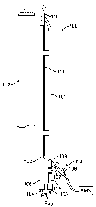
[0017] FIG. 1. Schematic diagram of an exemplary pilot assembly for elevated
flare
stacks.
[0018] FIGS. 2A-E depict (A) perspective view of an exemplary nozzle for a
pilot
assembly, (B) cross sectional view of nozzle, (C) cross sectional side view of
nozzle, (D)
cross sectional side view of nozzle insert and (E) bottom view of insert,
respectively.
[0019] FIGS. 3A-C depict (A) a perspective view of an exemplary fuel/air
mixer, (B)
cross sectional side view of an exemplary fuel/air mixer, and (C)side view and
front view
of an exemplary orifice bracket of the mixer, respectively.
[0020] FIG. 3D depicts perspective view of an exemplary fuel/air mixer (top)
and prior
art mixer (bottom).
[0021] FIG. 3E depicts a front view of another exemplary orifice bracket.
[0022] FIG. 4. Schematic diagram of an exemplary hot surface ignition (HSI)
element.
[0023] FIG. 5. Schematic diagram of an exemplary pilot assembly for elevated
flare
stacks with a spark igniter.
[0024] FIG. 6. Schematic diagram of an exemplary pilot assembly for enclosed
ground
flares
[0025] FIG. 7. Schematic diagram showing exemplary HSI element offset in an
exemplary pilot assembly.
[0026] FIGS. 8A-B. Schematic diagram of another exemplary pilot assembly for
enclosed ground flares.
[0027] FIG. 9. Schematic diagram of an exemplary pilot assembly assembled in
an
enclosed ground flare combustion chamber
[0028] FIG. 10. Schematic diagram of another exemplary pilot assembly for
elevated
ground flares.
8
Date Recue/Date Received 2023-04-11
[0029] The following detailed description includes references to the
accompanying
drawings, which form a part of the detailed description. The drawings show, by
way of
illustration, specific embodiments in which the pilot assembly and methods may
be
practiced. These embodiments, which are to be understood as "examples" or
"options," are
described in enough detail to enable those skilled in the art to practice the
present invention.
The embodiments may be combined, other embodiments may be utilized, or
structural or
logical changes may be made without departing from the scope of the invention.
[0030] In this document, the terms "a" or "an" are used to include one or more
than one,
and the term "or" is used to refer to a nonexclusive "or" unless otherwise
indicated. In
addition, it is to be understood that the phraseology or terminology employed
herein, and
not otherwise defined, is for the purpose of description only and not of
limitation. For
construing the scope of the term "about," the error bounds associated with the
values
(dimensions, operating conditions etc.) disclosed is 10% of the values
indicated in this
disclosure. The error bounds associated with the values disclosed as
percentages is 10%
of the percentages indicated. The word "substantially" used before a specific
word includes
the meanings "considerable in extent to that which is specified," and "largely
but not
wholly that which is specified."
DETAILED DISCLOSURE
[0031] Particular aspects of the invention are described below in considerable
detail for
the purpose for illustrating its principles and operation. However, various
modifications
may be made, and the scope of the invention is not limited to the exemplary
aspects
described.
[0032] FIG. 1 illustrates various features of an exemplary pilot assembly 100
for use in
elevated flare stacks. The assembly comprises a plurality of tubings, namely,
a fire path
tubing 101 and a pilot tubing 102 that are preferably disposed substantially
parallel to each
other. The tubings are generally 3/4 in. pipe having outer diameter of about
1.05 in. and
made of Type 304 Stainless Steel. Tubings made of other alloys such as Type
316 Stainless
Steel, Inconel, and the like may be used. The pilot assembly in turn is
disposed substantially
parallel to a flare stack 112. The pilot assembly may be between about 2 ft.
and about 20
9
Date Recue/Date Received 2023-04-11
ft. in length, as measured from nozzle end 211 (FIG. 2C) to fuel inlet 103 or
104 and may
be elevated using suitable mechanisms to the desired height from grade level
such that pilot
nozzle is positioned substantially proximate to the flare stack tip.
Preferably, pilot nozzle
110 is about level with the flare stack tip. Flare stacks vary in height and
may be 5 to 50 ft.
in height and could even exceed 100 ft. in height. Fuel to the pilot assembly
is typically
off-gas from treatment units such as water/oil separators. Water/oil
separators may be
physical separators or heater treaters. The fuel is typically dehydrated and
fed to the pilot
assembly at a pressure of about 10 psig to 14 psig. Waste gases from oil
storage or water
storage tanks at well sites may vary in composition and are available at low
pressure (about
0.5 to 8 ounce per sq. in.). Waste gases are combusted. Because of varying gas
composition
and low pressures, waste gases are generally not suitable to be used as a fuel
in pilot
systems.
[0033] The fuel to the pilot assembly is split into two streams and fed to
fuel inlet orifice
component 104 in the fire path tubing and to fuel inlet orifice component 103
in the pilot
tubing. Splitting of fuel flow to the pilot tubing and the fire path tubing in
a desired ratio is
achieved by selecting the orifice sizes. Preferably, 70% of the fuel feed is
routed to the
pilot tubing. To achieve this split the size of orifice component 104 may be
about 0.040 in.
and that of orifice component 103 may be about 0.025 in. Orifice components
103 and 104
and disposed at the bottom end (inlet end) of mixers 105 and 106 respectively.
In each
mixer, fuel is premixed (naturally aspirated) with air as the fuel flows
through the mixer.
[0034] The fuel/air mixture exits mixer 105 in fire path tubing 101, flows
through a
reducer element 107 (typically 3/4 in. x 1/2 in.) and is ignited by hot
surface igniter (HSI)
108. Ignitor 108 may be inserted into fitting 109 (preferably Y-shaped, a T-
fitting may also
be used) connected to tubing 101 and may be sealed using electrical seal-off
cement.
Alternately, igniter 108 may be inserted into an opening provided in the fire
path tubing.
Fitting 109 should be understood to be part of the fire path tubing. The
igniter is preferably
positioned such that tip 405 (FIG. 4) is facing upwards towards nozzle 110 of
the pilot
assembly. The tip of the HSI element does not extend inside tubing 101 into
the flow path
of the fuel/air mixture. Instead, it is offset from the wall of the fire path
tubing that receives
the HSI element. If fitting 109 is used, the tip is offset from the vertical
wall (wall of fitting
Date Recue/Date Received 2023-04-11
109 that is substantially parallel to the fire path tubing wall) of fitting
109 that connects to
fire path tubing 101. The offset is preferably less than about 0.75 in. away
from the wall of
the fire path tubing that receives the HSI element (or wall of fitting 109
that is substantially
parallel to the fire path tubing wall). HSI element 108 may be positioned to
be flush with
the wall of the fire path tubing that receives the HSI element. Preferably,
the HSI element
tip is offset about 0.5 in. from the wall of the fire path tubing that
receives the HSI element.
The positioning of the HSI tip as described above does not impede the flow of
fuel/air
mixture in fire path tubing 101. It also generates a plurality of flame
segments by the
ignition of the fuel/air mixture by the energized HSI igniter 108, which
travel up tubing
101 towards nozzle 110. Flame segments comprise one or more flame regions
separated
by one or more slugs of fuel/air mixture that flow up tube 101 towards nozzle
110. When
the igniter 108 is not energized, a continuous flow of fuel/air mixture is
realized in tubing
101. As shown in FIG. 1, igniter 108 is disposed in fire path tubing 101 at a
distance from
nozzle 110. The distance between igniter 108 and nozzle 110 is not a critical
parameter and
may vary depending upon the length of pilot assembly 100.
100351 Igniter 108 comprises an igniter heating element 403 (FIG. 4) that is
substantially
enclosed in a high temperature ceramic body 401. Wires 404 are electrically
connected to
igniter heating element 403 and are used to energize the igniter heating
element using
preferably a DC (direct current) electrical source. A portion of element 403
protrudes from
the ceramic body 401. A high temperature alloy guard (e.g., Inconel guard) 402
protects
the ceramic body, and the exposed part of heating element 403. The Inconel
guard is
preferably 0.4 in. to 0.5 in. in diameter, and more preferably 0.4 in. to 0.45
in. in diameter.
HSI assembly (not including the length of the wires 404) is preferably between
about 2 in.
and about 3 in. in length, and more preferably between about 2 in. and about
2.5 in. in
length. The length of the heating element 403 that protrudes from the ceramic
body 401 is
preferably between about 0.3 in. and about 0.6 in., and more preferably
between about 0.4
in. and about 0.55 in. Ignition wiring 404 connected to the HSI element 108 is
rated to
withstand at least 1000 F. The wiring is routed to a burner management system
(BMS).
When the HSI element is energized, it heats up to 2800 F and ignites fuel/air
mixture to
generate flame segments in tubing 101 as previously described. Reducer 107
increases the
11
Date Recue/Date Received 2023-04-11
velocity of the fuel/air mixture and provides the driving force to push the
flame segments
up tubing 101 and through slotted opening 202 of pilot nozzle 110.
[0036] Exemplary nozzle 110 may be cylindrical in shape (FIG. 2), and
comprises a 1-
1/2 in. Schedule 40 pipe (about 1.85 in. 0.D.) and is preferably fabricated
using at least
one of Type 304 Stainless Steel, Type 316 Stainless Steel, and Type 310
Stainless Steel.
The exemplary nozzle may be between about 5 in. and about 6 in. in length.
Pilot tubing
102 may be removably connected to nozzle 110 at first inlet 201 located at
bottom (inlet)
end 203. Fire path tubing 101 may be connected to nozzle 110 at second inlet
202, which
may be in the form of a slotted opening located on the cylindrical surface 204
of nozzle
110. Inlet 201 is disposed substantially orthogonal relative to inlet 202;
that is, the plane of
inlet 201 and that of 202 are substantially orthogonal to each other. Inlet
202 may be of
various shapes (e.g., oval, cylindrical, rectangular) and is preferably in the
shape of a
slotted opening with radial ends as shown in FIG. 2A. The orthogonal
orientation of the
fire path tubing entry at inlet 202 relative to the pilot tubing entry
prevents rain from
entering the fire path tubing and subjecting the HSI element to thermal shock.
As a result,
the durability of the HSI element may be increased from a few weeks to several
years. Pilot
fuel/air mixture distributing element 205 (FIG. 2D) is inserted into nozzle
110 at inlet end
203 and welded in place. End 206 is adapted to receive pilot line 102, for
example, using
a 3/4 in. NPT threaded connector. Fuel/air mixture flows through neck region
208 of
element 205 and exits through throat region 209 and out of end 207. Neck
region may be
about 0.55 in. in length and about 0.82 in. in diameter, but other suitable
dimensions may
also be used. Throat region 209 may be about 0.45 in. in length and between
about 0.69 in.
to 0.75 in. in diameter at end 207, but other suitable dimensions may also be
used. The
velocity of the fuel/air mixture exiting from the pilot line 102 increases as
it flows through
throat region 209 and exits at end 207 and may be controlled using a plurality
of openings
210, which are disposed in throat region 209. Openings (or holes) 210 are
preferably about
0.125 in. in diameter, but other suitable dimensions may also be used. The
pilot tubing
fuel/air mixture is then ignited by the flame segments entering slotted
opening 202 of
nozzle 110 and provides a reliable pilot flame exiting at end 211 for the
combustion of
waste gases in the flare stack. End 207 is located less than about 0.1 in. to
0.2 in. below the
12
Date Recue/Date Received 2023-04-11
bottom radial end 214 of inlet 202. It also prevents the extinguishing of the
flame segments
that enter nozzle 110 through slotted opening 202 prior to contacting with the
fuel air
mixture leaving exit 207. A plurality of holes 212, each about 0.375 in. in
diameter, are
also provided on the cylindrical surface of nozzle 110 to draw in air to
stabilize the flame
and to prevent the flame from lifting off the nozzle. The exemplary nozzle as
disclosed
herein is typically rated at 60,000 BTU/h at 10 psig when 1000 BTU/cu. ft.
natural gas is
used as the fuel. This rating is dependent on the fuel gas heating value and
the gas pressure
and is subject to change.
[0037] The presence of the pilot flame is detected using thermocouple (e.g., K
type) 111
that is disposed outside the pilot line. The thermocouple tip enters nozzle
110 through
opening 213, which is preferably drilled after welding insert element 205 in
place at end
203 of nozzle 110. Opening 213 is preferably between about 0.3 in. and 0.35
in. in diameter
and is more preferably about 0.34 in. in diameter. Thermocouple 111 is
positioned such
that the thermocouple tip is located at about 2.25 in. above end 203 of the
nozzle, which
positions the thermocouple tip at approximately below the midpoint of slotted
opening 202
(and approximately below the midpoint of the length of the nozzle). As the
flame segments
from fire path tubing 101 enter through slotted opening 202, it ignites the
fuel/air mixture
flowing out through insert 205. The thermocouple therefore senses the
temperature of the
cooler portion of the flame front that generally extends from openings 210 to
below the
mid-point of slotted opening 202, which is relatively cooler than the
adiabatic flame
temperature. The measured temperature is typically between about 1000 F and
1500 F
depending on heating value of the natural gas fuel. Typical flame temperature
when
measured on the outside surface of the nozzle or when measured upstream of the
midpoint
of slotted opening 202 ranges from 1600 F to 2500 F depending upon the
heating value
of the natural gas fuel. The thermocouple positioning in exemplary nozzle 110
permits the
detection of the pilot flame in nozzle 110 while increasing the durability of
the
thermocouple. Thermocouple wiring 113 may be directly connected to the BMS or
may be
routed to the BMS through the casing of igniter 108 as shown in FIG. 1. The
thermocouple
tip may also enter through an opening similar to openings 212 on the
cylindrical surface of
the nozzle 110, such that the tip is positioned at approximately below the
midpoint of
13
Date Recue/Date Received 2023-04-11
slotted opening 202. In this case, a portion of the thermocouple near the
nozzle entry point
would be bent and then positioned to run parallel to the pilot tubing.
[0038] In an alternate embodiment, the thermocouple tip may also be positioned
on the
outside surface of nozzle 110 below the midpoint of slotted opening 202. The
tip may be
inserted in a thermowell suitable affixed by welding or other means to the
outer surface of
the nozzle to protect the tip from atmospheric conditions (wind, rain etc.).
[0039] In an exemplary pilot flame light-off sequence for pilot assembly 100,
the
sequence is started by energizing the HSI igniter 108 over an ignition period.
The ignition
period is preferably between about 8 seconds and about 15 seconds. Igniter 108
is
preferably using a DC voltage of about 12 volts to about 24 volts. The HSI
igniter
temperature rapidly increases to auto-ignition temperature of the fuel. The
burner
management system (BMS) then initiates fuel flow to pilot assembly 100. Upon
ignition
of the fuel/air mixture exiting from mixer 105, a plurality of flame segments
is produced
in fire path tubing 101, which travel up tubing 101, enter nozzle 110 through
slotted
opening 202, and ignites the pilot tubing fuel/air mixture exiting element 205
in nozzle
110. After an interval period, the BMS measures the change in flame
temperature (AT) in
nozzle 110 relative to ambient temperature using the signal from thermocouple
111.
Preferably the interval period is about 30 seconds. A AT value above a
predetermined set
point temperature indicates the presence of a pilot flame in nozzle 110. The
predetermined
temperature (set point) is preferably about 100 C. The values of AT, ignition
period, and
interval period as indicated above are provided as examples only and other
suitable values
may be utilized and fall within the scope of the disclosed method. If AT is
less than the
predetermined set point temperature, ignition of the pilot fuel/air mixture
failed to occur in
nozzle 110. The BMS shuts off the fuel flow to the pilot assembly and the
light-off
sequence is repeated again. If ignition was successful, the BMS monitors flame
temperature at intervals of about 10 seconds. A maximum temperature measured
by the
thermocouple is recorded. The pilot flame temperature typically levels off at
1000 F to
1500 F (maximum temperature) depending on the heating value of the fuel. A
decrease in
temperature by at least 1% of maximum temperature indicates the absence of a
flame. The
BMS then shuts off fuel flow and the sequence is repeated again up to three
times. The
14
Date Recue/Date Received 2023-04-11
BMS shuts off the fuel to the pilot assembly if a pilot flame is not sensed.
Once a stable
pilot flame is sensed by the BMS, ignitor 108 remains in a de-energized state.
In this state,
fuel/air mixture continues to flow through fire path tubing 101. A solenoid
valve (not
shown) may be optionally installed upstream or downstream of mixer 105 to cut-
off fuel
flow to the fire-path tubing after a reliable pilot flame has been
established. The solenoid
valve may be turned ON/OFF by the BMS and minimizes use of fuel in the pilot
assembly.
[0040] The HSI igniter may comprise of durable, high temperature materials
such as
silicon carbide or silicon nitride. HSI assemblies are available from sources
that include,
but are not limited to, Robertshaw, Honeywell, and the like. These igniters
may be
energized using 12 to 24 VDC or 120 to 280 VAC. A burner management system
(BMS)
as disclosed in U.S. Application No. 11/047,794 titled "METHOD, APPARATUS AND
SYSTEM FOR CONTROLLING A GAS-FIRED HEATER", may be adapted to control
the operation of pilot assembly 100.
[0041] Fuel is pre-mixed with air in mixers 105 and 106 (shown as 300 in FIG.
3) located
in fire path tubing 101 upstream of the HSI element and pilot tubing 102
upstream of the
nozzle respectively. Exemplary mixers 105 and 106 are venturi type mixers and
may be
fabricated using at least one of precipitation-hardened aluminum 6061 alloy,
cast iron,
Type 304 Stainless Steel and cast aluminum. A venturi gas mixer uses
Bernoulli's principle
in a converging-diverging nozzle and converts the pressure energy of a motive
fluid (fuel
in this case) to velocity energy at the throat to create a low-pressure zone.
This low-pressure
zone draws in and entrains the suction fluid (air) into a mixing chamber where
it mixes
with the fuel. The gas mixture that leaves mixer 300 typically comprises of 10
parts air and
1-part natural gas. As shown in FIG. 3, mixer 300 comprises a venturi
component 301, and
an orifice bracket 302 that is adapted to mate with inlet end 303 of venturi
component 301.
The length of mixer 300 between inlet end 303 and outlet end 308 is less than
about 10 in.
and is preferably between about 5 in. and about 6 in. Orifice bracket 302 may
be press-fit
into end 303 of component 301 enabled by grooves 310 which may contain a high
temperature permanent epoxy adhesive. Orifice bracket 302 may also be adapted
to be
welded or screwed on to component 301. Orifice components (103 or 104, FIG. 1)
are
connected to threaded connection 304 (e.g., 1/4 in. NPT). As shown in FIG. 3C,
the orifice
Date Recue/Date Received 2023-04-11
bracket may provide for a plurality of air inlets 305. Alternately, as shown
in FIG. 3E,
orifice bracket 302 may provide a threaded connection 304 for receiving an
orifice
component and comprise opposing arms 311 on either side of connection 304 that
slide
into grooves provided at inlet end 303 to create the plurality of air inlets
305. When
installed in fire path tubing 101, fuel enters the mixer 105 (generally shown
as 300 in FIG.
3) through the orifice component 103 that is preferably removably connected to
threaded
opening 304, enters chamber (neck region) 306 and flows through throat 307,
diverging
section 309, and exits through outlet end 308 into fire path tubing 101. Mixer
106 performs
the same function for fuel feed into pilot tubing 102. As the fuel flows
through throat 307,
it draws in air through the plurality of air inlets 305. The ratio of the
throat area to the fuel
inlet area (At/Af) generally controls the pressure loss through the venturi
mixer. At/Af > 0.6
is desired to minimize pressure loss. In exemplary mixer 300, At/Af is about
1. Further, as
shown in Fig 3D, wall 306(a) of mixer 300 at inlet end 303 is in the form of a
skirt (flared
out) such that it encloses at least 50% of the length the orifice component.
The length of
orifice component (e.g., 103, 104) is about 2 in. When the orifice component
is installed in
mixer 300 at connection 304, it extends out of end 303 by about 0.8 inch. This
ensures that
wind does not shear-off the orifice component, especially when the pilot
assembly is
located at 50 ft. or more above grade level. In contrast, as shown in the
prior art mixer 320
in Fig 3D, orifice component enters through hole 321, passes through opening
322 which
is exposed to ambient conditions and then connects to the mixer at screwed
connection
323. The orifice component in mixer 320 is therefore substantially exposed to
ambient
conditions and is susceptible to shearing-off during windy conditions.
Breakage or
shearing-off of the orifice component will stop fuel flow to the pilot
assembly and cause
flame out.
[0042] The BMS may also be used to measure the resistance of HSI element 108
to
check the health of the HSI element. Aging of the resistance wires may occur
at high
temperatures, due to cyclic operation, and possibly due to some carbon
formation. The
resistance of the HSI element is also a function of the age of the HSI
element. Aging
generally causes an increase in the resistance of the HSI element. The
resistance of a fresh
HSI element is about 2 ohms, and more typically between 1.6 and 2.4 ohms at a
reference
16
Date Recue/Date Received 2023-04-11
temperature of 50 C. An aged igniter element is characterized by a resistance
of about 4.5
ohms at a reference temperature of 50 C. An increase in measured resistance
at a reference
temperature would suggest that the heating element is aging. As a remedial
measure, the
energizing voltage to the HSI element may be increased in steps of about 0.5
volts (when
DC voltage is used) to compensate for the aging of the heating element.
Increasing the
energizing voltage is warranted if the measured resistance at a reference
temperature
exceeds the baseline resistance by more than 50%, and preferably by more than
75% to
compensate for ageing of the hot igniter surface assembly. If this action
fails, replacement
of the HSI element would be required. The control methods in the burner
management
system can also keep track of the service time of the HSI element and increase
resistance
accordingly to offset the effects of aging to achieve a predetermined ignition
temperature.
[0043] Alternately, instead of using an HSI element 108, flame segments in the
fire path
tubing of exemplary pilot assembly 500 may be generated using a spark igniter
504 (FIG.
5). Similar to pilot assembly 100, pilot assembly comprises fire path tubing
501 and pilot
tubing 502. The tips of the spark igniter may be installed in the air/fuel
mixture path
flowing through the fire path tubing that is disposed substantially parallel
to pilot tubing
502. The spark igniter wiring and thermocouple 511 wiring 513 are routed to a
BMS that
is adapted to control a spark ignition pilot assembly. Mixers 505 and 506 and
nozzle 510
of pilot assembly 500 may be substantially similar those previously described
for use in
pilot assembly 100. Spark igniters generally require frequent maintenance to
remove soot
build up and/or to adjust the gap between the rods. The pilot assembly with a
spark igniter
would require to be periodically lowered to grade level for checking the gap
between the
sparking rod tips.
[0044] In an exemplary pilot flame light-off sequence for pilot assembly 500,
the
sequence is started by energizing the spark igniter 504. Igniter 504 is
preferably energized
using a DC voltage of about 12 volts to about 24 volts. The burner management
system
(BMS) then initiates fuel flow to pilot assembly 500. Upon ignition of the
fuel/air mixture
exiting from mixer 505, a plurality of flame segments is produced in fire path
tubing 501,
which travel up tubing 501, enter nozzle 510 and ignites the pilot tubing
fuel/air mixture
in nozzle 510. After an interval period, the BMS measures the change in flame
temperature
17
Date Recue/Date Received 2023-04-11
(AT) in nozzle 510 relative to ambient temperature using the signal from
thermocouple
511. Preferably the interval period is about 30 seconds. A AT value above a
predetermined
set point temperature indicates the presence of a pilot flame in nozzle 510.
The
predetermined temperature (set point) is preferably about 100 C. The values
of AT and
interval period as indicated above are provided as examples only and other
suitable values
may be utilized and fall within the scope of the disclosed method. If measured
AT is less
than the predetermined set point temperature, ignition of the pilot fuel/air
mixture failed to
occur in nozzle 510. The BMS shuts off the fuel flow to the pilot assembly and
the light-
off sequence is repeated again. If ignition was successful, the BMS monitors
flame
temperature at intervals of about 10 seconds. The pilot flame temperature
typically levels
off at 1000 F to 1500 F depending on the heating value of the fuel. A
decrease in
temperature by at least 1% of maximum temperature indicates the absence of a
flame. The
BMS then shuts off fuel flow and the sequence is repeated again up to three
times. The
BMS shuts off the fuel to the pilot assembly if a pilot flame is not sensed.
Once a stable
pilot flame is sensed by the BMS, ignitor 504 remains in a de-energized state.
In this state,
fuel/air mixture continues to flow through fire path tubing 501. A solenoid
valve (not
shown) may be optionally installed upstream of mixer 505 to cut-off fuel flow
to the fire-
path tubing after a reliable pilot flame has been established. This solenoid
valve may be
turned ON/OFF by the BMS and minimizes use of fuel in the pilot assembly.
[0045] In another exemplary pilot assembly, the fire path tubing and the pilot
tubing in
the pilot assembly may be arranged as concentric tubes. In one embodiment of
this pilot
assembly, the pilot tubing may comprise the inner tubing and fire path tubing
may comprise
the outer tubing in the concentric arrangement. In another embodiment, the
inner tube may
comprise the fire path tubing, which would be protected from ambient
conditions by the
outer pilot tubing. Various options to connect the outlet end of the pilot
tubing and the
outlet end of the fire path tubing to the pilot nozzle are within the scope of
this disclosure.
Preferably, the fire path tubing entry into the nozzle is substantially
orthogonal to the pilot
tubing entry into the nozzle as previously described. The exemplary nozzle and
mixer
designs may be utilized in this exemplary pilot assembly.
18
Date Recue/Date Received 2023-04-11
[0046] Further, the exemplary pilot systems disclosed above may be modified
for use in
combustors or enclosed ground flares. An exemplary pilot assembly 600 (FIG. 6)
for use
in enclosed ground flares, may comprise fire path tubing 601 and pilot tubing
602 that are
disposed substantially parallel to each other. The tubings may be generally
3/4 in. pipe and
made of Type 304 Stainless Steel. Tubings made of other alloys such as Type
316 Stainless
Steel, Inconel, and the like may be used. The fuel to the pilot assembly is
split into two
streams and fed to fuel inlet orifice component 604 fluidly connected to fire
path tubing
and to fuel inlet orifice component 605 fluidly connected to the pilot tubing.
Splitting of
fuel flow to the pilot tubing and the fire path tubing in a desired ratio is
achieved by
selecting different orifice sizes. Preferably, 70% of the fuel feed is routed
to the pilot
tubing. To achieve this split the size of orifice component 604 may be about
0.040 in. and
that of orifice component 605 may be about 0.025 in. Orifice components 604
and 605 are
disposed at the bottom end (inlet end) of mixers 606 and 607 respectively. In
each mixer,
fuel is premixed (naturally aspirated) with air as the fuel flows through the
mixer.
Downstream of the mixers, fire path tubing 601 and pilot tubing 602 are bent
such that the
sections of each tubing upstream and downstream of the bend portions 608 and
608' are
disposed substantially orthogonal to each other. Fuel filters (Y strainers)
609 and 609' may
be disposed upstream of the bend components or fittings to serve as flame
arrestors and to
prevent the flame segments from propagating back and escaping out of mixers
606 and
607. Fittings such as the orifice component, mixer, flame arrestors, bend
components
(connectors) disposed in each of the fire path tubing 601 and pilot tubing 602
may be
considered to be part of the fire path tubing and pilot tubing, respectively.
Similarly, HSI
housing fitting 611 may be considered to be part of the fire path tubing.
[0047] Pilot assembly 600 may be between about 2 ft. and about 5 ft. in length
as
measured from the tip of nozzle 603 to the fuel supply inlet at the entry of
the pilot
assembly. Fuel to the pilot assembly may be off-gas from treatment units such
as water/oil
separators. Water/oil separators may be physical separators or heater
treaters. The fuel is
typically dehydrated and fed to the pilot assembly at a pressure of about 10
psig to 14 psig.
Waste gases from oil storage or water storage tanks at well sites may vary in
composition
and are available at low pressure (about 0.5 to 8 ounce per sq. in.). Waste
gases are flared
19
Date Recue/Date Received 2023-04-11
or combusted in the enclosed ground flares. Because of varying gas composition
and low
pressures, waste gases are generally not suitable to be used as a fuel in
pilot systems. The
fuel/air mixture exits mixer 606 in fire path tubing 601 and is ignited by a
hot surface
igniter (HSI) 610 (FIG. 7) disposed in fitting 611. Ignitor 610 may be
inserted into fitting
611, which may be, a T-shaped or Y-shaped fitting or a suitable combination of
fittings
fluidly connected to tubing 601 and may be sealed to fitting 611 using
electrical seal-off
cement that allows wiring 618 to pass through. Alternately, igniter 610 may be
inserted
into a suitable opening provided in fire path tubing 601. Igniter 610 is
preferably positioned
such that tip 612 does not extend inside tubing 601 into the flow path of the
fuel/air mixture.
As shown on FIG. 7, tip 612 is offset from the wall of the fire path tubing
that receives the
HSI element and subsequently from the flow path of the fuel/air mixture. Tip
612 may be
offset from the wall or from the face of fitting 611 that is substantially
parallel to the fire
path tubing wall that connects to fire path tubing 601. The offset may be
about 0.8 in. from
the wall of the fire path tubing that receives the HSI element. The offset may
be between
about 0.5 in. and about 1.05 in. The positioning of the HSI tip as described
above does not
impede the flow of fuel/air mixture in fire path tubing 601. It also generates
a plurality of
flame segments by the ignition of the fuel/air mixture by energized HSI
igniter 610, which
travel through tubing 601 towards exit 614 fluidly connected to nozzle 603.
Flame
segments comprise one or more flame regions separated by one or more slugs of
fuel/air
mixture that flow through tubing 601 and towards nozzle 603. When igniter 610
is not
energized, a continuous flow of fuel/air mixture is realized in tubing 601. By
off-setting
the HSI tip as described above, the tip stays at ignition temperature even
when fuel-air
mixture is flowing through fire path tubing 601 without getting quenched. Off-
setting the
HSI tip also protects the HSI tip from the extreme flame temperatures of the
flame
segments that would reduce HSI durability and require replacing the HSI
element within
months. Pilot assemblies with the HSI igniter tip located in the fuel-air
mixture flow path
are unreliable as flame segment generators, because the HSI tip will be
quenched by the
cooler fuel-air gas mixture. Placing the HSI tip in the fuel-air gas flow
would reduce the
ignition temperature to below the practical ignition point and cause a misfire
that would
Date Recue/Date Received 2023-04-11
allow natural gas to escape without being burnt into the atmosphere emitting
methane into
the atmosphere and violate environmental regulations.
[0048] Details related to exemplary igniter 610 were previously disclosed
(FIG. 4).
Details related to exemplary nozzle 603 were previously disclosed (FIGS. 2A-
E). Pilot
tubing 602 may be removably connected to nozzle 603 at first inlet 613. Fire
path tubing
601 may be connected to nozzle 603 at second inlet 614, which may be in the
form of a
slotted opening located on the cylindrical surface nozzle 603. Inlet 613 may
be disposed
substantially orthogonal relative to inlet 614. The pilot tubing fuel/air
mixture is ignited by
the flame segments entering slotted opening 614 of nozzle 603 and provides a
reliable pilot
flame exiting from nozzle 603. Fire path tubing 601 and pilot tubing 602
downstream of
HSI igniter fitting 611 then pass-through suitable holes provided in plate or
gasket 615
(FIGS. 8A-B) and into the combustion section of ground flare 616 (FIG. 9). The
pilot flame
exiting from nozzle 603 ignites the waste gas entering ground flare 616
through waste gas
pipe 617 as the waste gas exit the burners provided in the combustion section
of ground
flare 616. Waste gas pipe 617 may be a 3 in. pipe. Plate 615 may be in the
form of a flange
and configured to form a seal with the combustion section opening in ground
flare 616
using suitable gaskets and the like. Plate 615 may also be rectangular in
shape depending
on the shape of the combustor section opening (FIG. 10). Depending on the
configuration
of the combustor section in ground flare 616, nozzle 603 may be disposed at an
angle
relative to the longitudinal axes of fire path tubing 601 and pilot tubing 602
(FIG. 10)
downstream of plate 615. The nozzle shown in FIG. 10 may be used if the pilot
assembly
is disposed under the burners in enclosed vertical ground flare 616. Ignition
wiring 618
(FIG. 6) connected to the HSI element 610 may be rated to withstand at least
1000 F.
Wiring 618 may be routed to a burner management system (BMS) through junction
box
619. Details of suitable burner management systems and methods for operating
the
exemplary pilot systems were previously disclosed. When the HSI element is
energized, it
heats up to 2800 F and ignites fuel/air mixture to generate flame segments in
tubing 601.
In FIG. 9, the orientation of the legs or sections of fire path tubing 601 and
pilot tubing 602
when assembled in ground flare 616 are shown to be perpendicular to the ground
621.
Alternate orientations are within the scope of the exemplary pilot system 600
for use in
21
Date Recue/Date Received 2023-04-11
enclosed gas flares. For example, assembly 600 may be rotated such the fire
path tubing
601, pilot tubing 602 and HSI housing component 611 are disposed parallel to
the ground.
[0049] The presence of the pilot flame may be detected using thermocouple
(e.g., K
type) 620 that is disposed outside pilot line 602 and enters the bottom of
nozzle 603 (FIG.
8B) and is positioned such that the thermocouple tip is disposed to sense the
temperature
of the cooler portion of the flame as previously disclosed (FIG. 2A and
related description),
which is relatively cooler than the adiabatic flame temperature. The
thermocouple
positioning in exemplary nozzle 603 permits the detection of the pilot flame
in nozzle 603
while increasing the durability of the thermocouple. Thermocouple 620 may also
be routed
to a suitable BMS through junction box (or conduit) 619. The thermocouple tip
may also
enter through an opening on the cylindrical surface of the nozzle 603. In this
case, a section
or part of the thermocouple near the nozzle entry point would be bent and then
positioned
to be disposed parallel to the pilot tubing. Fuel flow into fire path tubing
601 and pilot
tubing 602 is pre-mixed with air in mixers 606 and 607 (shown as 300 in FIG. 3
and related
description) respectively, located in fire path tubing 601 upstream of the HSI
element and
pilot tubing 602 upstream of nozzle 603 respectively. Exemplary mixers 606 and
607 may
be venturi type mixers and may be fabricated using at least one of
precipitation-hardened
aluminum 6061 alloy, cast iron, Type 304 Stainless Steel and cast aluminum.
[0050] The pilot assemblies for elevated flare stacks disclosed herein are
intended for
igniting well site off gases to meet U.S. EPA 0000a regulations. The pilot
assemblies are
located at an elevation of typically between about 10 ft and 50 ft. The
exemplary pilot
assemblies disclosed and claimed herein permit reliable light-off of the pilot
and for the
pilot flame to stay lit thereby permitting oil and gas production companies to
reduce their
greenhouse gas emissions and meet the EPA's guidelines on reducing emissions.
Furthermore, a key requirement of EPA 0000a regulation is recording the
temperature
profile of the pilot assembly to produce a temperature chart for inspection to
show that the
pilot remained lit during operation. The exemplary pilot assembly and nozzle
and BMS
systems and methods disclosed herein provides for the temperature measurements
required
to meet EPA 0000a regulations. The placement of the thermocouple tip in nozzle
603 as
22
Date Recue/Date Received 2023-04-11
disclosed above protects the thermocouple from the extreme temperatures that
would cause
premature failure of the thermocouple.
[0051] The length of exemplary pilot assemblies for elevated flare stacks may
be
between about 2 ft. and about 20 ft. as generally measured from the nozzle tip
to the fuel
supply inlet point. The length of exemplary pilot assemblies for enclosed
ground flares
may be between about 2 ft. and about 5 ft. For exemplary pilot assemblies less
that about
8 ft. (96 in.) in length, the HSI element tip offset may be about 0.8 in. The
HSI element tip
may be offset by between about 0.5 in. and about 1.05 in. Without being bound
by any
particular theory, for exemplary pilot assemblies that exceed about 16 ft.
(200 in.) in length,
the HSI element tip offset may be about 3.1 in. The HSI element tip may be
offset by
between about 2.85 in. and about 3.35 in. By off-setting the HSI tip, as
described above,
the tip stays at ignition temperature even when fuel-air mixture is flowing
through the fire
path tubing of the pilot assembly without getting quenched. Off-setting the
HSI tip also
protects the HSI tip from the extreme flame temperatures of the flame segments
that would
reduce HSI durability and require replacing the HSI element within months.
Pilot
assemblies with the HSI igniter tip located in the fuel-air mixture flow path
are unreliable
as flame segment generators, because the HSI tip will be quenched by the
cooler fuel-air
gas mixture. Placing the HSI tip in the fuel-air gas flow reduces the ignition
temperature
to below the practical ignition point and causes a misfire that would allow
natural gas to
escape without being burnt into the atmosphere emitting methane into the
atmosphere and
violate environmental regulations.
[0052] Exemplary pilot assembly 600 for use in enclosed ground flares may be
about 30
in. in length. Exemplary pilot assembly 100 for elevated flare stacks may be
at least about
72 in. (6 ft.) in length for use in elevated flare stacks that are between
about 20 ft. and 60
ft. in height. Some elevated flare stacks may produce higher amounts of
radiant heat, which
would require the tubing fittings (e.g., fuel/air mixers, reducer components
and the like),
HSI connector, and wiring to be lowered to above ground level (grade), which
in turn
would increase the length of the pilot assembly to 8 ft. or more. Pilot
assemblies of length
of about 200 in. (16 ft. to 17 ft.) to be used with 20 ft. elevated flare
stacks may be required
to enable maintenance to be carried out at ground level to avoid costs
associated with lift
23
Date Recue/Date Received 2023-04-11
equipment for maintenance technicians and also to increase personnel safety
during rain
and high wind conditions.
[0053] The exemplary pilot assemblies and pilot nozzles disclosed herein
significantly
simpler in design compared to the pilot assembly disclosed in U.S. Pat. No.
6,840,761 titled
"ULTRA-STABLE FLARE PILOT AND METHODS." Unlike pilot (26) and windshield
(48) disclosed in U.S. Pat. 6,840,761, the exemplary pilot assemblies
disclosed herein, do
not incorporate flame stabilizer (44), baffles (64, 66), vertical wall (58),
and a variety of
holes (58, 60, 68, 78). The exemplary pilot assemblies described herein may be
used in
elevated flare stacks that exceed 100 ft. in height. Nozzle 110 comprises
insert 205 as
previously described to distribute the flame such that the flame propagates
through the
length of nozzle 110. The pilot assembly is capable of staying lit during high
wind and rain.
The nozzle is between about 5 in. and about 6 in. in length and the
cylindrical nozzle design
shields the flame from cross winds. Further, since the fuel to the pilot
assembly is at fed at
a pressure of about 10 psig and 14 psig, the fuel velocity through the
exemplary pilot
assemblies assists with flame stability even during high wind conditions.
During heavy
rain, water droplets that enter nozzle 110 may drain through pilot tubing 102
and through
openings 305 in mixer 306. Fire path tubing 101 may be gently bent before
being fluidly
connected to the cylindrical surface of nozzle 110 at an entry point that is
substantially
orthogonal to the entry point of pilot tubing 102 (FIG. 2A, 8B). As a result,
rainwater is
substantially prevented from entering fire path tubing 101.
[0054] Exemplary pilot system 600 may also be used as a pilot in the
combustion section
of process vessel burners. In process vessels, reliable and efficient
sparkless igniters for
treating and processing oil and gas produced at well sites are needed. Crude
oil is often
extracted from oil wells as an oil-water emulsion that may also contain
significant amounts
of free water and natural gas. Gas is separated from the oil-water emulsion
and free water
using a gas separator. Free water may be removed using water knock-out
vessels, which
are also known as phase separators. The resulting oil-water emulsion, with
minimal
amounts of gas and free water, may be sent to process vessels such as treaters
(also referred
to as heater treaters) to separate water from the emulsion. The treater
dehydrates or
dewaters the produced crude oil to a required basic sediment and water (BS&W)
level. Oil-
24
Date Recue/Date Received 2023-04-11
water separation may be enhanced by heating, adding emulsion breaking
chemicals,
coalescing media, and/or electrostatic fields. Most crude oils are treated to
a range of 0.2%
to 3.0% BS&W as determined by the ASTM Standard Test No. D96-82. Treaters
typically
contain water knock-out and de-gassing zones to produce crude oil of desired
quality.
Heating lowers the viscosity of the oil making it easier for the water to
settle. It also aids
in the coalescing of the water droplets, which facilitates water removal.
Heater treaters are
used where the emulsion cannot be broken using just retention, quiescence, and
chemical
de-emulsifiers. The fuel to the pilot igniter in process vessels at well sites
may be natural
gas. Natural gas is a byproduct formed during oil extraction from oil wells
and is typically
referred to as wellhead gas. Wellhead gas comprises a mixture of methane,
ethane, propane,
nitrogen, carbon dioxide, and water. Efficient operation of the treater
depends on efficient
igniter performance. Igniter performance depends on many factors including
igniter design,
durability of ignition elements, and proper adjustment of fuel gas pressure,
which in turn
controls fuel and air flow rates to the igniter. Ignition may be accomplished
with spark
igniters or sparkless igniters. In the case of spark ignition, the sparking
tips require periodic
cleaning to remove carbon accumulation foimed as a byproduct of combustion.
Further,
periodic adjustment is required to maintain the spark gap between the two
electrodes in a
spark igniter. Therefore, there is an increasing interest in using sparkless
ignition in treater
burners.
[0055] The Abstract is provided to allow the reader to determine quickly from
a cursory
inspection the nature and gist of the technical disclosure.
[0056] Although the present disclosure has been described in connection with
the
preferred form of practicing it, those of ordinary skill in the art will
understand that many
modifications can be made thereto without departing from the spirit of the
present
disclosure. Accordingly, it is not intended that the scope of the disclosure
in any way be
limited by the above description.
[0057] It should also be understood that a variety of changes may be made
without
departing from the essence of the disclosure. Such changes are also implicitly
included in
the description. They still fall within the scope of this disclosure. It
should be understood
Date Recue/Date Received 2023-04-11
that this disclosure is intended to yield a patent covering numerous aspects
of the disclosure
both independently and as an overall system and in both method and apparatus
modes.
[0058] Further, each of the various elements of the disclosure and claims may
also be
achieved in a variety of manners. This disclosure should be understood to
encompass each
such variation, be it a variation of an implementation of any apparatus
implementation, a
method or process implementation, or even merely a variation of any element of
these.
[0059] Particularly, it should be understood that the words for each element
may be
expressed by equivalent apparatus terms or method terms - even if only the
function or
result is the same. Such equivalent, broader, or even more generic terms
should be
considered to be encompassed in the description of each element or action.
Such terms can
be substituted where desired to make explicit the implicitly broad coverage to
which this
disclosure is entitled. It should be understood that all actions may be
expressed as a means
for taking that action or as an element which causes that action. Similarly,
each physical
element disclosed should be understood to encompass a disclosure of the action
which that
physical element facilitates.
[0060] In addition, as to each term used it should be understood that unless
its utilization
in this application is inconsistent with such interpretation, common
dictionary definitions
should be understood as incorporated for each term and all definitions,
alternative terms,
and synonyms such as contained in at least one of a standard technical
dictionary
recognized by artisans and the Random House Webster's Unabridged Dictionary,
latest
edition.
[0061] Further, the use of the transitional phrase "comprising" is used to
maintain the
"open-end" claims herein, according to traditional claim interpretation. Thus,
unless the
context requires otherwise, it should be understood that variations such as
"comprises" or
"comprising," are intended to imply the inclusion of a stated element or step
or group of
elements or steps, but not the exclusion of any other element or step or group
of elements
or steps. Such terms should be interpreted in their most expansive forms so as
to afford the
applicant the broadest coverage legally permissible.
26
Date Recue/Date Received 2023-04-11