Note: Descriptions are shown in the official language in which they were submitted.
i
Cutting machine with blade depth adjustment
The invention relates to a cutting machine with a cutting support for material
to be
cut, with a vertically movable blade bar which bears a blade for cutting the
cut
material located thereon, with a cutting drive for vertically moving the blade
bar
and with a blade depth adjustment for vertically adjusting the blade bar
relative to
a vertically movable drive element of the cutting drive.
Cutting machines generally have a mechanical structure which moves a blade
manually by the action of force by the operator or electrically driven from
top to
bottom through a material to be cut, such as for example a paper stack. A
cutting
counter support in the form of a cutting strip is required as a counterpart to
the
blade. This cutting strip is generally inserted flush with the table surface
of the
cutting machine on which the material to be cut is located. Since the blade is
also
__ designed to separate the lowermost layer of a cut material stack, the blade
has to
penetrate minimally into the cutting strip. The cutting strip is generally
produced
from plastics; this provides, on the one hand, sufficient strength as the
cutting
counter support and, on the other hand, permits the blade to be able to
penetrate
minimally into the cutting strip without being damaged. The cutting strip and
the
__ blade are subjected to a certain degree of wear during the cutting process
so that
both have to be replaced at regular intervals in order to ensure their
function.
On the one hand, it has to be ensured that the lowermost layer of a cut
material
stack is also cut through, but on the other hand the blade and the cutting
strip are
designed to be protected in the best possible manner in order to achieve
service
lives which are as long as possible. This reduces the operating costs and is
also
desirable for reasons of saving resources. It is thus very important for the
blade to
penetrate into the cutting strip only just as far as is absolutely necessary.
If the
blade and/or the cutting strip are worn, they have to be replaced.
To this end, screws are screwed into the blade through the vertically movable
blade bar of the cutting machine. These screws are guided in a vertically-
displaceable manner in slots (elongated holes) in the blade bar. The fastening
takes place at the lower reversal point of the blade movement, wherein the
slots
Date Recue/Date Received 2022-02-04
2
permit an approximate adaptation of the position of the blade to the cutting
strip
before the screws are tightened. Thus whilst during the cutting cycle the
blade is in
its lowermost movement position on the cutting strip, it does not penetrate
therein.
The fine adjustment of the blade which is thus required relative to the
cutting strip
is undertaken with a so-called blade depth adjustment. This blade depth
adjustment has to be able to be carried out with fine-tuning in order to
permit the
operator to adjust the optimal penetration depth of the blade in the cutting
strip in a
simple manner. In order to ensure that, on the one hand, the lowermost
position of
a cut material stack is reliably cut but that, on the other hand, the blade
and the
cutting strip are protected to a maximum extent, the adjustment has to be
carried
out very accurately. Since both the blade and the cutting strip are
successively
worn during their period of use, they have to be occasionally re-adjusted
until they
are replaced.
Solutions available today to the operator are often difficult to handle since
the
adjusting elements of the blade depth adjustment are not located on the front
face,
the main working region of the cutting machine, but for example at the side.
This is
a drawback, in particular, when the accessibility is limited at this point due
to the
point of installation of the cutting machine. Machines are also available on
the
market in which the adjustment is located in the machine interior behind a
housing
cover. This housing cover has to be removed for the adjustment. In addition to
the
additional effort, therefore, often the accessibility to an adjusting element
of the
blade depth adjustment is also limited. Although other embodiments are located
in
the main working region of the machine, the adjustment is not implemented by a
central adjustment option but a plurality of adjusting elements have to be
actuated
or adjusted relative to one another in order to achieve the desired effect.
Generally
tools are required for the adjustment process. If these tools are required for
no
other function of the machine, this involves additional costs for the machine
user,
in particular when these tools are special tools. In the case of wear or loss,
these
tools may then be generally purchased only as a replacement part from the
machine manufacturer.
Date Recue/Date Received 2022-02-04
3
Accordingly, it is the object of the present invention to develop the blade
depth
adjustment in a cutting machine of the type mentioned in the introduction such
that
an operator may implement the blade depth in a manner which is as rapid,
simple,
fine-tuned and ergonomically advantageous as possible.
This object is achieved according to the invention in that the blade depth
adjustment has a deflection lever which is pivotably mounted about a
horizontal
axis on the blade bar, the drive element being articulated thereon at a first
radial
distance, as well as an adjusting mechanism acting on the deflection lever at
a
second radial distance to the horizontal axis, for rotating and fixing the
deflection
lever.
According to the invention, the shortening or lengthening of the vertical
distance
between the drive element (for example the drive connecting rod) and blade bar
is
carried out by means of a rotatable deflection lever, the vertical position of
the
drive element relative to the blade bar being able to be changed by the
rotation
thereof.
Preferably, the small adjustment path required on the blade should be
transferred
into a larger adjustment path on the adjusting element. To this end, for
example,
the second radial distance may be greater than the first radial distance, in
particular at least double the size of the first radial distance. To this end,
the point
of action of the drive element on the deflection lever may also be arranged
horizontally offset relative to the horizontal axis, and on the deflection
lever in an
angular range relative to the horizontal plane defined by the horizontal axis
of the
deflection lever, of +/- 600 about the horizontal axis.
In a particularly advantageous embodiment of the invention, the adjusting
mechanism has a transmission lever which is articulated at one end on the
deflection lever and at the other end is supported on the blade bar. The
transmission lever permits the displacement of the adjusting mechanism in the
directly accessible main working region of the cutting machine. In this case,
advantageously the transmission lever may be articulated at the other end
eccentrically on an adjusting element which is rotatably mounted on the blade
bar.
Date Recue/Date Received 2022-02-04
4
Preferably, the adjusting element may have a tool receiver with a non-circular
receiving contour in order to rotate the adjusting element by means of a tool,
in
particular with single-handed operation. This tool may preferably also be used
when changing the blade. Further preferably, the adjusting element has a
toothed
ring which is arranged coaxially to the axis of rotation thereof and the blade
bar
has at least one tooth, or vice versa, wherein the toothed ring and the at
least one
tooth are in engagement with one another in order to fix the adjusting element
in
the rotational position thereof. For rotating the adjusting element, the
adjusting
__ element preferably may be axially displaceable between a first position in
which
the toothed ring and the at least one tooth are in engagement with one
another,
and a second position in which the toothed ring and the at least one tooth are
not
in engagement with one another and the adjusting element may be rotated. Thus,
on the one hand, the torque which is introduced via the transmission lever is
.. received and, on the other hand, the operator may undertake the adjustment
in a
smooth manner.
Preferably, a spring-loaded latch is arranged on the blade bar, said latch in
each
case being latched progressively from one tooth gap to the next tooth gap of
the
toothed ring, when rotating the adjusting element, in order to provide the
operator
with a direct visual and/or haptic feedback during the adjustment.
Alternatively or
additionally, the adjusting element may have a scale following the rotational
direction thereof and the blade bar has a marking cooperating with the scale,
or
vice versa, in order to provide the operator with an orientation aid for the
adjustment.
Further advantages of the invention emerge from the description and the
drawing.
The aforementioned features described in more detail below according to the
invention in each case may also be used individually per se or in a plurality
of
combinations thereof. The embodiments shown and described are not to be
understood as a definitive list but rather have an exemplary nature for
explaining
the invention.
Date Recue/Date Received 2022-02-04
5
The invention is shown in the drawings and is described in more detail with
reference to an exemplary embodiment. In the drawings:
Fig. 1 shows the front view of the cutting machine according to the
invention with a blade depth adjustment;
Fig. 2 shows an adjusting mechanism of the blade depth adjustment
corresponding toll in Fig. 1;
Figs. 3a, 3b show views from above of the adjusting mechanism, wherein an
adjusting element of the adjusting mechanism in Fig. 3a is shown
in a rotationally blocked state and in Fig. 3b in a rotationally non-
blocked state; and
Fig. 4 shows a detailed view of a latching mechanism for the
adjusting
element.
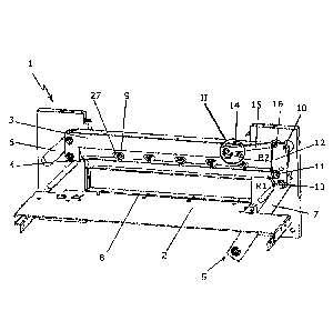
The cutting machine 1 shown in Fig. 1 comprises a cutting support 2 for the
material to be cut, a vertically movable blade bar 3 which bears a blade 4 for
cutting the cut material located thereon, and a cutting drive 5 for vertically
moving
the blade bar 3. The blade bar 3 is mounted in a vertically movable manner in
a
guide slot 6 running obliquely in this case. The cutting drive 5 is manually
actuated
or electrically driven and is motion-coupled to the blade bar 3 via a
vertically
movable drive connecting rod 7, the lower reversal point thereof defining the
lower
reversal point of the blade movement.
A cutting strip 8 which is generally inserted flush in the cutting support 2
serves as
a counterpart for the blade cutter. Since the blade 4 is also designed to
separate
the lowermost layer of a cut material stack, the blade 4 has to penetrate
minimally
into the cutting strip 8. The cutting strip 8 is generally produced from
plastics; this
provides, on the one hand, sufficient strength as the cutting counter support
and,
on the other hand, permits the blade 4 to penetrate minimally into the cutting
strip
8, without being damaged itself. The cutting strip 8 and the blade 4 are
subjected
to a certain degree of wear during the cutting process, such that from time to
time
they both have to be replaced in order to fulfil their function optimally.
Thus, on the
one hand, it has to be ensured that even the lowermost layer is cut through
and,
on the other hand, the blade 4 and the cutting strip 8 are protected in the
best
Date Recue/Date Received 2022-02-04
6
possible manner in order to achieve service lives which are as long as
possible.
Thus it is very important for the blade 4 to penetrate into the cutting strip
8 only
just as far as is absolutely necessary.
If the blade 4 and the/or the cutting strip 8 are worn, they have to be
replaced. To
this end, screws 9 are screwed into the blade 4 through the blade bar 3, said
screws being guided in a vertically adjustable manner in slots (elongated
holes) 27
in the blade bar 3. The fastening takes place at the lower reversal point of
the
blade movement, i.e. at the lower reversal point of the drive connecting rod
7,
wherein the slots 27 permit an approximate adaptation of the position of the
blade
to the cutting strip 8 before the screws 9 are tightened. Thus whilst during
the
cutting cycle the blade 4 is located in its lowermost movement position on the
cutting strip 8, it does not penetrate therein.
The required fine adjustment of the blade edge relative to the cutting strip
8, i.e.
the vertical adjustment of the blade bar 3 relative to the lower reversal
point of the
drive connecting rod 7, is undertaken with a blade depth adjustment 10. This
blade
depth adjustment 10 comprises a deflection lever 12 which is pivotably mounted
on the blade bar 3 about a horizontal axis in the form of a horizontal bearing
pin
II, on which the drive connecting rod 7 is articulated at a radial distance R1
to the
bearing pin 11 by means of a connecting rod pin 13, as well as an adjusting
mechanism 14 acting on the deflection lever 12 at a radial distance R2
relative to
the bearing pin 11 for rotating and fixing the deflection lever 12.
Preferably, the
radial distance R2 as shown in Fig. 1 is greater than the radial distance R1.
The
connecting rod pin 13 is arranged on the deflection lever 12 both horizontally
offset
relative to the bearing pin 11 and in an angular range, relative to the
horizontal
plane defined by the bearing pin 11, of ca. +/- 60 about the bearing pin 11.
The adjusting mechanism 14 has a transmission lever 15 which is articulated at
one end by means of a lever pin 16 on the deflection lever 12 and, as shown in
Fig. 2, is rotatably mounted at the other end eccentrically on an adjusting
element
17 which in turn at 18 is rotatably mounted on the blade bar 3. To this end, a
bearing pin 19 is eccentrically fastened to the adjusting element 17, about
which
the transmission lever 15 is rotatably mounted. The adjusting element 17 also
has
Date Recue/Date Received 2022-02-04
7
an (outer) toothed ring 20 arranged coaxially to the axis of rotation 18
thereof. By
means of a screw 21 a fixing element 22 with a plurality of teeth 23 is
screwed
onto the blade bar 3, said teeth being engaged with the toothed ring 20 and
thus
fixing the adjusting element 17 in the rotational position thereof. The
bearing pin
19 has a tool receiver 24 with a non-circular, in this case hexagonal,
receiving
contour.
The adjusting element 17 is axially displaceable between a first position
(Fig. 3a)
in which the toothed ring 20 and the teeth 23 are in engagement with one
another,
and a second position (Fig. 3b) in which the teeth 23 and the toothed ring 20
are
not in engagement with one another and thus the adjusting element 17 may be
rotated. The adjusting element 17 is displaceable from the first position into
the
second position counter the action of a restoring spring 25. As shown in Fig.
4,
optionally a spring-loaded latch 26 is arranged on the blade bar 3, said latch
in
each case being latched progressively from one tooth gap to the next tooth gap
of
the toothed ring 20, when rotating the adjusting element 17.
The functional sequence of the cutting process is as follows:
The drive connecting rod 7 is connected, on the one hand, to the components of
the cutting drive 5, not shown, such as for example a drive crank drive. On
the
other hand, the drive connecting rod 7 is coupled via the connecting rod pin
13 to
the deflection lever 12. If the cutting process is activated by the operator,
the drive
connecting rod 7 is pulled downwardly from its upper resting position into its
lower
reverse position. Since the cutting bar 3 is connected in turn via the bearing
pin 11
to the deflection lever 12, the blade 4 follows this downward movement along
the
guide slot 6 in which the blade bar 3 is mounted. The cut material placed
below
the blade 4 is cut through by the blade 4, wherein the cutting strip 8 serves
as the
cutting counter support. After the step of cutting the material to be cut has
taken
place, the entire subassembly travels back into its upper end position.
The functional sequence of the blade depth adjustment is as follows:
Date Recue/Date Received 2022-02-04
8
After the blade 4 and/or the cutting strip 8 have been changed, the lower
reversal
point of the blade 4 generally has to be corrected in order to ensure that the
blade
4 penetrates sufficiently far into the cutting strip 8 that even the lowermost
layer of
a cut material stack is still cut through. The cutting drive 5 which is
connected to
the drive connecting rod 7 always performs exactly the same lifting movement
relative to the movement path. When changing the blade 4, this blade is
fastened
to the blade bar 3 at the lower reversal point bearing against the blade strip
8. To
this end, the long holes 27 for the screws 9 are located in the blade bar 3.
So that
the blade 4 minimally penetrates the cutting strip 8, the distance between the
drive
connecting rod 7 and the blade fastening has to be minimally extended. Since
here it is a case of only a few tenths of a millimetre, this is only able to
be achieved
in an unsatisfactory manner by obvious operating principles, such as for
example
a drive connecting rod 7 which may be adjusted in terms of length by means of
a
threaded spindle. Depending on the pitch of the threaded spindle, even with a
small adjustment of the threaded spindle a relatively large change to the
lower
reversal point of the blade 4 is produced. A relatively large adjustment range
for
the operator is designed to bring about only a small displacement of the
reversal
point of the blade 4. This results in the possibility for a fine adjustment.
In order to achieve the desired effect, the drive connecting rod 7 is fastened
in an
articulated manner to the deflection lever 12 which in turn is rotatably
connected
via a bearing pin 11 to the blade bar 4. The arrangement is designed such that
a
rotation of the deflection lever 12 about the bearing pin 11 brings about a
positional change of the connecting rod pin 13. The position of the connecting
rod
pin 13 and thus the point of action of the drive connecting rod 7 determine
the
upper and lower end position of the blade bar 4 and thus of the blade 4 during
the
cutting cycle.
If the lever pin 16 is significantly further away from the bearing pin 11 than
the
connecting rod pin 13 (R2 >> R1), via the relative distances when pivoting the
deflection lever 12 about the bearing pin 11 with a relatively large
positional
change of the lever pin 16 it leads only to a relatively small positional
change of
the connecting rod pin 13. Moreover, the angular positions of the lever pin 16
and
the connecting rod pin 13 on their partial circles around the bearing pin 11
Date Recue/Date Received 2022-02-04
9
determine how much a positional change on the lever pin 16 via the deflection
lever 12 has an effect on the change of the lower reversal point of the blade
4. If
the connecting rod pin 13 in its initial position on a partial circle around
the bearing
pin 11 is arranged perpendicular below the bearing pin 11, a rotation of the
deflection lever 12 by a few angular degrees leads to virtually no change at
the
lower and upper reversal point of the blade 4, since the vertical distance
between
the drive connecting rod 7 and the blade 4 is only minimally changed. If the
connecting rod pin 13 is arranged, however, on the same partial circle in its
initial
position horizontally to the bearing pin 11, a rotation of the deflection
lever 12 by a
few angular degrees leads to a substantially greater change at the lower and
upper reversal point of the blade 4, since the vertical distance between the
drive
connecting rod 7 and the blade 4 changes more sharply ("sine curve effect").
This means that by changing the distances and angular arrangements of the pins
11, 13, 16 to one another the adjustment sensitivity may be changed within a
large
range. Thus it is possible to implement the desired effect that a possibility
for fine
adjustment of the lower reversal point of the blade 4 is provided to the
operator via
a transmission ratio.
In order to permit the operator to adjust the lower blade reversal point at an
ergonomically optimal position in the working region thereof, the deflection
lever
12 is moved via the transmission lever 15. This transmission lever 15, mounted
in
an articulated manner, acts on the lever pin 16 of the deflection lever 12.
The
adjustment mechanism 14 acts at the other end of the transmission lever 15,
said
adjustment mechanism rotating and fixing the deflection lever 12 for the blade
depth adjustment. In order to implement the desired deflection of the
transmission
lever 15 and thus the deflection lever 12, this transmission lever is
eccentrically
fastened in a rotatable manner to the centrally mounted adjusting element 17.
If
the adjusting element 17 is rotated about its central axis, the eccentric
fastening of
the transmission lever 15 to the adjusting element 17 produces the desired
translatory movement of the transmission lever 15 which moves the deflection
lever 12 via the lever pin 16.
Date Recue/Date Received 2022-02-04
10
Often large cutting forces, which the cutting drive 5 has to provide, are
required
when cutting the cut material. These forces act in the entire drive train.
Since the
forces act via the drive connecting rod 7 on the deflection lever 12, a
torque, which
acts via the lever pin 16 on the transmission lever 15, is produced by the
offset of
the connecting rod pin 13 relative to the bearing pin 11. The transmission
lever 15
in turn transmits thereby a translatory force which is converted in turn into
a torque
by the eccentric fastening of the transmission lever 15 to the adjusting
element 17.
This torque causes the adjusting element 17 to be set into a rotational
movement.
The adjusting element 17 is thus designed, on the one hand, to be able to be
rotated easily by the operator for adjusting the blade depth and, on the other
hand,
the adjusting element 17 is not able to be adjusted when cutting the cut
material.
In order to be able to represent both functions, the adjusting element 17 has
the
toothed ring 20 in which the teeth 23 of the fixing element 22 engage. The
adjusting element 17 is thus impeded in its rotational movement and may not be
self-actingly adjusted during the cutting process.
If the operator wishes to adjust the adjusting element 17 for adjusting the
blade
depth, a tool which is kept in the vicinity of the machine is used to this
end. This
tool fits positively in the tool receiver 24 of the bearing pin 19. If the
operator now
pushes with the tool against the adjusting element 17, the adjusting element
17 is
displaced from its rotationally blocked first position against the action of
the
restoring spring 25 into the rotationally non-blocked second position. The
adjusting
element 17 may now be rotated by the operator for the blade depth adjustment
with the above-described effects. After the adjustment has been carried out,
the
operator pulls the tool away and the adjusting element 17 is moved by the
restoring spring 25 back into its first position in which it engages again in
the teeth
23 and thus is blocked in its new rotational position. The blade depth
adjustment,
i.e. the pushing-in and rotating of the adjusting element 17 by means of the
tool, is
thus possible with single-handed operation. Advantageously, the screws 9 may
also be released or tightened by the same tool.
The latch 26 assists the operator specifically in order to adjust or relocate
a
rotational position of the adjusting element 17. The latch 26 enables the
adjusting
element 17 when rotated to be latched into predetermined angular positions so
Date Recue/Date Received 2022-02-04
11
that the operator, for example, may "feel their way" from one latching
position to
the next in order to find the optimal adjustment. Such an adjusting element
latching mechanism also provides the machine manufacturer with the option to
be
able to describe the adjusting process more clearly to the operator, for
example in
the instruction manual, by predetermining how many latching points the
adjusting
element 17 is designed to be rotated by as a basic adjustment. As an
orientation
aid for the adjustment, alternatively the adjusting element 17 may also be
provided
with a scale following the rotational direction thereof and the blade bar 3
may be
provided with a marking on which the respective scale value may be read.
Date Recue/Date Received 2022-02-04