Note: Descriptions are shown in the official language in which they were submitted.
CA 03149338 2022-01-31
1
Method of manufacturing a pressure vessel and pressure vessel
Field of the invention
The invention relates to a method of manufacturing a pressure vessel
and to a respective pressure vessel.
Background of the invention
The market for pressure vessels, in particular pressure vessels
reinforced with fiber composite material, grows continually.
Increasing production of natural gas and fracking gas makes storage
in pressure vessels necessary, especially in countries without a
corresponding pipeline network. In addition, the automotive industry
which is heavily involved in the development of fuel cell vehicles
requires that the fuel be stored in the form of gaseous hydrogen
under high pressure in pressure vessels. Other types of vehicles
using hydrogen may be railway vehicles, aircraft or watercraft. Even
in spacecraft, application is conceivable. As regards the transport
of the pressure vessels, it is desired that they should be light-
weight pressure vessels because transporting heavy-weight pressure
vessels is associated with the consumption of an unnecessarily high
amount of energy, thus leading to excessively high transport costs.
Presently used cylindrical fibre-reinforced pressure vessels have a
reinforcement layer consisting of fibre composite material made of
fibres embedded in a matrix material which is wound onto an inner
vessel (called liner) of the pressure vessel, which acts as a winding
core, by means of a winding method. Winding is the preferred process
for a manufacturing of fibre composite layers which is efficient in
terms of time and costs. While the inner vessel guarantees, for
instance, gas-tightness of the pressure vessel, the reinforcement
layer made of fibre composite material provides the pressure vessel
with the necessary mechanical rigidity. For pressure vessels of
type 3, a metallic inner vessel (metallic liner) consisting e. g.
Date Recue/Date Received 2022-01-31
CA 03149338 2022-01-31
2
of aluminum or steel is employed; in case of pressure vessels of
type 4, the non-load-bearing inner vessel (liner) is made of plastic.
The plastic liners are commonly produced by blow moulding,
rotomoulding or welding of individual components. In particular,
materials can be used which have good permeation properties with
respect to hydrogen, such as polyamides or polyethylenes, in
particular high-density polyethylene. The pressure vessels must
withstand a very high inner pressure.
Currently, for instance,
hydrogen tanks of automobiles are filled at a pressure of
approximately 700 bar. Especially, the pressure vessels may not
burst, even in case of a crash. Therefore, such pressure vessels
are designed with a cylindrical central part closed on both sides
by what are called "pole caps". To compensate for manufacturing
tolerances, the reinforcement layers are accordingly oversized. For
instance, the reinforcement layer can be manufactured with the
filament winding method, wherein the winding of the pressure vessels
takes place in one single operation. In other words, the fibers are
wound in one operation onto the plastic liner circumferentially or
crosswise or in the form of helix layers.
From the German patent application DE 10 2016 222 674 Al, a method
of manufacturing a pressure vessel is known, as well as a pressure
vessel and a pipe extrusion line. The method comprises the following
steps: providing a central portion of the pressure vessel, the
central portion comprising an extruded liner pipe which is at least
partially surrounded by at least one fibre-reinforced layer; joining
the central portion to at least one end portion and applying at least
one fibre-reinforced outer layer, the fibre-reinforced outer layer
extending at least partially over the at least one end portion and
over the central portion.
Furthermore, from the German patent application DE 10 2011 105 627
Al, an assembly method for a composite pressure vessel is known. An
end portion of a tubular element is fitted into an angular slot
formed in an end cap. A sealing means can be positioned in the
annular slot. The end cap comprises an annular groove in an outer
Date Recue/Date Received 2022-01-31
CA 03149338 2022-01-31
3
surface of the end cap body portion. On an outer surface of the
tubular element, a first material layer is formed. This first
material layer comprises a first composite material with fibres
oriented in the circumferential direction with respect to the tubular
element. A second material layer is formed on the first material
layer, with a portion of the second material layer being positioned
in the annular groove, comprising a second composite material which
comprises fibres which are oriented axially with respect to the
tubular element. A third material layer is formed adjacent to the
second material layer and in the annular groove, comprising a third
composite material with fibres which have an orientation in the
circumferential direction with respect to the tubular element.
In addition, from the German patent application DE 31 03 646 Al, a
pressure vessel for storage and transport of gases and gaseous
mixtures under high pressure with a pipe-shaped metal body is known,
the pressure vessel being formed with a dome-shaped end cap at least
on one end. The wall thickness of a pipe section of an aluminum or
aluminum alloy body is reduced with respect to the wall thickness
of the spherical cap(s) and surrounded by a jacket made of fibre-
reinforced, in particular glass-, carbon-, aramid- or boron fibre-
reinforced plastic. The fibres of the jacket should be wrapped
around the aluminum body and create at least partially helical lines
on the latter.
This makes the manufacturing of such pressure vessels elaborate and
expensive.
Therefore, there is a desire to make the production more efficient.
Summary of the invention
The object of the invention is to provide a manufacturing method for
fibre-reinforced type 4 pressure vessels which can be performed more
efficiently and inexpensively than the methods known in the state
of the art, where at least the same requirements are met by the
Date Recue/Date Received 2022-01-31
CA 03149338 2022-01-31
4
pressure vessel. Furthermore, it is an object of the invention to
disclose a corresponding pressure vessel.
The first object is achieved by means of a manufacturing method in
which first a pressure vessel blank, comprising at least one type 4
liner and a cylindrical tube operatively connected to it, is produced
and subsequently a fibre composite material, for instance, is wound
onto the blank.
The term "pressure vessel" comprises all types and shapes of pressure
vessels which comprise an inner vessel, also called liner. Type 4
pressure vessels comprise a liner made of a thermoplastic material
which was reinforced by a fibre composite material on the outside
such that the pressure vessel meets the requirements made in terms
of pressure resistance. As
a rule, these pressure vessels are
cylindrical with convex terminals on both sides of the cylindrical
central part. These terminals are called pole caps and are used for
pressure-tight sealing of the central part. For reinforcement of
the pressure vessel, an outer layer made of fibre composite material
is wound onto the outside of the inner vessel, potentially forming
at the same time the outside of the pressure vessel. The inner
vessel can be produced by means of various techniques, for instance
by welding, injection moulding or as a blow-moulded part. The pole
caps can also be placed onto the central part after production, for
instance by welding. The separate pole caps may be manufactured,
for instance, by injection moulding.
Pressure vessels with a
thermoplastic inner vessel have a very low weight, on the one hand,
which is important e. g. for applications in means of transport; and
on the other hand, content such as hydrogen, for example, can be
stored under high pressure with low losses since suitable
thermoplasts have a sufficiently low hydrogen permeability and the
required rigidity is provided by the outer layer made of fibre
composite material.
In general, a fibre composite material for the fibre composite layer
Date Recue/Date Received 2022-01-31
CA 03149338 2022-01-31
is composed of two main components, which are fibres herein, embedded
in a matrix material which creates the strong bond between the fibres.
Therein, the fibre composite material can be wound from one fibre
or from a plurality of fibres, wherein the fibre(s) is/are wound
closely next to and in contact with each other. The wound fibres are
already impregnated with matrix material. This results in a fibre
layer onto which additional fibres are wound in further fibre layers
until the fibre composite material has the desired thickness and
forms a corresponding fibre layer having this thickness. The outer
layer is wound in several layers made of fibre composite material,
where different layers may contain fibres arranged at different fibre
angles with respect to the cylinder axis of the pressure vessel. In
one embodiment, each of the fibre layers made of first and/or
additional fibres, for instance second fibres, comprises a plurality
of fibre layers. The composite gives the fibre composite material
properties of higher quality, such as higher strength, than any of
the two individual components involved could provide. The
reinforcing effect of the fibres in the fibre direction is achieved
when the modulus of elasticity of the fibres in the longitudinal
direction is in excess of the modulus of elasticity of the matrix
material, when the elongation at break of the matrix material is in
excess of the elongation at break of the fibres and when the breaking
resistance of the fibres is in excess of the breaking resistance of
the matrix material. The fibres that can be used are fibres of any
kind, for example glass fibres, carbon fibres, ceramic fibres, steel
fibres, natural fibres, or synthetic fibres. The matrix materials
used for the fibre composite layer are as a rule duromers. The
material properties of the fibres and the matrix materials are known
to the person skilled in the art, with the result that the person
skilled in the art can select a suitable combination of fibres and
matrix materials for producing the fibre composite material for the
particular application. Herein, individual fibre layers in the fibre
composite region can comprise a single fibre or a plurality of equal
or different fibres.
Date Recue/Date Received 2022-01-31
CA 03149338 2022-01-31
6
The term "thermoplast" designates plastics which can be
thermoplastically deformed within a specific temperature range.
This process is reversible, that is, it can be repeated for an
indefinite number of times by cooling and reheating into the molten
state, provided that no thermal decomposition of the material takes
place due to overheating.
This distinguishes thermoplasts from
duroplasts (or duromers) and elastomers.
Another unique
characteristic of thermoplasts is that they can be welded, in
contrast to, for example, duromers.
The invention proposes to first manufacture a pressure vessel blank.
In this manner, manufacturing of the pressure vessel blank is
separated from manufacturing of the pressure vessel as a whole. Thus,
the pressure vessel blank is produced separately. Here and in the
following, "separate production" designates a production separate
from, in particular in advance of, the actual production of the
pressure vessel. The actual production of the pressure vessel takes
place by winding, for instance, a fibre composite material onto the
pressure vessel blank. By
providing the pressure vessel blank
separately, optimal conditions for production can be ensured,
increasing efficiency and quality of this component and thus of the
entire pressure vessel. Moreover, in this manner, the geometry of
the pressure vessel is only determined by the prefabricated
cylindrical pipes and no longer by the liner, thus increasing
manufacturing precision in terms of length and of the diameter of
the pressure vessel.
In detail, the production method can include the steps of
manufacturing and processing of a pole cap reinforcement,
manufacturing and processing of a cylindrical pipe, installation of
a connecting piece (boss) in the liner, joining the cylindrical pipe
and the pole caps with the liner, fixation of the positions of the
cylindrical pipe and the pole cap reinforcements, for instance by
punctual adhesive bonding, winding helix and circumferential layers
consisting of a fibre composite material over the blank thus produced,
Date Recue/Date Received 2022-01-31
CA 03149338 2022-01-31
7
and curing of the overall system.
In another advantageous embodiment, the cylindrical pipe is
manufactured separately. This allows producing the pipe from various
materials using the manufacturing method optimally suited for the
respective material. In addition, manufacturing of the cylindrical
pipe can be easily automated in this manner, further increasing the
manufacturing efficiency.
In another advantageous embodiment, the cylindrical pipe is wrapped
out of a fibre composite material.
This material can be, for
instance, a carbon fibre reinforced plastic (CFC). Components made
of CFC are lightweight, on the one hand, but they also have a very
high hardness. If the cylindrical pipe is made of a material of the
same group which is later wrapped over the pressure vessel blank,
this entails advantages in connecting the pressure vessel blank with
the layer wrapped over it, increasing the overall hardness of the
pressure vessel. By manufacturing the cylindrical pipe as a fibre
composite component on a separate winding machine, wrapping speed
and the number of fibres wrapped simultaneously can be increased.
In this manner, the cylindrical pipe can also be produced from a
different type of fibre than the rest of the pressure vessel. This
can be an advantage for specific applications. Moreover, the cycle
time of the actual vessel winding machine on which subsequently the
pressure vessel is manufactured by winding the fibres on the pressure
vessel blank, is substantially reduced.
This is especially
advantageous since due to its simple cylindrical geometry, the
cylindrical pipe can be manufactured on a simpler and therefore less
expensive winding machine than the pressure vessel. The pressure
vessel has pole caps over which helical layers must be wrapped,
whereas in one embodiment, the cylindrical pipe can only be produced
by winding circumferential layers. In addition, by manufacturing
the cylindrical pipe separately, different fibre angles can be
introduced into the circumferential layers, or different types of
Date Recue/Date Received 2022-01-31
CA 03149338 2022-01-31
8
fibres with different stiffnesses can be introduced into the product
more easily than with conventional production.
Also, the cylindrical pipe can be manufactured with a lower wall
thickness than the overall vessel, reducing the risk of fibre
waviness and thus increasing resistance of the fibres.
In another advantageous embodiment, the cylindrical pipe is wound
onto a metallic winding core.
Deposition of the fibres can be
performed more precisely on a metallic winding core than on a plastic
liner. Use of the fibres can be improved in this manner. Moreover,
a metallic winding core can be manufactured very precisely, which
also allows a very precise production of the inner diameter of the
cylindrical pipe or cylindrical semi-finished pipe wound thereon.
This results in a reduction of manufacturing tolerances, which can
in turn lead to an increase in the filling volume of the pressure
vessel with equal assembly space.
In another advantageous embodiment, the cylindrical pipe is
manufactured on a long winding core such that one winding results
in several panels. In other words, first a cylindrical semi-finished
pipe is wound from which the cylindrical pipe is cut to length.
Especially if metallic winding cores are used, their hardness allows
the winding of very long cylindrical semi-finished pipes. Winding
of a particularly long cylindrical semi-finished product and cutting
the same to length afterwards to produce metallic pipes further
increases the efficiency of production. However, it is also possible
to manufacture the cylindrical pipe on the winding core to final
dimension by means of "board disks", so that no cutting to length
or other finishing process is necessary.
In another advantageous embodiment, the cylindrical pipe is, at the
most, only partially cured. This makes it easy to handle and to
work it mechanically, and during final curing after winding, it can
produce a substance-to-substance bond with the winding. Here, as a
Date Recue/Date Received 2022-01-31
CA 03149338 2022-01-31
9
rule, use of a partially cured pipe is to be preferred over a
completely cured pipe, use of the latter, however, not being entirely
excluded.
In another embodiment, the cylindrical pipe is extruded. This is a
very economical manufacturing method. By means of extrusion, in
particular, very long semi-finished pipes can be produced from which
correspondingly cylindrical pipes can be cut to length. Especially
long fibre-reinforced materials as well as duroplastic materials,
however, cannot be extruded, such that for extrusion e.g. short
fiber-reinforced thermoplasts, such as fibre-reinforced polyamides,
can be used which, however, may entail disadvantages with respect
to wrapped pipes in terms of hardness.
In another embodiment, the cylindrical pipe is pultruded. With
pultrusion, materials can be processed which have longer fibres,
even up to continuous fibres, than materials which can be processed
with the extrusion method. Due to the longer fibres, the hardness
of pipes thus manufactured with respect to extruded pipes can be
increased.
In another advantageous embodiment, the liner has an outer geometry
for receiving the cylindrical pipe such that the cylindrical pipe
can positively engage with the liner. Especially if this positive
engagement takes place at the transition from the cylindrical part
of the pressure vessel to the pole caps, in particular if the pole
caps have pole cap reinforcements, problems during cold filling can
be avoided. If positive engagement takes place only on one side of
the pressure vessel, the cylindrical pipe can be pushed onto the
liner from the other side. If the outer geometry of the liner has
a recess the cylindrical pipe can rest in, that is, if positive
engagement takes place on both sides of the liner, the cylindrical
pipe can be joined to the liner by a shrink process.
Normally, boss, liner and cylindrical pipe form one surface. The
Date Recue/Date Received 2022-01-31
CA 03149338 2022-01-31
three components are then covered by wrapping together. In one
embodiment, the cylindrical pipe can be in direct contact with the
metallic boss. The plastic liner will then not be in direct contact
with the reinforcement wrapping. In an alternative advantageous
embodiment, a pole cap reinforcement is applied on at least one pole
region of the liner before the pressure vessel blank is covered with
wrapping. Like the pressure vessel blank, the pole cap reinforcement
can also be manufactured separately, facilitating manufacturing of
the pole cap reinforcement and thus achieving an optimum
reinforcement effect. In this case, the cylindrical pipe is normally
not in direct contact with the metallic boss.
In another advantageous embodiment, the cylindrical pipe is pressed
onto the liner. By
this method, a separately manufactured
cylindrical pipe can be joined to a liner with undercuts which can
positively engage with the cylindrical pipe. In addition, pressing
allows the establishing of a biased connection between the liner and
the cylindrical pipe, which may be advantageous in terms of possible
formation of a gap between the liner and the cylindrical pipe in
operation of the pressure vessel.
Pressing may take place
mechanically, for instance by the application of a partial vacuum
to the interior of the liner. This causes temporary shrinkage of
the liner diameter. The pipe can now be slid over the liner. When
the partial vacuum is removed, the liner expands against the pipe
interior.
In another advantageous embodiment, the cylindrical pipe is
thermally joined to the liner. For this purpose, the liner can be
cooled down substantially and/or the cylindrical pipe can be heated
before joining. By cooling, the liner shrinks, that is, its diameter
decreases. In
the alternative process, the diameter of the
cylindrical pipe increases during heating. When the temperatures
equalize after joining, the shrink joint is produced.
In another advantageous embodiment, the cylindrical pipe is
Date Recue/Date Received 2022-01-31
CA 03149338 2022-01-31
11
adhesively bonded to the liner. In
this manner, an integral
connection may be produced in addition to the shrink joint, which
may minimize or even completely prevent formation of a gap between
the liner and the cylindrical pipe during operation of the pressure
vessel.
For adhesive bonding, it has proven advantageous if before bonding,
the inner circumference of the cylindrical pipe is at least partially
pretreated.
This may be achieved, for instance, by a chemical
pretreatment or a mechanical pretreatment. For example, the inner
circumference of the cylindrical pipe can be roughened by abrasive
methods. In this manner, the surface of the inner circumference of
the cylindrical pipe is increased, which helps to achieve a stronger
adhesive bond. Another example of such treatment is treatment by a
laser.
Moreover, the surface of the inner circumference can be structured.
This measure can help to carry off any gas that may enter between
the liner and the cylindrical pipe, avoiding liner buckling.
Treatment of the inner circumference of the cylindrical pipe is only
possible by the separate manufacturing thereof.
The invention furthermore relates to a pressure vessel manufactured
with the method described above.
The embodiments listed above can be used individually or in any
combination to implement the devices according to the invention, in
deviation from the references in the claims.
Short description of the figures
These and other aspects of the invention are shown in detail in the
figures as follows.
Date Recue/Date Received 2022-01-31
CA 03149338 2022-01-31
12
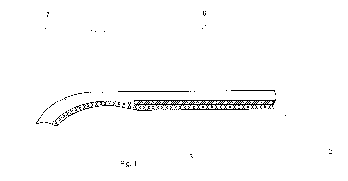
Figure I: lateral section through a portion of a pressure vessel
according to the invention
Figure 2: lateral section through a portion of another pressure
vessel according to the invention
Detailed description of embodiments
Figure 1 shows a lateral section through a portion of a pressure
vessel according to the invention. In particular, the Figure shows
a section through the wall of a pressure vessel according to the
invention. On its exterior, the pressure vessel wall has a winding
1 consisting of a fibre composite material. The winding 1 is applied
on a pressure vessel blank, comprising a cylindrical pipe 2 and a
liner as the inner layer. The cylindrical pipe 2 is located in the
area of the cylindrical central portion 6 of the pressure vessel.
The liner 3 has an outer geometry for receiving the cylindrical pipe
2 so that the cylindrical pipe 2 positively engages with the liner
3. This positive engagement is located at the transition from the
cylindrical central portion 6 of the pressure vessel to the pole cap
region 7. The
outer geometry of the liner 3 has a recess the
cylindrical pipe 2 rests against. The positive engagement can be
such as to act in the axial and/or in the radial direction.
Figure 2 shows a lateral section through a portion of a different
pressure vessel according to the invention. The pressure vessel has
a pole cap reinforcement 4 in the pole cap region 7 which is applied
on the pole cap region 7 before the winding is applied on the pressure
vessel blank.
Like the pressure vessel blank, the pole cap
reinforcement 4 can also be manufactured separately, facilitating
production of the pole cap reinforcement 4 and allowing production
of the pole cap reinforcement 4 such that an optimum reinforcing
effect is achieved. A connection piece 5, also called boss, is
inserted in the pole cap reinforcement 4 and the winding 1, which
connection piece is used for filling the pressure vessel and for
Date Recue/Date Received 2022-01-31
CA 03149338 2022-01-31
13
removing the content, for instance a gas. The boss 5 is inserted
in the pressure vessel in such a way that the liner wraps around it.
In the embodiment shown in Fig. 2, the liner 2 has no special outer
geometry for receiving the cylindrical pipe 2, but is a standard
liner with cylindrical outer geometry without any undercuts.
The embodiments shown here are only examples of the present invention
and are therefore not to be understood as limiting. Alternative
embodiments considered by the person skilled in the art are equally
comprised by the scope of protection of the invention.
Date Recue/Date Received 2022-01-31
CA 03149338 2022-01-31
14
List of reference numbers
1 winding
2 cylindrical pipe
3 liner type 4
4 pole cap reinforcement
boss
6 cylindrical central portion
7 pole cap region
Date Recue/Date Received 2022-01-31