Note: Descriptions are shown in the official language in which they were submitted.
5
Furnace and method for operating a furnace
The invention relates to a method for operating a furnace, in particu-
lar an anode furnace, to a control device for a furnace, and to a
furnace, the furnace being formed by a plurality of heating channels
and furnace chambers, the furnace chambers serving to receive
carbonaceous bodies, in particular anodes, and the heating channels
serving to control the temperature of the furnace chambers, the
furnace comprising at least one furnace unit, the furnace unit com-
prising a heating zone, a fire zone and a cooling zone, which for their
part are formed by at least one section comprising furnace chambers,
a suction ramp of the furnace unit being disposed in a section of the
heating zone, and a burner ramp of the furnace unit being disposed in
a section of the fire zone, process air in the heating channels of the
fire zone being heated by means of the burner ramp, and exhaust gas
being suctioned from the heating channels of the heating zone by
means of the suction ramp, an operation of the ramps being con-
trolled by means of a control device of the furnace unit.
CA 03149393 2022-2-24
2
The present method and the device are used in producing anodes
which are needed for fused-salt electrolysis for producing primary
aluminum, for example. These anodes or carbonaceous bodies are
produced as what is referred to as green anodes or raw anodes from
5 petroleum coke, to which pitch is added as a binder, in a molding
process, said green anodes or raw anodes being sintered in an anode
furnace or furnace after molding. This sintering process takes place
in a heat treatment process which runs in a defined manner and in
which the anodes undergo three phases, namely a heating phase, a
10 sintering phase and a cooling phase. In said process, the raw anodes
are located in a heating zone of a "fire" formed in a furnace composed
of the heating zone, a fire zone and a cooling zone and are pre-heated
by the exhaust heat of previously sintered carbonaceous bodies
stemming from the fire zone before the pre-heated anodes are heated
15 to the sintering temperature of about 1200 C in the fire zone. Ac-
cording to the state of the art as known from WO 2013/044968 Al,
for example, the different zones mentioned are defined by an alter-
nately continuing arrangement of different units above furnace
chambers or heating channels which receive the anodes.
20 The fire zone, which is disposed between the heating zone and the
cooling zone, is defined by the fact that a burner mechanism or one
or multiple so-called burner ramps is/are positioned above selected
furnace chambers or heating channels. Anodes burned, i.e., heated to
sintering temperature, immediately prior are located in the cooling
25 zone. A fan or what is referred to as a cooling ramp, by means of
which air is blown into the heating channels of the cooling zone, is
disposed above the cooling zone. Through the heating channels, a
suction mechanism or what is referred to as a suction ramp disposed
above the heating zone transports the air from the cooling zone
30 through the fire zone into the heating zone and, as waste gas or
exhaust gas, from there through a waste gas cleaning system and
CA 03149393 2022-2-24
3
discharges it to the environment. The suction ramp and the burner
ramp form a furnace unit together with the cooling ramp and the
heating channels.
The units mentioned are shifted along the heating channels in the
5 direction of the raw anodes disposed in the furnace at regular time
intervals. For instance, one furnace can comprise multiple furnace
units whose units are shifted one after the other above the furnace
chambers or the heating channels for subsequent heat treatment of
the raw anodes or anodes. Anode furnaces of this kind, which can be
10 configured as open or closed annular kilns in various architectures,
present the problem that a volumetric flow rate of the process air or
the exhaust gases transported through the furnace cannot be meas-
ured directly and only with much effort. For example, it should be
ensured that a sufficient amount of oxygen for burning a fuel of the
15 burner mechanism is available in the heating channels of the furnace.
Since the constructive design of the heating channels prevents direct
measuring of the volumetric flow rate, the volumetric flow rate is
determined indirectly by evaluating pressure and temperature meas-
urements at the heating channels and control signals of a process
20 controller. Alternatively, there have been attempts to determine the
volumetric flow rate by indirect measurement, such as a pressure
measurement in the heating channel and its ratio to a suction capaci-
ty of the suction ramp, as described in more detail in WO
2013/044968 Al. Even in the event of a more precise determination
25 of the volumetric flow rate, however, proper functioning of the
furnace according to a desired or ideal burning curve cannot be
ensured when a heating channel cover is opened or improperly
closed or a heating channel is clogged or blocked, for example.
Hence, in practice, volumetric flow rate assessment is performed by
30 trained furnace personnel in the course of a tour of the furnace
CA 03149393 2022-2-24
4
and/or by assessing status information of a process controller at
regular time intervals. If a malfunction of the furnace caused, for
example, by a discrepancy between the volumetric flow rate and the
fuel is detected, this malfunction is remedied manually by the fur-
5 nace personnel or the ratio of the volumetric flow rate or the process
air and the fuel is adjusted accordingly. Since a tour of the furnace is
carried out at time intervals of up to four hours, for example, dan-
gerous operating states of the furnace which can lead to deflagra-
tions, fires or explosions might not be recognized in time.
10 Hence, the object of the present invention is to propose a method for
operating a furnace and a control device for a furnace by means of
which an operation of the furnace can be improved.
This object is attained by a method having the features of claim 1, a
control device having the features of claim 20, and a furnace having
15 the features of claim 21.
In the method according to the invention for operating a furnace, in
particular an anode furnace, the furnace is formed by a plurality of
heating channels and furnace chambers, the furnace chambers serv-
ing to receive carbonaceous bodies, in particular anodes, and the
20 heating channels serving to control the temperature of the furnace
chambers, the furnace comprising at least one furnace unit, the
furnace unit comprising a heating zone, a fire zone and a cooling
zone, which for their part are formed by at least one section compris-
ing furnace chambers, a suction ramp of the furnace unit being
25 disposed in a section of the heating zone, and a burner ramp of the
furnace unit being disposed in a section of the fire zone, combustion
air or process air in the heating channels of the fire zone being
heated by means of the burner ramp, and hot air or exhaust gas being
suctioned from the heating channels of the heating zone by means of
30 the suction ramp, an operation of the ramps being controlled by
CA 03149393 2022-2-24
5
means of a control device of the furnace unit, wherein an amount of
fuel of the burner ramp is determined by means of the control device,
a ratio of the combustion air or process air and the amount of fuel
being determined for at least one section by means of the control
5 device.
Fuel, such as gas or oil, is typically burned by means of the burner
ramp or burners of the burner ramp, preferably multiple burner
ramps. An amount of fuel consumed, i.e., burned, by the burner ramp
during a time interval is determined by means of the control device
10 with respect to said time interval. The amount of fuel consumed by
the burner ramp, i.e., a primary amount of fuel, can be determined by
measuring using a quantity measuring device or the like, for example.
Furthermore, an amount of von process air in at least one section,
preferably in multiple or all sections, of the heating zone and the fire
15 zone can be determined by means of the control device. This deter-
mination can be determined in various ways, such as by measuring
pressures or positions of throttle valves relative to a time interval.
According to the invention, a ratio of the process air and the amount
of fuel is determined for at least one section by means of the control
20 device, preferably within the same time interval. By determining the
ratio, which can be easily calculated arithmetically or mathematically
by means of a computer program product of the control device, for
example, it becomes possible to find out whether the ratio corre-
sponds to a presumed operating state of the furnace or a burning
25 curve or deviates therefrom. In the event of a deviation, an excess or
a lack of fuel or process air can lead to critical operating states of the
furnace. This deviation can be signaled by the control device, for
example, in order to inform the furnace personnel so that the furnace
personnel can locate the issue or manually adjust the ratio outside of
30 rotational furnace tours. Alternatively, the control device can also
automatically adjust the presumed ratio or control the determined
CA 03149393 2022-2-24
6
ratio of the process air and the amount of fuel according to the
presumed ratio. If no safe operating state can be established, the
furnace can be brought into a safe operating state by shutting off the
primary fuel supply. Overall, an improved operation of the furnace
5 can be ensured in this way while avoiding dangerous operating
states. In particular, high emissions and high fuel consumption can be
avoided as well.
A ratio of the process air and the amount of fuel can be calculated for
all sections of the heating zone and/or the fire zone, preferably for
10 all sections of the furnace, by means of the control device. Thus, an
essentially complete monitoring of the respective zones or the entire
furnace with regard to undesired operating states can be ensured.
Furthermore, it also becomes possible to adjust the ratio of the
process air and the amount of fuel in the different sections in a more
is targeted manner, in particular since the sections are connected to
each other in series, which means that a ratio of the process air and
the amount of fuel affects an operating state of the furnace in a flow
direction across subsequent sections.
A primary amount of fuel of the burner ramp can be determined by
20 means of the control device, wherein a secondary amount of fuel of
the heating zone and/or the burner zone can be determined as a
function of at least one chemical property of the anodes or carbona-
ceous bodies by means of the control device. The primary amount of
fuel can be an amount of gas, natural gas, oil or the like which is
25 consumed by the burner ramp or the burner ramps during a time
interval, for example. The secondary amount of fuel can be an amount
of pitch contained in the carbonaceous bodies or raw anodes, for
example. Pitch is typically used as a binder in a molding process of
raw anodes. The pitch or pitch distillates can be released at a tem-
30 perature between 200 C and 600 C. Depending on the chemical
composition of the carbonaceous body or the anode, it contains a
CA 03149393 2022-2-24
7
greater or smaller amount of pitch, which is known in principle.
Depending on the temperature of the individual anode or its heating
behavior, a greater or smaller amount of pitch distillate can be
released, which burns in the fire zone. This secondary amount of fuel
5 in the form of pitch distillate or other substances contained in the
raw anodes and usable as fuel results in a change in a ratio of the
amount of fuel and the process air. Hence, it is advantageous for the
control device to be able to determine the secondary amount of fuel.
According to a particularly simple embodiment, this determination
10 can take place based on an amount of pitch present in the raw an-
odes, for example. A continuous determination of the secondary
amount of fuel can take place by determining the heating of the
carbonaceous products and a release of combustible components
depending thereon based on a thermodynamic mathematical model,
15 for example.
The primary amount of fuel can be calculated by means of the control
device as a function of a temperature measured in the heating chan-
nel of the fire zone. Thus, it is no longer necessary to determine an
amount of fuel by means of quantity measuring devices, which are
20 consequently unnecessary as well. In principle, it remains possible to
determine the primary amount of fuel by direct recordal of pulse
times for an oil or gas injection of individual burners. Since a tem-
perature in the heating channel of the fire zone is measured anyway
for operating a burner ramp, this temperature can be advantageously
25 used by the control device for calculating the primary amount of fuel.
This calculation can be performed using empirical values for fuel
consumptions at certain temperatures measured in the fire zone, for
example. For instance, the calculation can be performed based on a
mathematical function of the primary amount of fuel and the temper-
30 ature.
CA 03149393 2022-2-24
8
The secondary amount of fuel of the heating zone can be calculated or
estimated as a function of a mass loss, a degree of coking and/or a
temperature of the anodes or carbonaceous bodies. Consequently, the
secondary amount of fuel can be calculated by the control device by
5 means of a mathematical model. A heat content or a temperature of
the carbonaceous bodies has an impact on the release of pitch distil-
lates, for example, which means that a proportion of the primary
amount of fuel released by the carbonaceous bodies during a time
interval can be calculated by means of the control device when a
10 chemical property of the carbonaceous bodies, such as a mass frac-
tion of pitch, a dwell time of the carbonaceous bodies in the furnace,
a temperature level of the carbonaceous bodies during this time
interval, therefore a degree of coking and therefore also a mass loss
are known. A temperature of carbonaceous bodies in different sec-
15 can be measured directly. Direct measuring of a temperature
can also be performed on individual carbonaceous bodies as a refer-
ence measurement. The control device can store and recalculate
these measured values for a carbonaceous body or anode depending
on the position of the carbonaceous body in a section or zone so that
20 the control device can continuously adjust a degree of coking for the
carbonaceous body at hand and therefore a secondary amount of fuel
represented by the carbonaceous body.
The control device can calculate the temperature of the carbonaceous
bodies. In addition to directly measuring the temperature of the
25 anodes or carbonaceous bodies by means of sensors or other meas-
urement devices, the control device can also calculate the tempera-
ture of the carbonaceous bodies by means of a mathematical model.
This calculation can take the temperatures in the heating channels of
the furnace measured by the control device into account. Further-
30 more, the respective temperatures at the suction ramp, at the burner
ramp and in heating channels of other sections can be measured. The
CA 03149393 2022-2-24
9
control device can calculate the temperature of the respective carbo-
naceous bodies from these temperatures of the furnace, which are
essentially measured simultaneously. This calculation can take other
operating parameters of the furnace into account. The calculation can
5 also be performed based on empirical values, which are represented
by mathematical functions, for example. In this case, direct measur-
ing of the temperature of the carbonaceous bodies is no longer
required during regular operation of the furnace.
The control device can calculate a total amount of fuel from the
10 primary amount of fuel and the secondary amount of fuel. In particu-
lar, this makes it possible for the amount of fuel burned in the area of
the burner ramp and composed of the primary amount of fuel and the
secondary amount of fuel to be determined even more precisely. In
this way, the amounts of fuel supplied to the heating channels in the
15 heating zone and in the fire zone can be determined more precisely,
wherein the required ratios of these amounts of fuel to residual
oxygen contained in the exhaust gas can be determined for optimal
combustion. Consequently, a ratio of the process air and the amount
of fuel can also be determined more precisely.
20 A volumetric flow rate of the sections between the suction ramp and
the cooling ramp can be determined by means of the control device
based on a pressure measured in the heating channel or other physi-
cal parameters in the heating channel. This volumetric flow rate can
be calculated by the control device by means of a mathematical
25 model. For example, a pressure in the heating channel can be meas-
ured in each section and at the exit of the fire zone.
The volumetric flow rate in the heating channel can be determined by
means of the control device from a ratio of the suction capacity and
the pressure in the suction ramp and a ratio of the suction capacity
30 and the pressure in the heating channel. The respective ratios can
CA 03149393 2022-2-24
10
each be formed separately and the volumetric flow rate can be de-
rived therefrom.
Respective pressures in a plurality of heating channels can be corre-
lated with the pressure in the suction ramp. A volumetric flow rate
5 can also be determined individually for individual heating channels if
the pressure in the individual section is known, the pressure in the
sections being correlated with the pressure in the suction ramp.
Since a pressure deviation in a heating channel affects the pressures
in the other heating channels or sections, a changed volumetric flow
10 rate can be determined or calculated with a relative correlation to
the pressure measured in the suction ramp.
The suction capacity of the suction ramp can be determined by means
of the control device by determining a valve position of a throttle
valve of the suction ramp. A cross section of a suction channel can be
15 varied by adjusting the throttle valve with the result that the suction
capacity of the suction ramp depends inter alia on the adjusted cross
section of the suction channel. If a throttle valve or a similar feature
of this kind is used, a suction capacity can therefore be deduced from
a valve position, which is indicated in angular degrees relative to the
20 suction channel, for example. A valve position can be determined in a
particularly simple and precise manner by means of a rotary potenti-
ometer or a rotary encoder, for example.
It is particularly advantageous for the volumetric flow rate in the
heating channel of the heating zone and/or the fire zone to be deter-
25 mined. Since differences in the volumetric flow rate due to the burn-
ing method may arise in this context, they can be taken into account
in this manner. For instance, volumetric flow rates in the heating
channels of the zones mentioned above can each be determined
separately. Thus, a differentiated view of the operating state in the
30 respective zones of the furnace becomes possible. Also, the volumet-
CA 03149393 2022-2-24
11
ric flow rate can be determined even more precisely if a change in
density of air in the heating channel is calculated from a temperature
gradient across the respective sections or heating channels and the
temperature, and this change in density is taken into account when
5 determining the volumetric flow rate. Hence, a calculation of the
volumetric flow rate can be corrected by a correction factor which
can be derived from a calculation of the change in density based on
the temperature gradient and the temperature.
Furthermore, an enthalpy flow rate of the sections can be determined
10 by means of the control device. The enthalpy flow rate can also be
calculated by the control device by means of a mathematical model.
The enthalpy flow rate can be easily calculated through a ratio of
respective pressures and respective volumetric flow rates in a plural-
ity of heating channels.
15 A consistency of the volumetric flow rate and the enthalpy flow rate
can be calculated by means of the control device, wherein potential
amounts of false air of the heating channels can be determined based
on said calculation. If the volumetric flow rate and the enthalpy flow
rate deviate from a presumed ratio, this can point to a possible
20 malfunction. In this context, respective amounts of false air for the
respective heating channels may be determined based on the com-
parative calculation of the volumetric flow rate and the enthalpy flow
rate by means of the control device. The amount of false air can be a
result of improperly closed heating channel covers or at least partial-
25 ly blocked heating channels, for example. The amount of false air can
be calculated by the control device by means of a mathematical
model. The amount of false air can be calculated iteratively, for
example, based on empirical values represented by mathematical
functions.
CA 03149393 2022-2-24
12
Furthermore, an amount of air introduced into the heating channels
and potential amounts of false air can be determined by means of the
control device. The amount of air introduced into the heating chan-
nels can be determined at a fan ramp in the area of the cooling zone,
5 for example. The amount of air at the fan ramp can be determined by
determining a valve position of a throttle valve. A cross section of a
suction channel can be varied by adjusting the throttle valve with the
result that the amount of air introduced depends inter alia on the
adjusted cross section of the suction channel. If a throttle valve or a
10 similar feature of this kind is used, a suction capacity or an amount
of air can therefore be deduced from a valve position, which is indi-
cated in angular degrees relative to the suction channel, for example.
The amount of air can be used by the control device to calculate the
volumetric flow rate. Alternatively, an introduced amount of air can
15 be determined by measuring the pressure in the heating channels
between the fan ramp and the burner ramp. Furthermore, it is possi-
ble for an introduced amount of air to be determined via a speed of
ventilators.
A total volumetric flow rate can be determined by means of the
20 control device from the volumetric flow rate, a volumetric fuel flow
rate and the amount of false air. In this case, the total volumetric
flow rate or the introduced amount of air, the amount of false air and
a volume of the amount of fuel represent the process air made avail-
able during a time interval, in particular oxygen for the amount of
25 fuel used during said time interval. The volumetric fuel flow rate
results from the volume of the used amount of fuel in the process air.
If a primary amount of fuel and a secondary amount of fuel are
known, a primary volumetric fuel flow rate and a secondary volumet-
ric fuel flow rate can be taken into account when determining the
30 total volumetric flow rate. The ratio of the process air and the
CA 03149393 2022-2-24
13
amount of fuel can be determined even more precisely in this man-
ner.
The control device can correct the volumetric flow rate and/or the
enthalpy flow rate. This correction of the calculated volumetric flow
5 rate or the enthalpy flow rate can take place taking other operating
parameters, such as an amount of false air or other measured data,
into account.
The volumetric flow rate, preferably of the sections and/or the
suction ramp and/or the cooling ramp, and/or an introduced amount
10 of air can be adjusted in such a manner by means of the control
device that a target ratio of the process air and the primary amount
of fuel and/or the secondary amount of fuel, preferably of the total
amount of fuel, can be reached, the target ratio being defined in the
control device. The control device can calculate a current ratio of the
15 process air and the amount of fuel and control it according to the
target ratio by adjusting the introduced amount of air. To this end,
the control device can have one or multiple controllers, such as PID
controllers. Thus, it is possible to ensure at all times that a ratio of
the process air and the amount of fuel does not deviate to a point at
20 which dangerous operating states arise. Also, a state which is optimal
for a combustion of the different fuels can be established.
This adjustment can take place by a control of the volumetric flow
rate at the suction ramp and/or the cooling ramp by means of the
control device. This control of the volumetric flow rate can be ac-
25 complished by actuating throttle valves at the suction ramp and/or
the cooling ramp. The control can act on a motor drive of the throttle
valve or throttle valves with the result that the volumetric flow rate
is influenced.
CA 03149393 2022-2-24
14
Furthermore, the primary amount of fuel introduced can be adjusted
in such a manner by means of the control device that a target ratio of
the process air and the total amount of fuel can be reached, the target
ratio being defined in the control device. Consequently, controlling a
5 current ratio of the process air and the total amount of fuel by meter-
ing the amount of fuel at the burner ramp is possible as well. The
primary amount of fuel can be controlled in connection with a control
of the volumetric flow rate, in which case the control device can also
establish a cascade control.
10 The control device according to the invention is configured to oper-
ate a furnace, in particular an anode furnace, the furnace being
formed by a plurality of heating channels and furnace chambers, the
furnace chambers serving to receive carbonaceous bodies, in particu-
lar anodes, and the heating channels serving to control the tempera-
15 ture of the furnace chambers, the furnace comprising at least one
furnace unit, the furnace unit comprising a heating zone, a fire zone
and a cooling zone, which for their part are formed by at least one
section comprising furnace chambers, a suction ramp of the furnace
unit being disposed in a section of the heating zone, and a burner
20 ramp of the furnace unit being disposed in a section of the fire zone,
the burner ramp being configured to heat process air in the heating
channels of the fire zone, and the suction ramp being configured to
suction exhaust gas from the heating channels of the heating zone,
the control device of the furnace unit being configured to control an
25 operation of the ramps, wherein the control device is configured to
determine an amount of fuel of the burner ramp, the control device
being configured to determine a ratio of the process air and the
amount of fuel for at least one section. Reference is made to the
description of advantages of the method according to the invention
30 regarding the advantages of the control device according to the
invention. Further advantageous embodiments of a control device are
CA 03149393 2022-2-24
15
apparent from the description of features of the dependent claims
referring to method claim 1.
The furnace, in particular the anode furnace, according to the inven-
tion comprises a control device according to the invention. Further
5 embodiments of a furnace are apparent from the description of
features of the depending claims referring to method claim 1.
Hereinafter, a preferred embodiment of the invention is explained in
more detail with reference to the accompanying drawings.
Fig. 1 is a schematic illustration of a
furnace in a perspective
10 view;
Fig. 2 is a schematic illustration of a
furnace unit of the furnace
in a longitudinal section view;
Fig. 3 shows a temperature distribution in
the furnace unit;
Fig. 4 is an illustration of the furnace
unit of Fig. 2 with a
15 process diagram for an embodiment of the method for
operating a furnace.
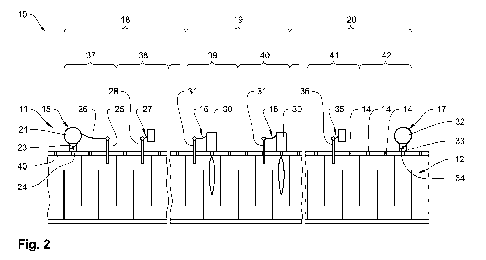
A combined view of Figs. 1 and 2 shows a schematic illustration of an
anode furnace or furnace 10 comprising a furnace unit 11. Furnace 10
has a plurality of heating channels 12, which extend parallel to each
20 other along interposed furnace chambers 13. Furnace chambers 13
serve to accommodate anodes or carbonaceous bodies (not shown).
Heating channels 12 extend in a meandering shape in the longitudinal
direction of furnace 10 and have heating channel openings 14 at
regular intervals, which are each covered by a heating channel cover
25 (not shown).
Furnace unit 11 further comprises a suction ramp 15, one or multiple
burner ramps 16 and a cooling ramp 17. Their positions on fur-
CA 03149393 2022-2-24
16
nace 10 functionally define a heating zone 18, a fire zone 19 and a
cooling zone 20, respectively. In the course of the production process
of the anodes or carbonaceous bodies, furnace unit 11 is displaced in
the longitudinal direction of furnace 10 relative to furnace cham-
5 hers 13 or carbonaceous bodies by shifting suction ramp 15, burner
ramps 16 and cooling ramp 17 with the result that all anodes or
carbonaceous bodies located in anode furnace 10 pass through
zones 18 to 20.
Suction ramp 15 is essentially formed by a collecting channel 21,
which is connected to an exhaust gas cleaning system (not shown) via
an annular channel 22. Collecting channel 21 for its part is connected
to a heating channel opening 14 via a connecting channel 23 in each
case, a throttle valve 24 being disposed on connecting channel 23 in
the case at hand. Furthermore, a measuring element (not shown) for
15 pressure measuring is disposed within collecting channel 21, and
another measuring element 25 for temperature measuring is dis-
posed in each heating channel 12 directly upstream of collecting
channel 21 and is connected thereto via a data line 26. Moreover, a
measuring ramp 27 comprising measuring elements 28 for each
20 heating channel 12 is disposed in heating zone 18. A pressure and a
temperature in the respective portion of heating channel 12 can be
determined by means of measuring ramp 27.
Three burner ramps 16 comprising burners 30 and measuring ele-
ments 31 for each heating channel 12 are placed in fire zone 19.
25 Burners 30 each burn a flammable fuel in heating channel 12, a
burner temperature being measured by means of measuring ele-
ment 31. This makes it possible for a desired burner temperature to
be set in the area of fire zone 19.
Cooling zone 20 comprises cooling ramp 17, which is formed by a
30 feeding channel 32 comprising respective connecting channels 33 and
CA 03149393 2022-2-24
17
throttle valves 34 for being connected to heating channels 12. Fresh
air is blown into heating channels 12 via feeding channel 32. The
fresh air cools heating channels 12 or the anodes or carbonaceous
bodies located in furnace chambers 13 in the area of cooling zone 20,
5 the fresh air continuously heating up until it reaches fire zone 19. In
this context, Fig. 3 shows a diagram of the temperature distribution
relative to the length of heating channel 12 and zones 18 to 20.
Furthermore, a measuring ramp 35 or what is referred to as a zero
pressure ramp comprising measuring elements 36 is disposed in
10 cooling zone 20. Measuring elements 36 serve to detect a pressure in
respective heating channels 12. The pressure in heating channel 12 is
essentially 0 in the area of measuring elements 36, a high pressure
forming between measuring elements 36 and cooling ramp 17, and a
low pressure forming in heating channels 12 between measuring
15 elements 36 and suction ramp 15. Consequently, the fresh air flows
from cooling ramp 17 through heating channels 12 toward suction
ramp 15. Ramps 15 to 17 are each disposed in sections 37 to 42,
sections 37 to 42 for their part each being formed by heating channel
portions 12. Sections adjacent to sections 37 to 42 are not shown for
20 the sake of clarity of the figure.
Fig. 4 shows furnace unit 11, which has been illustrated in Fig. 2, in
connection with a process flow for operating furnace 10, the process
flow being illustrated as an example. In particular, an operation of
suction ramp 15, burner ramp 16 and cooling ramp 17 is controlled
25 by means of a control device (not shown) of furnace unit 11, the
control device comprising at least one means for data processing,
such as a programmable logic controller or a computer, which is used
to execute a computer program product or at least one software. A
ratio of the process air and the amount of fuel is determined for at
30 least one of sections 37 to 42 by means of the control device.
CA 03149393 2022-2-24
18
A primary amount of fuel of burner ramps 16 is determined by means
of the control device in a method step 43. Furthermore, a tempera-
ture of the anodes or carbonaceous bodies (not shown) is calculated
by means of the control device in a method step 44. This can also
take place by measuring a temperature via measuring ramp 27
and/or measuring ramp 35. Furthermore, a secondary amount of fuel
of heating zone 18 is calculated by means of the control device as a
function of at least one chemical property of the anodes or carbona-
ceous bodies, in particular a temperature, in a method step 45. In a
method step 46, the control device calculates a total amount of fuel
from the primary amount of fuel and the secondary amount of fuel.
Furthermore, the control device calculates a volumetric flow rate in
sections 37 to 42 or suction ramp 15 based on a pressure measured
in heating channel 12 in a method step 47. The volumetric flow rate
can be determined by the control device based on a ratio of the
suction capacity and the pressure in suction ramp 15 and a ratio of
the suction capacity and the pressure in heating channel 12, for
example. Furthermore, an enthalpy flow rate in sections 37 to 42 is
calculated in method step 47. In a method step 48, the control device
determines a consistency of the volumetric flow rate and the enthal-
py flow rate, potential amounts of false air in the heating channels 12
being determined by the control device based on a calculation. The
control device uses potential amounts of false air to correct the
volumetric flow rate in method step 47.
In method step 49, the control device calculates a ratio of an amount
of air introduced or process air and the total amount of fuel from the
volumetric flow rate from method step 47 and the total amount of
fuel from method step 46. Furthermore, a target ratio of the process
air and the total amount of fuel is defined in the control device,
which means that a comparison of the ratios is drawn in method
step 49. The control device now controls the volumetric flow rate at
CA 03149393 2022-2-24
19
suction ramp 15 based on the comparison by adjusting throttle
valve 24 by means of an actor 50 in such a manner that the desired
target ratio of the process air and the amount of fuel is established.
The primary amount of fuel introduced can also be controlled
through the control device in order to control the ratio. Overall, this
can ensure at all times that the ratio of the process air and the
amount of fuel does not cause dangerous operating states; moreover,
the operation of furnace 10 can be optimized.
CA 03149393 2022-2-24