Note: Descriptions are shown in the official language in which they were submitted.
NOSE-WHEEL STEERING SYSTEM
FIELD
[0001] The present disclosure relates generally to aircraft steering
systems and,
more particularly, to aircraft nose-wheel steering systems.
BACKGROUND
[0002] Aircraft typically employ nose-wheel steering systems to steer
the aircraft
while taxiing on the ground. A typical nose-wheel steering system includes a
collar gear
provided upon a strut associated with the nose-wheel. Various actuators and
gear trains
may be associated with rotating the collar gear, and hence the strut, thereby
adjusting the
orientation of the nose-wheel to affect steering (i.e., the direction of the
taxiing aircraft).
Current actuator and gear train arrangements typically include a rack and
pinion type
mechanism that converts linear movement of a rack into to rotary movement.
These
arrangements are relatively large and, therefore, add weight and space claim
to the
landing gear and are not always easy to accommodate with other landing gear
components. Further, these larger actuator and gear train arrangements may not
be
aesthetically pleasing.
SUMMARY
[0003] A nose-wheel steering system is disclosed herein. In accordance
with
various embodiments, the nose-wheel steering system may comprise an actuator
including a drive shaft configured to rotate about a first axis. A bevel gear
may be
rotationally coupled to the drive shaft of the actuator. The bevel gear may be
configured
to rotate about the first axis. A collar gear may be intermeshed with the
bevel gear. The
collar gear may be configured to rotate about a second axis, generally
perpendicular to
the first axis.
[0004] In various embodiments, the actuator may include a single vane
hydraulic
rotary actuator. In various embodiments, the actuator may include a rotating
vane and a
stationary vane. The rotating vane may be rotationally coupled to the drive
shaft.
[0005] In various embodiments, a first conduit may be fluidly coupled
to a first
hydraulic chamber of the actuator. A second conduit may be fluidly coupled to
a second
1
Date recue/ date received 2022-02-17
hydraulic chamber of the actuator. A control valve assembly may be coupled to
the first
conduit and the second conduit. The control valve assembly may be configured
to control
fluid flow to each of the first hydraulic chamber and the second hydraulic
chamber.
[0006] In various embodiments, a steering controller may be operably
coupled to
the control valve assembly. The steering controller may be configured to
control
actuation of the control valve assembly.
[0007] In various embodiments, a gear train may be rotationally coupled
between
the drive shaft of the actuator and the bevel gear. In various embodiments,
the gear train
may include a planetary gear system.
[0008] In various embodiments, the drive shaft may form a sun gear of
the
planetary gear system.
[0009] A shock strut assembly for an aircraft landing gear assembly is
also
disclosed herein. In accordance with various embodiments, shock strut assembly
may
comprise a strut cylinder, a strut piston configured to telescope relative to
the strut
cylinder, and a steering system coupled to the strut piston and configured to
rotate the
strut piston about a piston axis of rotation. The steering system may comprise
an actuator
including a drive shaft configured to rotate about a second axis, a bevel gear
rotationally
coupled to the drive shaft of the actuator and configured to rotate about the
second axis,
and a collar gear intermeshed with the bevel gear and configured to rotate
about the
piston axis of rotation. The second axis may be non-parallel to the piston
axis of rotation.
[0010] In various embodiments, the steering system may further comprise
a gear
train rotationally coupled between the drive shaft of the actuator and the
bevel gear. In
various embodiments, the gear train includes a planetary gear system. The
planetary gear
system may comprise a non-rotating ring gear, a planet gear configured to
rotate about an
inner circumferential surface of the non-rotating ring gear, and a carrier
coupled to the
planet gear and configured to rotate the bevel gear. Rotation of the planet
gear may be
driven by rotation of the drive shaft about the second axis.
[0011] In various embodiments, an outer circumferential surface of the
carrier
may define a toothed surface of the bevel gear. The toothed surface of the
bevel gear may
be intermeshed with the collar gear.
2
Date recue/ date received 2022-02-17
[0012] In various embodiments, the actuator may include a rotating vane
and a
stationary vane. The rotating vane may be rotationally coupled to the drive
shaft.
[0013] In various embodiments, the steering system may further comprise
a first
conduit fluidly coupled to a first hydraulic chamber of the actuator, a second
conduit
fluidly coupled to a second hydraulic chamber of the actuator; and a control
valve
assembly coupled to the first conduit and the second conduit. The control
valve assembly
may be configured to control fluid flow to each of the first hydraulic chamber
and the
second hydraulic chamber. In various embodiments, the second axis may be
generally
perpendicular to the piston axis of rotation.
[0014] A nose landing gear assembly is also disclosed herein. In
accordance with
various embodiments, the nose landing gear assembly may comprise a shock strut
assembly and a nose-wheel steering system coupled to the shock strut assembly.
The
shock strut assembly may include a strut cylinder and a strut piston
configured to
telescope relative to the strut cylinder. The nose-wheel steering assembly may
be
configured to rotate the strut piston about a piston axis of rotation. The
nose-wheel
steering system may comprise: an actuator including a drive shaft configured
to rotate
about a second axis, a bevel gear rotationally coupled to the drive shaft of
the actuator
and configured to rotate about the second axis, and a collar gear intermeshed
with the
bevel gear and configured to rotate about the piston axis of rotation. The
second axis may
be non-parallel to the piston axis of rotation.
[0015] In various embodiments, a nose wheel assembly may be coupled to
the
strut piston. An axis of rotation of the nose wheel assembly may be generally
perpendicular to the piston axis of rotation.
[0016] In various embodiments, the actuator may include a rotating vane
and a
stationary vane. The rotating vane may be rotationally coupled to the drive
shaft.
[0017] In various embodiments, a planetary gear system may be
rotationally
coupled between the drive shaft and the bevel gear. In various embodiments,
the actuator
may comprise a single vane hydraulic rotary actuator. The second axis may be
generally
perpendicular to the piston axis of rotation.
[0018] The foregoing features and elements may be combined in any
combination, without exclusivity, unless expressly indicated herein otherwise.
These
3
Date recue/ date received 2022-02-17
features and elements as well as the operation of the disclosed embodiments
will become
more apparent in light of the following description and accompanying drawings.
BRIEF DESCRIPTION OF THE DRAWINGS
[0019] The accompanying drawings illustrate various embodiments
employing
the principles described herein and are a part of the specification. The
illustrated
embodiments are meant for description and not to limit the scope of the
claims.
[0020] FIG. 1 illustrates an aircraft having left, right and nose
landing gear
assemblies and wheels mounted thereon, in accordance with various embodiments;
[0021] FIG. 2 illustrates a nose landing gear assembly, in accordance
with various
embodiments;
[0022] FIG. 3A and illustrates a nose-wheel steering system, in
accordance with
various embodiments;
[0023] FIG. 3B illustrates a cross-section view of a nose-wheel
steering system
taken along the line 3B-3B in FIG. 3A, in accordance with various embodiments;
[0024] FIGs. 4A, 4B, and 4C illustrate a single vane hydraulic rotary
actuator for
a nose-wheel steering system, in accordance with various embodiments;
[0025] FIG. 5 illustrates a cross-section view of a nose-wheel steering
system
having a planetary gear system operably coupled between a hydraulic rotary
actuator and
a bevel gear, in accordance with various embodiments; and
[0026] FIG. 6 illustrates a dual vane hydraulic rotary actuator of a
nose-wheel
steering system, in accordance with various embodiments.
DETAILED DESCRIPTION
[0027] The following detailed description of various embodiments herein
makes
reference to the accompanying drawings, which show various embodiments by way
of
illustration. While these various embodiments are described in sufficient
detail to enable
those skilled in the art to practice the disclosure, it should be understood
that other
embodiments may be realized and that changes may be made without departing
from the
scope of the disclosure. Thus, the detailed description herein is presented
for purposes of
illustration only and not of limitation. Furthermore, any reference to
singular includes
plural embodiments, and any reference to more than one component or step may
include
a singular embodiment or step. Also, any reference to attached, fixed,
connected, or the
4
Date recue/ date received 2022-02-17
like may include permanent, removable, temporary, partial, full or any other
possible
attachment option. Additionally, any reference to without contact (or similar
phrases)
may also include reduced contact or minimal contact. It should also be
understood that
unless specifically stated otherwise, references to "a," "an," or "the" may
include one or
more than one and that reference to an item in the singular may also include
the item in
the plural. Further, all ranges may include upper and lower values and all
ranges and ratio
limits disclosed herein may be combined.
[0028] With reference to FIG. 1, an aircraft 100 is illustrated. In
accordance with
various embodiments, aircraft 100 may include one or more landing gear
assemblies,
such as, for example, a left landing gear assembly 102 (or port-side landing
gear
assembly), a right landing gear assembly 104 (or starboard-side landing gear
assembly)
and a nose landing gear assembly 106. Each of left landing gear assembly 102,
right
landing gear assembly 104, and nose landing gear assembly 106 may support
aircraft 100
when not flying, allowing aircraft 100 to taxi, takeoff, and land safely and
without
damage to aircraft 100. In various embodiments, left landing gear assembly 102
may
include a left shock strut assembly 108 and a left wheel assembly 110, right
landing gear
assembly 104 may include a right shock strut assembly 112 and a right wheel
assembly
114, and nose landing gear assembly 106 may include a nose shock strut
assembly 116
and a nose wheel assembly 118. One or more pilot steering input(s) 120 (e.g.,
steering
wheels, pedals, knobs, or the like) may be located in a cockpit of aircraft
100.
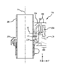
[0029] Referring now to FIG. 2, nose landing gear assembly 106 is
illustrated. In
accordance with various embodiments, shock strut assembly 116 of nose landing
gear
assembly 106 includes a strut cylinder 202 and a strut piston 204. Strut
piston 204 may be
operatively coupled to strut cylinder 202. Strut cylinder 202 may be
configured to receive
strut piston 204 in a manner that allows the two components to telescope with
respect to
one another. Strut piston 204 may translate into and out strut cylinder 202,
thereby
absorbing and damping loads imposed on nose landing gear assembly 106. An axle
206
of nose wheel assembly 118 may be coupled to an end of strut piston 204 that
is opposite
strut cylinder 202. The nose wheels have been removed from nose wheel assembly
118 in
FIG. 2 to more clearly illustrate the features of shock strut assembly 116.
Date recue/ date received 2022-02-17
[0030] In various embodiments, nose landing gear assembly 106 may
include a
torque link 208 coupled to shock strut assembly 116 and/or to axle 206. Torque
link 208
includes a first (or upper) arm 210 and a second (or lower) arm 212. First arm
210 is
pivotably coupled to second arm 212. Strut cylinder 202 is coupled to an
attachment
linkage 214 configured to secure shock strut assembly 116 to the aircraft 100
and to
translate nose landing gear assembly 106 between the landing gear up and
landing gear
down positions. Nose landing gear assembly 106 may include one or more drag
brace(s)
such as drag brace 216. In various embodiments, drag brace 216 may be located
proximate an aft side of shock strut assembly 116. Nose landing gear assembly
106 may
include one or more hydraulic fluid lines (i.e. conduits), such as hydraulic
fluid line 210.
[0031] In accordance with various embodiments, nose landing gear
assembly 106
includes a nose-wheel steering system 220. Nose-wheel steering system 220 is
operably
coupled to nose wheel assembly 118 via shock strut assembly 116. In this
regard, and as
described in further detail below, nose-wheel steering system 220 is
configured to rotate
strut piston 204 about a piston axis of rotation A (also reference to as "axis
A"), thereby
adjusting the orientation of the nose wheel assembly 118 and the taxiing
direction of the
aircraft 100. Axis of rotation A may be parallel to the direction of
translation of strut
piston 204 relative to strut cylinder 202. In various embodiments, axis of
rotation A may
be generally perpendicular to the axis of rotation W of nose wheel assembly
118. As used
in the previous context only, "generally perpendicular" means 100 from
perpendicular.
[0032] Nose-wheel steering system 220 includes a steering collar
housing 222, a
gear assembly housing 224, and an actuator housing 226. In various
embodiments, gear
assembly housing 224 and actuator housing 226 may include a generally
cylindrical
shape. For example, a cross-section of gear assembly housing 224 and actuator
housing
226, taken in a plane parallel to axis of rotation A, may be generally
circular. While gear
assembly housing 224 and actuator housing 226 are illustrated as located on an
aft-side of
steering collar housing 222, the size and/or shape of gear assembly housing
224 and
actuator housing 226, along with the orientation of the rotating components
located in
steering collar housing 222, gear assembly housing 224, and actuator housing
226
(described in further detail below), allow gear assembly housing 224 and
actuator
housing 226 to be located in other locations about axis of rotation A. For
example, gear
6
Date recue/ date received 2022-02-17
assembly housing 224 and actuator housing 226 may be located on the forward-
side, the
port-side, or the starboard-side of steering collar housing 222. In this
regard, a location of
gear assembly housing 224 and actuator housing 226 may be selected based not
only on
available space, but also based on aesthetics.
[0033] Referring now to FIG. 3A and FIG. 3B, a perspective view and a
cross-
section view, respectively, of nose-wheel steering system 220 are illustrated.
The nose-
wheel steering system 220 includes a collar gear 230. Collar rear may be
located in
steering collar housing 222. Collar gear 230 is coupled to strut piston 204
such that
rotation of collar gear 230 about axis of rotation A is transferred to strut
piston 204. In
this regard, rotation of collar gear 230 about axis of rotation A causes
rotation of strut
piston 204 about axis of rotation A.
[0034] Nose-wheel steering system 220 further includes a bevel gear
240. Bevel
gear may be located in gear assembly housing 224. Bevel gear 240 engages (i.e.
is
intermeshed with) collar gear 230. Bevel gear 240 rotates about a bevel gear
axis of
rotation B (also referred to as "axis B"). Axis of rotation B is non-parallel
to axis of
rotation A. In various embodiments, axis of rotation B is generally
perpendicular to axis
of rotation A of collar gear 230. As used in the previous context only,
"generally
perpendicular" means 5 .
[0035] Bevel gear 240 is operably coupled to an actuator 250. Actuator
250 is
configured to drive rotation of bevel gear 240 about axis of rotation B. In
accordance
with various embodiments, actuator 250 includes a drive shaft 252 rotationally
coupled to
bevel gear 240. In this regard, rotation of drive shaft 252 about axis of
rotation B drives
rotation of bevel gear 240 about axis of rotation B, which in turn drives
rotation of collar
gear 230 about axis of rotation A.
[0036] In various embodiments, actuator 250 comprises a single vane
hydraulic
rotary actuator. In this regard, and with additional reference to FIG. 4A,
actuator 250
includes a rotating vane 254 and a stationary vane 256. Stationary vane 256 is
attached
to, and/or may be integral with, actuator housing 226. Rotating vane 254
rotates relative
to stationary vane 256 and about axis of rotation B. Drive shaft 252 is
coupled to, and/or
may be integral with, rotating vane 254. In this regard, rotation of rotating
vane 254
drives rotation of drive shaft 252.
7
Date recue/ date received 2022-02-17
[0037] In accordance with various embodiments, rotation of rotating
vane 254 is
controlled via hydraulic pressure. In various embodiments, actuator 250
includes a first
hydraulic chamber 260 and a second hydraulic chamber 262. First hydraulic
chamber 260
is defined, at least partially, by an inner circumferential surface 258a of
actuator housing
226, a first radially extending surface 254a of rotating vane 254, and a first
radially
extending surface 256a of stationary vane 256. Second hydraulic chamber 262 is
defined,
at least partially, by inner circumferential surface 258a of vane housing 258,
a second
radially extending surface 254b of rotating vane 254, and a second radially
extending
surface 256b of stationary vane 256. First radially extending surface 254a of
rotating
vane 254 is opposite (i.e., oriented away from) second radially extending
surface 254b of
rotating vane 254. First radially extending surface 256a of stationary vane
256 is opposite
(i.e., oriented away from) second radially extending surface 256b of
stationary vane 256.
[0038] First hydraulic chamber 260 is fluidly connected to a first
conduit 264.
Second hydraulic chamber 262 is fluidly connected to a second conduit 266. A
control
valve assembly 270 is operably connected to first and second conduits 264,
266. Control
valve assembly 270 is configured to control the flow of hydraulic fluid to and
from each
of first hydraulic chamber 260 and second hydraulic chamber 262. Control valve
assembly 270 may include a servo valve, one or more solenoid valve(s), or any
valve or
combination of valves suitable for controlling the flow volume and direction
of flow to
and from first chamber 260 and second hydraulic chamber 262. Control valve
assembly
270 is operably coupled to a steering controller 272. Actuation of control
valve assembly
270 may be controlled via steering controller 272. Stated differently,
steering controller
272 is configured to control the opening and closing (i.e., actuation) of
control valve
assembly 270, thereby controlling the flow of hydraulic fluid to and from each
of first
hydraulic chamber 260 and second hydraulic chamber 262. Steering controller
272 is
operably coupled to pilot steering input 120. Steering controller 272 may send
actuation
commands to control valve assembly 270 based on signals received from pilot
steering
input 120.
[0039] In operation, and with additional reference to FIG. 4B, first
hydraulic
chamber 260 is pressurized with hydraulic fluid, which forces rotating vane
254 to rotate
in a first circumferential direction (e.g., counterclockwise) away from first
radially
8
Date recue/ date received 2022-02-17
extending surface 256a and toward second radially extending surface 256b of
stationary
vane 256. Rotation of rotating vane 254 drives rotation of drive shaft 252,
which in turn
drives rotation of bevel gear 240 in the first circumferential direction.
Rotation of the
bevel gear 240, which has gear teeth configured to engage gear teeth on collar
gear 230,
causes the collar gear 230 to rotate in a first direction (e.g., a
counterclockwise direction)
with respect to the axis of rotation A. Rotation of the collar gear 230 in the
first direction
causes strut piston 204 to likewise rotate in the first direction, thereby
enabling the
aircraft 100 to turn, for example toward its left (or port-side).
[0040] With additional reference to FIG. 4C, the process is reversed to
enable
turning the aircraft 100 to the right (or starboard-side). That is, the first
hydraulic
chamber 260 is depressurized while the second hydraulic chamber 262 is
pressurized
with hydraulic fluid, which forces rotating vane 254 to rotate in a second
circumferential
direction (e.g., clockwise) away from second radially extending surface 256b
and toward
first radially extending surface 256a of stationary vane 256, thereby causing
drive shaft
252 and bevel gear 240 to rotate in the second circumferential direction about
axis of
rotation B, which in turn causes collar gear 230 to rotate in a second
direction that is
opposite the first direction about axis of rotation A.
[0041] Employing a single vane actuator tends to reduce the torque
associated
with the actuator. For example, collar gear 230 may be associated with a
rotation of 90
about axis A. Rotating vane 254 may be associated with a rotation of between
90 and
170 about axis B, between 100 and 160 about axis B, and/or between 120
and
between 150 about axis A. The greater the difference between the number of
degrees
rotating vane 254 may rotate to produce 90 degrees of rotation in collar gear
230
decreases the torque requirement of actuator 250. A decreased torque
requirement allows
for smaller and lighter actuators.
[0042] Referring now to FIG. 5, a nose-wheel steering system 320,
similar to the
nose-wheel steering system 220 described above with reference to FIGs. 3A and
3B, is
illustrated. In accordance with various embodiments, nose-wheel steering
system 320
includes a gear train 330 operably coupled between drive shaft 252 of actuator
250 and
bevel gear 240. In various embodiments, gear train 330 is a planetary (or
epicyclic) gear
system with drive shaft 252 forming the sun gear (or input gear) of the
planetary gear
9
Date recue/ date received 2022-02-17
system. For example, gear train 330 may include one or more planet gear(s) 332
engaged
(i.e., intermeshed) with drive shaft 252 and with a ring gear 334 of gear
train 330.
[0043] Ring gear 334 of gear train 330 is configured to be a
stationary, non-
rotating component. Ring gear 334 may be coupled to, or otherwise supported
by, gear
assembly housing 224 and/or actuator housing 226. Each planet gear 322 is
coupled to a
carrier 336 of gear train 330 via a pin 338. In various embodiments, a bearing
may be
located between the planet gear 332 and the pin 338. Pins 338 are configured
to
rotationally couple planet gears 332 to carrier 336 such that the torque
generated by
rotation of planet gears 322 about an inner circumference of ring gear 334 is
transferred
to carrier 336. Carrier 336 is rotationally coupled to bevel gear 240 such
that rotation of
carrier 336 is transferred to bevel gear 240. In various embodiments, bevel
gear 240 may
be integral with 336, such that a sloped outer circumferential surface of
carrier 336
defines the gear teeth of bevel gear 240.
[0044] In operation, and with combined reference to FIG. 4B and FIG. 5,
first
hydraulic chamber 260 is pressurized with hydraulic fluid, which forces
rotating vane
254 to rotate in the first circumferential direction (e.g., counterclockwise)
away from first
radially extending surface 256a and toward second radially extending surface
256b of
stationary vane 256. Rotation of rotating vane 254 drives rotation of drive
shaft 252,
which in turn drives rotation of planet gears 332, which drives rotation of
carrier 336 and
bevel gear 240 above axis of rotation B. Rotation of bevel gear 240, which has
gear teeth
configured to engage gear teeth on collar gear 230, causes the collar gear 230
to rotate in
a first direction (e.g., a counterclockwise direction) with respect to the
axis of rotation A.
Rotation of the collar gear 230 in the first direction causes strut piston 204
to likewise
rotate in the first direction, thereby enabling the aircraft 100 to turn, for
example toward
its left (or port-side).
[0045] With combined reference to FIG. 4C and FIG. 5, the process is
reversed to
enable turning the aircraft 100 to the right (or starboard-side). That is, the
first hydraulic
chamber 260 is depressurized while the second hydraulic chamber 262 is
pressurized
with hydraulic fluid, which forces rotating vane 254 to rotate in a second
circumferential
direction (e.g., clockwise) away from second radially extending surface 256b
and toward
first radially extending surface 256a of stationary vane 256, thereby causing
drive shaft
Date recue/ date received 2022-02-17
252, planet gears 322, carrier 336, and bevel gear 240 to rotate in the second
circumferential direction about axis of rotation B, which in turn causes
collar gear 230 to
rotate in a second direction opposite direction about axis of rotation A.
[0046] Coupling gear train 330 between bevel gear 240 and actuator 250
may
further decrease the torque associated with actuator 250 rotating strut piston
204 about
axis A. Decreasing the torque reequipment of actuator 250 allows for smaller
and lighter
actuators.
[0047] While actuator 250 is illustrated as a single vane hydraulic
rotary actuator,
in various embodiments, nose-wheel steering system 220 in FIGs. 3A and 3B or
nose-
wheel steering system 320 in FIG. 5 may include a dual vane hydraulic rotary
actuator
350 as illustrated in FIG. 6 in place of actuator 250. Dual vane hydraulic
rotary actuator
350 includes a first rotating vane 352, a second rotating vane 354, a first
stationary vane
356, and a second stationary vane 358. First and second stationary vanes 356,
358 are
coupled to, and may be integral with, an actuator housing 360 of dual vane
hydraulic
rotary actuator 350. First and second rotating vanes 352, 354 are rotationally
coupled to
drive shaft 252. In this regard, rotation of First and second rotating vanes
352, 354 drives
rotation of drive shaft 252 about axis of rotation B. A dual vane hydraulic
rotary actuator
generates approximately double the torque output relative to a single vane
hydraulic
rotary actuator, assuming pressure and area are constant. However, the range
of rotation
(e.g., the maximum angular rotation) of a dual vane hydraulic rotary actuator
is
approximately half the range of rotation of the single vane hydraulic rotary
actuator. For
example, a single vane hydraulic rotary actuator may have a 150 range of
rotation,
while a dual vane hydraulic rotary actuator may have a 75 range of rotation.
In this
regard, a dual vane actuator may tend to be used more often in steering
systems that are
associated with a smaller rotation range of the nose wheel assembly 118 (e.g.,
steering
systems that are associated with less than or equal to approximately 75 of
rotation).
[0048] Rotation of first and second rotating vanes 352, 354 is
controlled via
hydraulic pressure in manner similar to rotating vane 254 in FIG. 4A. In this
regard, a
first hydraulic chamber 362 and a second hydraulic chamber 364 are pressurized
with
hydraulic fluid, which forces first and second rotating vanes 352, 354 to
rotate in the first
circumferential direction (e.g., counterclockwise), thereby enabling the
aircraft 100 to
11
Date recue/ date received 2022-02-17
turn in a first direction (e.g., to the left or port-side). The process is
reversed to enable the
aircraft 100 to turn in a second opposite direction (i.e., to the right or
starboard-side).
That is, the first hydraulic chamber 362 and second hydraulic chamber 364 are
depressurized while a third hydraulic chamber 366 and a fourth hydraulic
chamber 368
are pressurized with hydraulic fluid, which forces first and second rotating
vanes 352,
354 to rotate in the second circumferential direction (e.g., clockwise).
[0049] Benefits, other advantages, and solutions to problems have been
described
herein with regard to specific embodiments. Furthermore, the connecting lines
shown in
the various figures contained herein are intended to represent exemplary
functional
relationships and/or physical couplings between the various elements. It
should be noted
that many alternative or additional functional relationships or physical
connections may
be present in a practical system. However, the benefits, advantages, solutions
to
problems, and any elements that may cause any benefit, advantage, or solution
to occur
or become more pronounced are not to be construed as critical, required, or
essential
features or elements of the disclosure. The scope of the disclosure is
accordingly to be
limited by nothing other than the appended claims, in which reference to an
element in
the singular is not intended to mean "one and only one" unless explicitly so
stated, but
rather "one or more." Moreover, where a phrase similar to "at least one of A,
B, or C" is
used in the claims, it is intended that the phrase be interpreted to mean that
A alone may
be present in an embodiment, B alone may be present in an embodiment, C alone
may be
present in an embodiment, or that any combination of the elements A, B and C
may be
present in a single embodiment; for example, A and B, A and C, B and C, or A
and B and
C. Different cross-hatching is used throughout the figures to denote different
parts but not
necessarily to denote the same or different materials.
[0050] Systems, methods, and apparatus are provided herein. In the
detailed
description herein, references to "one embodiment," "an embodiment," "various
embodiments," etc., indicate that the embodiment described may include a
particular
feature, structure, or characteristic, but every embodiment may not
necessarily include
the particular feature, structure, or characteristic. Moreover, such phrases
are not
necessarily referring to the same embodiment. Further, when a particular
feature,
structure, or characteristic is described in connection with an embodiment, it
is submitted
12
Date recue/ date received 2022-02-17
that it is within the knowledge of one skilled in the art to affect such
feature, structure, or
characteristic in connection with other embodiments whether or not explicitly
described.
After reading the description, it will be apparent to one skilled in the
relevant art(s) how
to implement the disclosure in alternative embodiments.
[0051] Numbers, percentages, or other values stated herein are intended
to
include that value, and also other values that are about or approximately
equal to the
stated value, as would be appreciated by one of ordinary skill in the art
encompassed by
various embodiments of the present disclosure. A stated value should therefore
be
interpreted broadly enough to encompass values that are at least close enough
to the
stated value to perform a desired function or achieve a desired result. The
stated values
include at least the variation to be expected in a suitable industrial
process, and may
include values that are within 10%, within 5%, within 1%, within 0.1%, or
within 0.01%
of a stated value. Additionally, the terms "substantially," "about" or
"approximately" as
used herein represent an amount close to the stated amount that still performs
a desired
function or achieves a desired result. For example, the term "substantially,"
"about" or
"approximately" may refer to an amount that is within 10% of, within 5% of,
within 1%
of, within 0.1% of, and within 0.01% of a stated amount or value.
[0052] In various embodiments, system program instructions or
controller
instructions may be loaded onto a tangible, non-transitory, computer-readable
medium
(also referred to herein as a tangible, non-transitory, memory) having
instructions stored
thereon that, in response to execution by a controller, cause the controller
to perform
various operations. The term "non-transitory" is to be understood to remove
only
propagating transitory signals per se from the claim scope and does not
relinquish rights
to all standard computer-readable media that are not only propagating
transitory signals
per se. Stated another way, the meaning of the term "non-transitory computer-
readable
medium" and "non-transitory computer-readable storage medium" should be
construed to
exclude only those types of transitory computer-readable media that were found
by In Re
Nuijten to fall outside the scope of patentable subject matter under 35 U.S.C.
101.
[0053] Furthermore, no element, component, or method step in the
present
disclosure is intended to be dedicated to the public regardless of whether the
element,
component, or method step is explicitly recited in the claims. No claim
element herein is
13
Date recue/ date received 2022-02-17
to be construed under the provisions of 35 U.S.C. 112(f) unless the element is
expressly
recited using the phrase "means for." As used herein, the terms "comprises,"
"comprising," or any other variation thereof, are intended to cover a non-
exclusive
inclusion, such that a process, method, article, or apparatus that comprises a
list of
elements does not include only those elements but may include other elements
not
expressly listed or inherent to such process, method, article, or apparatus.
[0054]
Finally, it should be understood that any of the above described concepts
can be used alone or in combination with any or all of the other above
described
concepts. Although various embodiments have been disclosed and described, one
of
ordinary skill in this art would recognize that certain modifications would
come within
the scope of this disclosure. Accordingly, the description is not intended to
be exhaustive
or to limit the principles described or illustrated herein to any precise
form. Many
modifications and variations are possible in light of the above teaching.
14
Date recue/ date received 2022-02-17