Note: Descriptions are shown in the official language in which they were submitted.
FASTENER DEVICE AND METHOD FOR ATTACHING
POLYESTER FIBER PANELS TO A SUBSTRATE
Technical Field
[001] The present application relates to a fastening device and method for
attaching a panel of semi-rigid
material to a substrate. More particularly, the present application relates to
a fastening device and method for
attaching polyester fiber panels to a substrate, such as a wall or a ceiling.
This fastener can also be used to
attach panels made from for example extruded polystyrene such as Styrofoam ,
mineral wool, and mycelium
based fibre
Background
[002] There are existing fastening devices and methods for attaching panels of
semi-rigid material to a
substrate, such as for example a wall or a ceiling. Example fastening devices
and methods are shown in
patents CA2340590C and US6652208B2.
[003] Polyester fiber panels and to a lesser extent mycelium are a growing
segment of the acoustical panel
industry. Polyester panels are typically created from recycled post-consumer
P.E.T. (polyethylene
terephthalate), such as for example pop bottle plastic fibers. These panels
typically have the characteristics
of being fire rated, inert and recyclable and have a high Noise Reduction
Coefficient (NRC). Panels are
generally white in color, do not disburse fibres into the environment when cut
or disturbed (like for instance
fibreglass and mineral wool). Panels do not need a exterior covering like
fabric as with other fibre based
panels.
[004] A drawback and a constraint on the adoption of these panels is a lack of
secure, easy to install, hidden
attachment device options. Particularly, the high connective strength between
fibers in the core of the
polyester panels makes it difficult for some common types of fasteners to
penetrate into the panel. For
example, the fastener devices described in patents CA2340590C and US 6652208B2
do not work on panels
made of polyester fibers. Also, panels made from fibreglass sometimes use an
epoxy resin to attach mounting
points to the panels. This method is not possible with polyester panels
because the resins cannot be absorbed
into this type of fibre. Other types of fasteners that can penetrate
fibreglass such as impaling hooks can't
penetrate the polyester fibre.
1
Date recue/ date received 2022-02-18
Summary
[005] The method and fastening devices of the present application facilitate
the attachment of polyester
fiber panels to a substrate, such as for example a wall or a ceiling. An
advantage of the method and the
fastening devices of the present application is that it makes the attachment
of polyester fiber panels to a
substrate quick and easy without the need for glue or resins. Another
advantage of the method and the
fastening devices of the present application is that the fastening devices are
hidden, that is they are not seen
on the polyester fiber panel after attachment. The high fiber connectivity of
polyester fiber panels is a
problem (e.g. negative) when choosing a fastening device and method but
becomes a positive when coupled
with the method and fastening devices of the present application.
[006] There is provided a fastener device for attaching a panel to a
substrate, comprising an anchor part for
attachment to the substrate; a fastening part for attachment to the panel, the
fastening part comprising a
cylindrical portion; a helical member surrounding the cylindrical portion for
penetrating into fibers of the
panel upon rotation of the helical member; a recess in the cylindrical portion
for receiving the anchor part,
wherein the thread angle of the leading edge of the helical member is greater
than the thread angle of the
trailing edge and wherein the panel is made of polyester fiber material.
[007] A fastener device for attaching panel to a substrate, the device
comprising a substrate bracket for
attachment to the substrate; and a panel bracket for attachment to the panel,
the panel bracket comprising:
a cylindrical portion; a helical member surrounding the cylindrical portion
for penetrating into fibers of the
panel upon rotation of the helical member; a compression flange surrounding
the base of the cylindrical
portion; a bottom bracket extending from the compression flange; and a recess
in the bottom bracket and
extending through the cylindrical portion for receiving an installation tool
to secure the panel bracket to the
panel, wherein the substrate bracket has a slot to receive the bottom bracket
of the panel bracket, wherein the
thread angle of the leading edge of the helical member is greater than the
thread angle of the trailing edge,
and wherein the panel is made of polyester fiber material.
[008] A fastener device for attaching a panel to a substrate, the fastener
device comprising: a cylindrical
portion; a helical member surrounding the cylindrical portion for penetrating
the panel upon rotation of the
helical member; an installation portion extending from the flange for rotating
the helical member for
2
Date recue/ date received 2022-02-18
penetrating into fibers of the panel; wherein the thread angle of the leading
edge of the helical member is
greater than the thread angle of the trailing edge, and wherein the panel is
made of polyester fiber material.
[009] A fastener device for attaching a panel to a substrate, comprising: a
fastening part for attachment to
the panel, the fastening part comprising: a cylindrical portion; and a helical
member surrounding the
cylindrical portion for penetrating into fibers of the panel upon rotation of
the helical member; wherein the
thread angle of the leading edge of the helical member is greater than the
thread angle of the trailing edge,
and wherein the panel is made of polyester fiber material.
[0010] A method for attaching a polyester fiber panel to a substrate using a
fastener, the fastener having a
cylindrical portion, a helical member surrounding the cylindrical portion
where the thread angle of the
leading edge of the helical member is greater than the thread angle of the
trailing edge, and a compression
flange surrounding the cylindrical portion, the method comprising: cutting a
recess into the back side of the
panel; rotating the fastener into the recess, wherein the helical member
penetrates into the fibers of the
panel, and wherein the flange compresses the fiber of the panel and increases
the density of fiber around
the helical member. As well, attaching the panel to the substrate using an
attachment means that engages
with the bottom of the flange.
Brief Description of the Drawings
[0011] Figure 1 shows a fastening part of a fastening device in accordance
with one example embodiment of
the present disclosure;
[0012] Figure 2 shows a cutaway view of the fastening part shown in Figure 1
in accordance with one
example embodiment of the present disclosure;
[0013] Figure 3 shows a ratchet fastener for use with the fastening part of
Figure 1 in accordance with one
example embodiment of the present disclosure;
[0014] Figure 4 shows an installation tool for use with the fastening part of
Figure 1 and ratchet fastener of
Figure 3 in accordance with one example embodiment of the present disclosure;
3
Date recue/ date received 2022-02-18
[0015] Figure 5 shows a marking plug in accordance with one example embodiment
of the present
disclosure;
[0016] Figure 6 shows the installation tool inserted into the fastening part
in accordance with one example
embodiment of the present disclosure;
[0017] Figure 7 shows a bracket fastener device in accordance with a second
example embodiment of the
present disclosure;
[0018] Figure 8 shows a rectangular bracket fastener in accordance with a
second example embodiment of
the present disclosure;
[0019] Figure 9 shows a second view of the rectangular bracket fastener in
accordance with a second
example embodiment of the present disclosure;
[0020] Figure 10 shows a circular bracket fastener in accordance with a second
example embodiment of the
present disclosure;
[0021] Figure 11 shows a bracket fastener device installed on a panel in
accordance with a second example
embodiment of the present disclosure; and
[0022] Figure 12 shows a fastener device in accordance with a third example
embodiment of the present
disclosure.
Detailed description
[0023] To the accomplishment of the foregoing and related ends, certain
illustrative aspects are described
herein in connection with the following description and the annexed drawings.
These aspects are indicative
of the various ways in which the principles disclosed herein can be practiced.
Other advantages and novel
features will become apparent from the following detailed description when
considered in conjunction with
the drawings.
[0024] Figures 1 to 3 show a first form of the fastening device for use with
polyester fiber panels in
accordance with one embodiment of the present application. The fastening
device comprises a fastening part
4
Date recue/ date received 2022-02-18
100 and an anchor part 300. The fastening part 100 as shown in Figure 1
comprises a cylindrical structure
102, a compression flange 104 and threads 106. The fastening part 100 is a
hidden fastener as it is not visible
or minimally visible on the panel 20 after installation. The fastening device
100 shown in Figure 1 may also
be referred to as a tube fastener. The threads 106 are helical in shape and
are integrated around the exterior of
the cylindrical structure 102. The cylindrical structure 102 is attached at
one end to the compression flange
104. The compression flange is shown as circular in shape, but other shapes
may be used, such as rectangular
or square.
[0025] A method of installing the fastening part 100 to a panel 20, according
to an example embodiment of
the present application includes the step of creating a recess (e.g. a cut) in
the back side of the polyester fiber
panel 20. This can be done in one case by cutting a slot perpendicular to the
back face that is slightly deeper
than the fastening device and longer than the diameter of the fastening
device. A typical size used for some
polyester panels is 3/4 inch deep and 1 1/2 inches long. Other recesses, such
as for example cored holes or
punched slots, can also be used.
[0026] The fastening devices of the present application are a thread type
fastener that when rotated with an
installation tool imbeds into the recess on the polyester fiber panel 20. The
flange 104 that is located on the
tailing edge of the cylindrical structure 102 of the fastening part 100
compresses the fiber of the polyester
panel 20. This compression increases the density of the fiber material around
the threads 106 and the amount
of pull-out force that can be applied is increased significantly. Also, the
threads 106 design has been
specifically designed to create a high pull-out strength by embedding into
walls of the recess created in the
panel. The leading edge thread angle is high in relation to the thread angle
of the trailing edge. In an example
embodiment, the leading edge 130 angle of the threads 106 is 50 degrees or
higher, and the trailing edge 132
angle of the threads is 20 degrees (or close to 20 degrees). For example,
conventional screws typically have
threads with a trailing edge angle and leading edge angle that are near equal.
If the thread angles of the
leading edge 130 and the trailing edge 132 of the fastener part 100 were the
same, the trailing edge would
slip against the walls of the recess. With the thread 106 design of the
fastener part 100 the trailing edge 132
of the thread 106 digs into the panel 20. The pull-out strength increases with
an increase in the force applied
to the fastener. The fasteners shown in Figures 7 to 12 also have threads that
are helical in shape and are
designed with the same angles as described above in respect of threads 106.
[0027] Creating this type of recess (e.g. cut) in other fiber panel materials
would greatly decrease the
integrity of the panel. Because of the high connective strength of the
polyester panel 20 fiber and the force
Date recue/ date received 2022-02-18
applied by the compression flange 104, and the shape of the threads 106, the
pull-out force applied to the
threads 106 becomes very high. A benefit of the method and fastening devices
of the present application is
that no tearing of the panel 20 material or increasing of the length of the
recess (e.g. cut) occurs.
[0028] When the fastener part 100 is seated (e.g. received) in the recess of
the panel 20 and the fiber has
been compressed various types of fastening device anchors can be used.
[0029] Figure 2 shows a cutaway view of the fastening part 100 of Figure 1, in
accordance with an example
embodiment of the present application. As shown in Figure 2, the interior of
the cylindrical structure 102 is
partially hollow and contains near the compression flange 104 an internal
structure comprising a raised
interference face 108 and a drive member slot 110. The drive member slot 110
is sized and shaped to receive
an installation tool, such as the one shown in Figure 4. The raised
interference face 108 is designed to mate
with elements on the anchor part, such as the anchor part shown in Figure 3.
[0030] Figure 3 shows a ratchet fastener 300 (may also be referred to as the
anchor part) for use with the
fastening part 100 shown in Figures 1 and 2. The ratchet fastener 300 shown is
cylindrical in shape and
comprises a plurality of mating structures 302 in a stacked formation. Each
mating structure 302 is comprised
of a plurality of fins 303 and recesses 304 positioned in between the fins
303. The mating structures 302 may
also be referred to as 'hat' mates. The raised interference face 108 of the
fastening part 100 functions to mate
with the mating structures 302 with the fins 303 of the ratchet fastener 300.
In Figure 3 the ratchet fastener
300 is shown with three mating structures 302, in other embodiments there may
be one mating structure 302
or any number of mating structures 302.
[0031] When the anchor part is inserted into the fastening part, the fins 303
of the ratchet fastener 300 deflect
inwards to bypass the interference face 108. They return to their original
location as they pass the
interference face 108. In this embodiment, the interference faces 108 are
shaped as hemispheres (e.g. dome-
shaped, curved). The hemisphere shape aids in the insertion of the ratchet
fastener 300 and allows the ratchet
fastener 300 to be removed when a predetermined amount of force is applied.
This allows the panel to be
uninstalled if desired. Other shapes can be employed as well. For example
instead of a ratchet type plug, a
ball shaped portion could be inserted into the interference face 108, for a
one snap (e.g. friction fit)
installation and removal.
6
Date recue/ date received 2022-02-18
[0032] Figure 4 shows an installation tool 400 for use with the fastening part
100 according to an example
embodiment. The installation tool 400 comprises a first elongated portion 402
and a second elongated portion
404, together these elongated portions form a T-shape. The end of the second
elongated portion 404 is shown
with a hexagon shaped cross-section 406. The fastening part 100 is rotated
into the slot made in the panel 20
with the installation tool 400. In this example embodiment, the installation
tool 400 has a hexagon cross-
section shape, however other shapes of the installation tool 400 can be used
such as for example slot, square,
etc. Figure 6 illustrates the use of the installation tool 400 inserted into
the fastening part 100 and the
rotation of the installation tool 400 to secure the fastening part 100 to the
panel 20. That is the threads 106 of
the fastener part 100 engage into the panel 20. In other embodiments, the
installation tool may be of a
different shape and configuration (e.g. L-shaped hex key, allen key).
[0033] The alignment of the ratchet fastener (e.g. anchor part) 300 and the
fastening part 100 is aided by the
use of a substrate marking plug 500 (Figure 5). The example marking plug 500
shown in Figure 5 comprises
a circular disk 501, a connector protrusion 504 on a first side of the disk
504, where the connector protrusion
504 is shaped to align with the drive member slots 110 and a pointed
protrusion 502 a second side of the disk
504. After the fastening part 100 is installed in the slots created in the
panel 20, the connector protrusion 504
of the marking plug 500 is inserted into the drive member slots 110 of the
fastening part 100. The panel 20 is
then pushed against the substrate at its installation location, and the
pointed protrusion 502 on the marking
plug 500 indents the substrate 30. This indentation matches the location of
the ratchet fastener 300 (e.g.
anchor part) in relation to the fastening device 100. The ratchet fastener 300
is attached to the substrate 30
with a screw that passes through hole 306 on the fastener 300. Different types
of substrates, such as for
example block and drywall would require different types of screws and other
types of substrates may require
other types of securing means.
[0034] The fastening devices of the present application are substantially
hidden when installed on the
polyester fiber panel. As the panel portion of the fastener part 100 is
installed on the back of the panel, the
fastener part 100 is hidden by the face of the panel when the wall/ceiling
portion (e.g. anchor part 300) of the
fastener device is mated with the panel portion (e.g. fastener part 100) of
the fastener device.
[0035] Figures 7 to 11 show bracket assemblies for use with polyester fiber
panels in accordance with
another example embodiment of the present application.
7
Date recue/ date received 2022-02-18
[0036] Figure 7 shows a bracket assembly (may also be referred to as a
fastener device) 700 that comprises a
circular panel bracket 702 and a wall bracket 704 (e.g. substrate bracket).
The wall bracket 704 is attached to
the substrate 30 with a screw fastener through holes 708 or other securing
means. The wall bracket 704 has a
recess or slot 706 that is shaped and sized to enable the panel bracket 702 to
mate with the wall bracket 704.
As well, the wall bracket 704 has a compression flange 710. In other
embodiments the wall bracket 704 (e.g.
bracket to attach to the substrate 30) may have a different shape and
configuration to receive other types of
panel brackets.
[0037] Another view of the circular panel bracket 702 is shown in Figure 10.
The circular panel bracket 702
comprises a cylindrical structure 703, a circular bottom bracket 712, a
compression flange 714, external
threads 716 extending from the cylindrical structure 703 and a drive recess
718. In Figure 10, the drive recess
718 is hexagon in shape, however the drive recess 718 may be other shapes,
such as for example, square. The
flange 714 that is located on the tailing edge of the cylindrical structure
703 compresses the fiber of the
polyester panel 20. This compression increases the density of the fiber
material around the threads 106 and
the amount of pull-out force that can be applied is increased significantly.
Also, the threads 716 are designed
the same as threads 106. The threads 716 design has been specifically designed
to create a high pull-out
strength by embedding into walls of the recess created in the panel. The
leading edge thread angle is high in
relation to the thread angle of the trailing edge. In an example embodiment,
the leading edge 730 angle of the
threads 716 is 50 degrees or higher, and the trailing edge 732 angle of the
threads is 20 degrees (or close to
20 degrees).
[0038] The bracket assembly 700 may be used with the cut slot method
previously discussed. The
installation of the panel bracket 702 of the bracket assembly 700 is achieved
by turning the panel bracket 702
into the slot created in the panel 20. In this example embodiment, the hexagon
shaped drive recess 718
accepts a hexagon shaped installation tool, such as for example the
installation tool 400. The drive recess
718 can also accept a reusable marking plug (for example, the marking 500)
which can aid in locating the
wall bracket 704 of the bracket assembly 700 on the substrate 30.
[0039] Figures 8 and 9 show a rectangular panel bracket 800. Figure 8 shows
the drive recess 802 of the
rectangular panel bracket 800. Figure 9 shows elements of the rectangular
panel bracket 800 including a
cylindrical structure 803, rectangular bottom portion 804, a compression
flange 806 and external threads 808
extending from the cylindrical structure 803. The compression flange 806, when
completely seated in the
panel 20, separates the panel bracket 800 from the panel 20. The flange 806
that is located on the tailing
8
Date recue/ date received 2022-02-18
edge of the cylindrical structure 803 compresses the fiber of the polyester
panel 20. This compression
increases the density of the fiber material around the threads 808 and the
amount of pull-out force that can be
applied is increased significantly. Also, the external threads 808 are
designed the same as threads 106. The
threads 808 design have been specifically designed to create a high pull-out
strength by embedding into walls
of the recess created in the panel. The leading edge thread angle is high in
relation to the thread angle of the
trailing edge. In an example embodiment, the leading edge 830 angle of the
threads 808 is 50 degrees or
higher, and the trailing edge 832 angle of the threads is 20 degrees (or close
to 20 degrees).
[0040] The panel bracket 702 shown in Figure 7 is circular in shape and the
panel bracket 800 shown in
Figures 8 and 9 are rectangular in shape, however the panel bracket may
comprise a different shape and
configuration, such as for example square shaped.
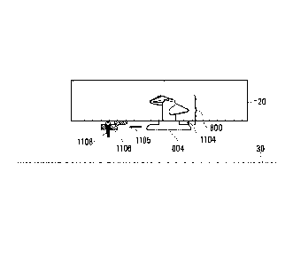
[0041] Figure 11 shows the rectangular panel bracket 800 installed into a
panel 20. The rectangular bottom
portion 804 as shown is flush against the substrate 30 (e.g. wall or ceiling).
The external threads 808 are
installed into the polyester panel 20. The wall or ceiling bracket 1106 is
affixed to the substrate 30 using a
mounting screw 1108. As previously discussed, the compression flange 806, when
completely seated in the
panel 20, separates the panel bracket 800 from the panel 20, and this
separation forms a recess 1104. The
recess 1104 on the rectangular panel bracket 800 engages with a corresponding
recess 1105 on the wall or
ceiling bracket 1106.
[0042] Figure 12 shows an example eye hook fastening device according to
another embodiment of the
present application. The eye hook fastening device 1200 comprises an eye hook
1201, a cylindrical structure
1202, a compression flange 1204, exterior threads 1206 extending from the
cylindrical structure 1202 and an
installation member 1208. The flange 1204 that is located on the tailing edge
of the cylindrical structure 1202
compresses the fiber of the polyester panel 20. This compression increases the
density of the fiber material
around the threads 1206 and the amount of pull-out force that can be applied
is increased significantly. Also,
the external threads 1206 are designed the same as threads 106. The threads
1206 design have been
specifically designed to create a high pull-out strength by embedding into
walls of the recess created in the
panel. The leading edge thread angle is high in relation to the thread angle
of the trailing edge. In an example
embodiment, the leading edge 1230 angle of the threads 1206 is 50 degrees or
higher, and the trailing edge
1232 angle of the threads is 20 degrees (or close to 20 degrees).
9
Date recue/ date received 2022-02-18
[0043] The eye hook 1201 is an opening that is shown as being circular in
shape, but it may be formed with
other shapes. One example application for using the eye hook fastening device
1200 are acoustical panels.
Acoustical panels are sometimes hung horizontally with the back face of the
panel facing toward the ceiling.
With the eye hook fastening device 1200, the eye hook 1201 is fixed or
integrated with the compression
flange 1204. This enables attachment of hanging hardware, chain, wire, or
other attachment means to the eye
hook 1201. The hook or hanging point can be represented as the eye hook 1201
shown in Figure 12, or can
be structured differently for example an open hook (e.g. not fully enclosed or
surrounded by the installation
member 1208).
[0044] The portion around the eye hook 1201 may function as the installation
turning member 1208. This
makes it possible to turn the exterior threads 1206 into the recess in the
back of the panel 20, far enough to
compress the panel fibers between the threads 1206 and the compression flange
1204.
[0045] In a further embodiment (not shown), a fastener with the same exterior
shape and configuration (e.g.
threads, cylindrical structure, flange) as the fastener part 100 shown in
Figure 1 is provided. With this
embodiment, the bottom (e.g. underneath) of the flange may be attached
directly to the substrate using
attachment means such as hook and loop (e.g. Velcro') or double sided tape.
[0046] As described in the above embodiments, the panel with the installed
fastener may be attached to the
substrate using various kinds of attachment means. The attachment means
engages with the bottom of the
flange and may be, for example, an anchor part (e.g. shown in Figure 3), a
substrate bracket (e.g. shown in
Figures 7 and 11), eye hook (e.g. shown in Figure 10), hook and loop
attachment or double-side tape. Other
attachment means may also be used.
[0047] All of the fastening devices and bracket assemblies described in the
application may be molded of
plastic material or other materials, such as die cast zinc, or machined metal
such as aluminum.
[0048] What has been described above includes examples of the disclosed
architecture. It is, of course, not
possible to describe every conceivable combination of components and/or
methodologies, but one of
ordinary skill in the art may recognize that many further combinations and
permutations are possible.
Accordingly, the novel architecture is intended to embrace all such
alterations, modifications and variations.
Furthermore, to the extent that the term "includes" is used in either the
detailed description or the claims,
Date recue/ date received 2022-02-18
such term is intended to be inclusive in a manner similar to the term
"comprising" as "comprising" is
interpreted when employed as a transitional word in a claim.
[0049] The foregoing descriptions of specific embodiments of the present
invention have been presented for
purposes of illustration and description. They are not intended to be
exhaustive or to limit the present
invention to the precise forms disclosed, and obviously many modifications and
variations are possible in
light of the above teaching. The exemplary embodiment was chosen and described
in order to best explain
the principles of the present invention and its practical application, to
thereby enable others skilled in the art
to best utilize the present invention and various embodiments with various
modifications as are suited to the
particular use contemplated.
11
Date recue/ date received 2022-02-18