Note: Descriptions are shown in the official language in which they were submitted.
CA 03149956 2022-02-04
WO 2021/028874 PCT/IB2020/057653
AIRFOIL PERFORMANCE MONITOR
CROSS-REFERENCE TO RELATED APPLICATIONS
[0001] The present application claims priority to and all the benefits of U.S.
Provisional
Patent Application No. 62/887,418 filed on August 15, 2019, which is hereby
expressly
incorporated herein by reference in its entirety.
BACKGROUND OF THE INVENTION
1. Field of the Invention
[0002] The present disclosure relates to an airfoil performance monitor, and
more
specifically, such a monitor that senses conditions at the working surface of
an airfoil.
2. Description of the Related Art
[0003] Aircraft are equipped with various sensors for providing real-time
feedback of
various operator controls. For example, sensors may be surface mounted to a
wing of an aircraft
in order to measure and provide data indicative of lift and drag across and
over an airfoil of the
wing. Measurements taken by sensors may account for contamination effects in
any
environmental conditions that the aircraft, and specifically the wing, may be
experiencing. The
sensors disposed on the wing of the aircraft allow actionable decisions to be
made to improve
performance of the airfoil of the wing. These airfoil performance sensors are
designed and
certified for aircraft wings to operate as a critical, life-saving sensor for
icing impact quantification.
[0004] In addition to fixed wing aircraft, airfoils are used in a number of
other applications
for various purposes. For example, the blade of a wind turbine is essentially
an airfoil. Air flowing
past the airfoil causes a lift force on that blade which in turn causes the
wind turbine to rotate,
thereby ultimately driving a generator from which electrical power is derived.
Currently, the
overall performance of a wind turbine is typically monitored using a "power
curve" which is a
measure of the electrical power produced by the turbine and is often related
to environmental
sensors such as the local wind speed. This method provides a gross overview of
the performance
1
CA 03149956 2022-02-04
WO 2021/028874 PCT/IB2020/057653
of the entire wind turbine, but it yields little insight into the specific
cause of any performance
losses, which might arise from aerodynamic, mechanical, electrical, or control
systems issues,
among others. Furthermore, the power curve yields no direct information about
the possible
aerodynamic degradation being experienced by one or more of the rotor blades
individually. Such
degradation can arise from numerous causes, including but not limited to
manufacturing defects,
leading-edge erosion (caused by sand, water or debris), acute damage (caused
by hail, lightning or
bird strike), or contamination by heavy rain, sleet, or accumulated ice
deposits. Icing is a
particularly serious problem, because its aerodynamic effects depend on so
many factors (e.g. ice
thickness, chordwise extent, vertical extent, spanwise extent, roughness,
etc.), that they are
essentially impossible to predict. The current state of the art includes the
use of icing detectors,
and even some icing thickness sensors, but none of these can predict the
effect of the measured ice
on the performance of the airfoils. Similar limitations apply to theoretical
efforts to determine the
impact of icing, such as Computational Fluid Dynamics techniques. As a result,
the common
approach to operation in icing conditions is to shut down the wind turbine,
which has serious
operational and financial consequences, because entire wind farms can be
simultaneously
impacted and shut down due to severe icing conditions. All of these factors
can have an
immediately deleterious effect on an individual wind turbine's performance,
but they can also lead
to reduced longevity, significantly increased maintenance costs, and higher
operating costs for an
entire wind farm because these problems are extremely difficult to isolate and
address with the
prior art.
SUMMARY OF THE INVENTION
[0005] The present invention is directed toward an airfoil performance monitor
that is
designed to overcome the deficiencies in the related art. Thus, one embodiment
of the airfoil
performance monitor of the present invention includes a housing that may be
mounted on a low-
pressure face of an airfoil. The housing includes at least one pitot pressure
orifice used to determine
the total pressure at the airfoil performance monitor and at least one static
pressure orifice used to
determine the static pressure at the airfoil performance monitor. The airfoil
performance monitor
includes at least one airspeed-dependent sensor that senses the total pressure
at the airfoil
performance monitor via the pitot pressure orifice and generates a digital
airflow signal indicative
2
CA 03149956 2022-02-04
WO 2021/028874 PCT/IB2020/057653
of the dynamic pressure at the airfoil performance monitor. A controller
derives a turbulence
intensity ratio by processing and filtering turbulence values calculated from
the digital airflow
signal.
[0006] The present invention is also directed toward an airfoil performance
monitor system
that includes at least one airspeed-dependent sensor disposed on a low-
pressure face of an airfoil.
The air foil performance monitor system includes at least one pitot pressure
sensing orifice used
to determine the total pressure at the airfoil performance monitor and at
least one static pressure
orifice disposed on a low-pressure face of an airfoil used to determine the
static pressure at the
airfoil performance monitor. At least one airspeed-dependent sensor measures
the total pressure
at the pitot pressure orifice and generates a digital airflow signal
indicative of the dynamic pressure
measured at the at least one pitot pressure orifice.
[0007] The signal generated from an airspeed-dependent sensor is processed
into a digital
airflow signal indicative of turbulence of the airflow. Additionally, the
airfoil performance
monitor system of the present invention includes one or more inertial sensors
that measure
acceleration, or other motions, in up to three orientations in relation to the
mounting point. A
controller derives a turbulence intensity by normalizing the measured
turbulence intensity using
the steady-state airflow signal, thereby generating a non-dimensional
turbulence intensity ratio of
the turbulent to steady state signal components. The controller also filters
the signals from the
airflow- dependent sensors using the frequencies obtained from the inertial
sensors to eliminate
the unwanted blade vibration effects on the turbulence intensity calculations.
[0008] A controller uses the processed turbulence intensity signal to monitor
the
aerodynamic performance of the airfoil, and to prevent a pre-set turbulence
intensity threshold
being exceeded which would be indicative of an airfoil "stall" as discussed
below.
[0009] In addition, the present invention is directed toward an airfoil
performance monitor
system for use with a wind turbine. The system includes a housing mounted on a
low-pressure face
of an airfoil. The housing defines at least one pitot and one static pressure
orifice. At least one
airspeed-dependent sensor is disposed on a low-pressure face of an airfoil.
The signal generated
from the airspeed-dependent sensor as a result of airflow measured via the
pitot-static orifices is
processed into a digital signal indicative of the turbulence of the airflow.
One or more inertial
sensors measure a blade pitch angle, and motion in up to three orientations
from their mounting
location based on mechanical motion of the airfoil transmitted mechanically to
the housing. A
3
CA 03149956 2022-02-04
WO 2021/028874 PCT/IB2020/057653
controller derives a turbulence intensity ratio by filtering turbulence values
with the acceleration
in response to the blade pitch angle and the frequency and amplitude of the
acceleration from the
one or more inertial sensors and relating the filtered airflow turbulence
signal to the steady state
airflow signal, and generates data upon which commands are based to adjust the
blade pitch angle
using a rotor control system.
[0010] The present invention is also directed toward a wind turbine that
includes one or
more blades that turn a shaft, a generator, which may be connected via a
gearbox to the shaft, that
converts and stores energy, and a housing mounted on a low-pressure face of an
airfoil. The
housing defines at least one pitot pressure orifice used to measure the total
pressure at the airfoil
performance monitor and at least one static pressure orifice used to measure
the static pressure at
the airfoil performance monitor. At least one airspeed-dependent sensor is in
fluid communication
with the at least one pitot pressure orifice that converts airflow measured
via the pitot orifice and
generates a digital airflow signal indicative of turbulence of the airflow.
One or more inertial
sensors are disposed on a low pressure face of an airfoil of one of the blades
that may measure a
blade pitch angle, and acceleration, which is frequency and amplitude data
measured in up to three
orientations from the mounted location on one or more of the blades. A
controller derives a
turbulence intensity ratio by relating the filtered turbulence signal to the
steady state airflow signal
and generates commands to adjust the blade pitch angle using a rotor control
system.
[0011] Other objects, features and advantages of the present invention will be
readily
appreciated as the same becomes better understood after reading the subsequent
description taken
in connection with the accompanying drawings.
BRIEF DESCRIPTION OF THE DRAWINGS
[0012] Figure 1 is a perspective view of a wind farm with a plurality of wind
turbines;
[0013] Figure 2 is a side view of a wind turbine and rotor assembly;
[0014] Figure 2A is an enlarged cross-sectional side view depicting an airfoil
defined by a
turbine blade;
[0015] Figure 3A is a schematic view of a rotor for a wind turbine with a
blade having a
mast-mounted sensor assembly;
[0016] Figure 3B is a schematic view of the mast-mounted sensor assembly;
4
CA 03149956 2022-02-04
WO 2021/028874 PCT/IB2020/057653
[0017] Figure 4 is perspective view of a mounting interface for the mast-
mounted sensor
assembly;
[0018] Figure 5 is a cross-sectional view of one embodiment of the mast-
mounted sensor
assembly of the present invention;
[0019] Figure 6 is a perspective view of an additional embodiment of a mast-
mounted
sensor assembly;
[0020] Figure 7 is a functional block diagram for the mast-mounted sensor
assembly;
[0021] Figure 8 is a flow chart depicting operation of the mast-mounted sensor
assembly;
and
[0022] Figure 9 is a flow chart depicting operation of a heater for the mast-
mounted sensor
assembly.
DETAILED DESCRIPTION OF THE INVENTION
[0023] As described in greater detail below, the present invention is directed
toward an
airfoil performance monitor. As a means of illustrating the inventive features
of the present
invention, the performance monitor is described with respect to use in
connection with wind
turbines. However, those having ordinary skill in the art will appreciate from
the description that
follows that this is only one representative example of how the performance
monitor of the present
invention may be employed to monitor and track environmental and operational
performance
conditions at an airfoil used in any number of applications.
[0024] With this representative, environmental application in mind, Figure 1
depicts one
representative perspective view of a wind farm 10 having a plurality of wind
turbines 12. The
wind turbines 12 are arranged in an array 14. The wind turbines 12 convert
kinetic energy from
wind into electrical energy, by way of an electro-mechanical system. As will
be described in more
detail below, wind flows across each wind turbine 12 within the array 14,
which causes blades 16
of each of the wind turbines 12 to turn. Turning the blades 16 transfers
kinetic energy from wind
into the mechanical power, which can be used to rotate a generator that
produces electricity that
can be stored or transmitted to an electrical grid as electrical energy from
the wind turbine 12.
Therefore, each of the plurality of wind turbines 12 may be disposed in an
array 14 arranged based
on wind patterns to enhance and maximize energy conversion within the wind
turbines 12.
CA 03149956 2022-02-04
WO 2021/028874 PCT/IB2020/057653
[0025] As shown, the array 14 of plurality of wind turbines 12 is oriented
such that each
of the wind turbines 12 has adequate spacing to allow the blades 16 to turn,
while maximizing an
amount of individual wind turbines 12 within the array 14. Stated differently,
a distance 18
between each of the turbines 12 may be set to maximize a number of wind
turbines 12 disposed
within the array 14 of the plurality of wind turbines 12. Additionally, in
order to cause the blades
16 of the wind turbines 12 to rotate, the wind turbines 12 planes of rotation
need to be oriented in
a direction substantially perpendicular to the direction of the wind. While
described as
substantially perpendicular, the orientation of each of the wind turbines 12
may be within a range
of angles dependent on the direction and patterns of wind that flows through
the wind farm 10 to
allow the blades 16 to turn with optimal efficiency.
[0026] The array 14 of wind turbines 12 may be arranged in a shape designed to
optimize
an amount of wind turbines 12 in the plurality of wind turbines 12 disposed
within the array 14 of
the wind farm 10. The shape of the array 14 of wind turbines 12 disposed and
arranged on the
wind farm 10 may be based, at least in part, on the distance 18 needed between
each of the other
wind turbines 12 to allow the blades 16 full rotation, as described above, and
a pattern and direction
of wind as it passes through the wind farm 10. Additionally, a fore and aft
distance 20 between
each turbine 12 within the plurality of turbines 12 may impact the shape and
orientation of the
array 14 of the plurality of wind turbines 12. For example, minimizing the
fore and aft distance
20, as well as the distance 18 between each of the wind turbines 12 may
maximize a number of
wind turbines 12 disposed within the array 14.
[0027] Likewise, an optimized fore and aft distance 20 and distance 18 between
each of
the wind turbines 12 may impact the shape of the array 14 to maximize
efficiency of the wind farm
10. Optimizing the fore and aft distance 20 between each of the wind turbines
12 may also consider
a strength, direction and pattern of wind across the wind farm 10. Stated
differently, the direction
and pattern of wind blowing across the array 14 of wind turbines 12 may
further provided data
indicative of an optimal fore and aft distance 20 between each of the wind
turbines 12 within the
array 14 to maximize an efficiency of each of the wind turbines 12 in the
array 14.
[0028] Referring to Figure 2, a side view of an individual wind turbine 12 is
depicted. The
wind turbine 12 may include a generally vertical tower 13 that supports a
housing, sometimes
referred to as a nacelle, 15 which, in turn, supports internal components of
the turbine, such as a
generator 32, gearbox 30, associated shafts, yaw drive, yaw motor and the
like. The housing 15
6
CA 03149956 2022-02-04
WO 2021/028874 PCT/IB2020/057653
includes a rotor 24 that comprises a hub 33 to which are mounted wind turbine
blades 16. The
wind turbine 12 depicted in Figure 2 is shown having individual blades 16.
Each turbine 12 may
include a plurality of blades 16 based on an optimal number of blades 16 to
maximize efficiency
of energy generation by the wind turbine 12. The number of blades 16 arranged
on the wind
turbines 12 may also be determined based on the direction and pattern of wind
blowing across the
wind farm 10 to maximize efficiency of energy generation by the wind turbines
12 across the array
14 of wind turbines 12. The blades 16 are arranged on the wind turbine 12 such
that, in response
to wind flowing through the wind turbine 12, the blades 16 rotate around a
horizontal axis 22 that
intersects a centerline 25 of the rotor 24 of the wind turbine 12.
[0029] Specifically, wind flowing across each blade 16 is separated such that
the blades 16
define high and low pressure sides 27, 29. The blades 16 turn in response to
the pressure difference
between the high and low pressure sides 27, 29. For example, the pressure
difference from the
high pressure side 27 to the low pressure side 29 provides a force necessary
to accelerate the blades
16 on the rotor 24 to turn a shaft 28 that converts a mechanical torque from
the wind energy into
electrical energy by a generator 32, as will be described in more detail
below. The rotor 24 may
be controlled by a rotor control system 23 that is adapted to adjust a
position and orientation of the
blades 16 relative to the centerline 25 of the rotor 24. For example, the
rotor control system 23
may adjust a pitch angle 36 of the blades 16 to optimize performance of the
wind turbine 12.
[0030] The rotor 24 rotates the shaft 28 disposed within the housing 15 of the
wind turbine
12. The shaft 28 may transfer torque from the rotor 24 through a gearbox 30
connected to the
generator 32 or may be directly connected to the generator 32. The generator
32 converts torque
into electrical energy, which can be stored for later use or transmitted to an
electrical grid.
Therefore, as wind flows across the wind turbine 12 and causes the blades 16
to rotate, as
described, the rotor 24 rotates the shaft 28 to transfer power to the
generator 32, which produces
electrical energy for use. The more revolutions of the shaft 28 by the blades
16 turning the rotor
24, the more electrical energy that is produced by the generator 32. Stated
differently, performance
of the blades 16 dictate an amount of electrical energy converted by the
generator 32, and providing
adjustment to an orientation 34 of the blades 16 and a pitch angle 36 of each
blade 16 may further
aid to improve performance of each of the blades 16. Additionally, in at least
one other
embodiment, a coning angle 38 between each blade 16 may be based on optimal
parameters from
the strength, direction and pattern of wind blowing across the wind turbine
12.
7
CA 03149956 2022-02-04
WO 2021/028874 PCT/IB2020/057653
[0031] The pitch angle 36 of each blade 16 aids the blade 16 in turning the
rotor 24. The
inventors have found that monitoring the pitch angle 36 of each blade 16 and
providing
adjustments to maximize efficiency is advantageous. For example, as wind flows
past the wind
turbine 12 and across the blades 16 of the wind turbine 12, the pitch angle 36
of the blade 16 forces
air to travel around an airfoil 40 of the blade 16, as previously described.
The movement of air
around the airfoil 40 of the blade 16 propels the blade 16 around the rotor
24. Therefore, the pitch
angle 36 of the blade 16 aids in determining efficiency and production of
mechanical power
transfer through the rotor 24 and shaft 28 into electrical energy converted by
the generator 32.
[0032] Each blade 16 includes a span length 42 as well as a chord length 43.
The chord
length 43 is a length of a cross-section of the blade 16, as measured from the
leading edge 45 to
the trailing edge 47 of the blade 16 cross-section. As wind flows across the
blades, the resulting
forces on the blade cause a torque to be applied to the rotor 24 which spins
the shaft 28 connected
to the generator. The wind turbine control system adjusts the pitch angle 36
of the blades 16 to
optimize the performance of the wind turbine for the extant wind conditions,
while keeping the
wind turbine within its design operating limits (e.g. RPM, structural loads,
etc.). As will be
discussed in more detail below, the airfoil performance monitor and system of
the present
invention disposed on the blade 16 aids the control system in improving the
overall performance
of the wind turbine 12 under a broad range of operating conditions, including
the presence of airfoil
degradations such as those caused by leading edge erosion or icing, generally
indicated at 49 in
Fig. 2A.
[0033] Figures 3A and 3B depict a perspective view of the blade 16 detached
from the
rotor 24 and wind turbine 12. Figure 3A depicts one operative embodiment where
the blade 16
has four airfoil performance monitors 44 disposed between the blade root and
blade tip 46, 48, and
wherein the blade 16 attaches to the rotor 24 at the root 46. The blade 16
attaches to the rotor 24
at the root 46 using one or more fasteners (not shown). Alternatively, the
blade 16 may attach to
the rotor 24 at the root 46 using any known mechanical fastening technique.
The airfoil
performance monitor 44 may also be referred to as an airfoil performance
monitor system 44. As
will be described in more detail below, the airfoil performance monitor 44 may
be mounted on a
low-pressure face 52 of the airfoil 40. Securing the airfoil performance
monitor 44 on a low-
pressure face 52 of the airfoil 40 allows the airfoil performance monitor 44
to provide data
indicative of a performance of the blade 16 of the wind turbine 12.
8
CA 03149956 2022-02-04
WO 2021/028874 PCT/IB2020/057653
[0034] As shown, the airfoil performance monitor 44 may be spaced along the
blade 16
between the blade root and blade tip 46, 48. The airfoil performance monitor
44 may be secured
to the blade 16 at distinct, predetermined positions 54, or may be spaced
according to a set,
predetermined pattern (not shown). For example, depending on the shape and
design of the wind
turbine blade 16 or on wind patterns, direction and strength, as well as a
design of the array 14 of
wind turbines 12, the airfoil performance monitors 44 may be secured at the
predetermined
position 54 indicative of providing the airfoil performance monitor 44 a data
set, that may be
utilized to optimize the performance of the blade 16 and wind turbine 12. The
predetermined
position 54 of the airfoil performance monitor 44 may be determined by
computational fluid
dynamics analysis and/or by experimentation during initial setup to ensure the
predetermined
position 54 provides the best available data to the airfoil performance
monitor 44 to optimize a
performance of the wind turbine 12.
[0035] Alternatively, the airfoil performance monitor 44 may be evenly spaced
between
the root and tip 46, 48 of the blade 16. For example, the airfoil performance
monitors 44 may
define an equal distance 56 between centers 58 of each of the airfoil
performance monitors 44
disposed on the blade 16. Providing equal distance 56 between centers 58 of
each of the airfoil
performance monitors 44 allows the airfoil performance monitor 44 to collect
data in evenly
distributed sections 60 across the blade 16. Collecting data in distributed
sections 60 provides
performance information of the airfoil 40 of the blade 16 as wind acts to
rotate the blades 16 about
the rotor 24. This data indicative of performance of the blade 16 at each
section 60 allows the
airfoil performance monitor 44 to provide accurate analysis of the interaction
between the blade
16 and wind acting across the blade 16, and likewise aid to optimize
performance and efficiency
of each individual blade 16 on the wind turbine 12 for greater production of
electrical energy from
the wind farm 10.
[0036] As noted above, the embodiment shown in Figure 3A includes four airfoil
performance monitors 44 secured to the blade 16. However, this is merely
exemplary. The blade
16 may employ any number of airfoil performance monitors 44 secured between
the root and tip
46, 48 of the blade 16. The number of airfoil performance monitors 44 secured
to the blade 16
may be dependent on the shape and design of the wind turbine blade 16, and/or
the direction,
pattern and strength of wind that interacts with the blade 16. The number of
airfoil performance
monitors 44 may also be dependent on an amount of data necessary to calculate
and optimize a
9
CA 03149956 2022-02-04
WO 2021/028874 PCT/IB2020/057653
performance of the blade 16 and wind turbine 12. For example, a single airfoil
performance
monitor 44 may provide enough data and processing power to effectively
calculate and adjust a
performance of the blade 16 such that production of wind energy is optimized.
Likewise, multiple
airfoil performance monitors 44, as shown, may provide additional data to
increase a sensitivity of
the overall performance of the airfoil performance monitor system 44.
[0037] Referring to Figure 3B, a schematic view of one embodiment of the
airfoil
performance monitor 44 is depicted. As shown in Figure 4, the airfoil
performance monitor 44
includes a housing or mast 50. The mast 50 defines a fin portion 62 and a base
portion 64. The
fin portion 62 extends in a direction perpendicular from the airfoil 40 from
the base portion 64.
The base portion 64 attaches to the airfoil using mechanical fasteners (not
shown) extending
through a plurality of holes 66 defined through the base portion 64. However,
those having
ordinary skill in the art will appreciate that the base portion 64 may be
mounted to the airfoil using
any conventional fastening mechanism. The fin portion 62 attaches to the base
portion 64 through
welding, forming, adhesion or any other known mechanical joining technique
such that the fin
portion 62 is sealed to the base portion 64. Alternatively, the fin and base
portions may be formed
as an integral, one-piece component. The base portion 64 may be substantially
solid and formed
to provide as much surface area contact between the base portion 64 and the
airfoil 40 to ensure
greater stability of the mast 50 on the blade 16. The fin portion 62 is formed
as substantially
hollow, and may be of a streamlined airfoil shape such that air flows on each
side 68 of the fin
portion 62, as shown in Figure 3B Alternatively, the fin may be manufactured
as an integral part
of the wind turbine blade 16, in which case the fin portion 62 would be
integrated into the wind
turbine blade 16 foregoing the need for the base portion 64 attachment.
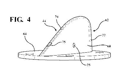
[0038] Figure 4 depicts a perspective view of the fin housing or mast 50 of an
airfoil
performance monitor 44 that includes fin 62 and base portions 64. The fin
portion 62 is designed
to house components of the airfoil performance monitor 44. For example, Figure
5 depicts a
schematic, perspective, cross-sectional view of one embodiment of the airfoil
performance monitor
44 as a single combined unit that houses all of the necessary electronics in
the mast. Specifically,
Figure 5 depicts an interior 76 of the combined airfoil performance monitor
44. And as will be
described in more detail below with respect to Figure 5, the fin portion 62 is
designed to house at
least one or more inertial sensors 70, such as accelerometers, one or more
airspeed-dependent
CA 03149956 2022-02-04
WO 2021/028874 PCT/IB2020/057653
sensors 78, a controller 72 and associated electronics to provide data
indicative of a performance
and efficiency of the airfoil 40 for the blade 16 of the wind turbine 12.
[0039] In one embodiment shown in Figure 5, the fin portion 62 defines at
least one pitot
pressure orifice 74 and at least one static pressure orifice 75. However, the
airfoil performance
monitor 44 of the present invention may include a plurality of pitot orifices
74 and a plurality of
static pressure orifice 75. For example, in the embodiment shown in Figure 5,
the pitot pressure
orifice 74 is disposed on the front or leading edge 77 of the fin portion 62
and the static pressure
orifice 75 is located on the trailing edge 79 of the fin portion 62. On the
other hand, and as shown
in Figure 4, the airfoil performance monitor 44 may include a plurality of
static pressure orifices
75. One of the static pressure orifices may be located on the side 68 of the
fin portion 62 and
another may be located on the trailing edge 79 of the fin portion 62. These
embodiments are
merely exemplary, and the amount and location of pitot and static orifices 74,
75 may vary between
depending, for example, on airflow strength, pattern and direction at a
location of the mast 50. The
size and shape of the pitot and static orifices 74, 75 may be adjusted to
adjust the exposure of the
airflow dependent sensor and tune the sensitivity necessary to calculate a
performance and
efficiency of the blade 16 of the wind turbine 12. The pitot and static
pressure orifices 74, 75 may
also be disposed at a 45 degree angle relative to a horizontal plane passing
through the fin portion
62 to facilitate drainage of any liquid, such as water from rain or melting
snow or ice, from the
mast 50.
[0040] Each of the pitot pressure orifices 74 is in fluid communication with
at least one
airspeed-dependent sensor 78. The static pressure orifices 75 may also be in
fluid communication
with at least one airspeed-dependent sensor 78 as well. Alternatively, the
static pressure orifice
75 may be in fluid communication with the interior 76 of the mast 50 such that
the pressure of the
interior of the mast 50 reflects the external static pressure. In this
configuration, the static pressure
orifices are simply open to the interior 76 of the mast 50 to equalize the
internal and static external
pressure. The pitot orifice 74 and its associated airspeed-dependent sensor 78
is used to measure
total pressure that impinges upon the pitot orifice 74. The static pressure
orifice 75 is used to
measure the static pressure that impinges on the static orifice 75. As will be
discussed in greater
detail below, the static pressure measured at the static pressure orifice 75
is subtracted from the
total pressure measured at the pitot pressure orifice 74 to arrive at the
dynamic pressure.
11
CA 03149956 2022-02-04
WO 2021/028874 PCT/IB2020/057653
[0041] With continuing reference to Figure 5, one or more inertial sensors 70,
and one or
more airspeed-dependent sensors 78 are shown stacked above the controller 72
within the interior
76 of the fin portion 62 of the mast 50. In the embodiment shown in Figure 5,
the inertial sensors
70 may be accelerometers. However, those having ordinary skill in the art will
appreciate that any
type of inertial sensor suitable for the purposes disclosed herein are
acceptable. Stacking the
inertial sensors 70, the airspeed-dependent sensors 78, and the controller 72
allows the mast 50 to
efficiently package electronics necessary to optimize a performance and
efficiency of the wind
turbine 12.
[0042] The inertial sensors in the form of accelerometers 70 may be disposed
above the
airspeed-dependent sensors 78, which are located above the controller 72 in
the embodiment
illustrated in the figures. As noted above, however, those having ordinary
skill in the art will
appreciate that these components may be arranged relative to each other in any
number of
configurations without departing from the scope of the present invention. This
arrangement is
merely exemplary. In at least one other embodiment, the airspeed-dependent
sensors 78 may be
disposed above the accelerometers 70, which are located above the controller
72. Likewise, the
controller 72 may be stacked above both the accelerometers 70 and the airspeed-
dependent sensors
78. The combination and orientation of the accelerometers 70, airspeed-
dependent sensors 78, and
controller 72 may be optimized by sensor type, efficiency and performance
requirements. For
example, the airspeed-dependent sensors 78 may be disposed in an orientation
and stacked within
the interior 76 of the mast 50 such that airflow measured via pitot orifices
74 in the mast 50 provide
airspeed-dependent data accurately sensed by the airspeed-dependent sensors
78. In the same way,
the accelerometers 70 may be disposed in an orientation and stacked within the
interior 76 of the
mast 50 such that an angle, or pitch of the airfoil performance monitor 44
provides acceleration
data of the blade 16 accurately sensed by the accelerometers 70. Similarly,
the controller 72 may
be disposed and stacked within the interior 76 of the mast 50 in an
orientation that provides
efficient data processing and transfer.
[0043] The airspeed-dependent sensors 78 may be pressure sensors. The pressure
sensors
used as airspeed-dependent sensors 78 may be sensors with a high frequency
response, such as,
but not limited to, piezo-resistive, thin film sensors. Any other type of
pressure sensor, for example
sealed and unsealed, that is adapted to measure differential airflow pressure
or velocity may also
be contemplated by one having ordinary skill in the art. Likewise, the
inertial sensors, such as
12
CA 03149956 2022-02-04
WO 2021/028874 PCT/IB2020/057653
accelerometers 70, may be sensors that measure vibration of the blade 16. The
accelerometers 70
may be either high or low impedance piezoelectric sensors. As noted above, he
accelerometers 70
may be substituted with, or supplemented by, alternative inertial measurement
sensors to also
include 6-axis or 3-axis gyroscopes adapted to measure vibration from the
blade 16 through the
mast 50. Operation of the inertial sensors 70, airspeed-dependent sensors 78
and controller 72 will
be explained in more detail with reference to the other Figures.
[0044] The airfoil performance monitor illustrated in Figure 5 also includes
heater
elements 80. Heater elements 80 may be supported within the interior 76 of the
mast 50 on either
side of the accelerometers 70, the airspeed-dependent sensors 78 and the
controller 72. While
shown and described as being disposed on either side of the accelerometers 70,
the airspeed-
dependent sensors 78 and the controller 72, the heater elements 80 may be a
single heater element
80 disposed on a single side from the accelerometers 70, the airspeed-
dependent sensors 78 and
the controller 72. The heater elements 80 may be any element adapted to
radiate heat into the mast
50, such as, but not limited to, a resistive heating element 80 that produces
heat in response to
electrical current. The heater elements 80 are configured to keep the mast 50,
the accelerometers
70, the airspeed-dependent sensors 78, and controller 72 from accumulating ice
on the mast 50 and
obstructing the pitot and static orifices 74, 75 during adverse weather
conditions.
[0045] The mast 50 may also include a power supply 82 disposed within the
interior 76 of
the mast 50. The power supply 82 may be on a single side of the interior 76 of
the mast 50 or
disposed on either side of the interior 76 of the mast 50, depending on an
amount of power needed.
The power supply 82 is adapted to provide electrical power to the
accelerometers 70, the airspeed-
dependent sensors 78 and the controller 72 depending on required power use of
the accelerometers
70, airspeed-dependent sensors 78, the controller 72 and the heaters 80. Power
provided by the
power supply 82 may be optimized based on a type of accelerometer 72, airspeed-
dependent
sensors 78, heaters 80 and processing requirements of the controller 72.
[0046] Figure 6 depicts another embodiment of the airfoil performance monitor
44 wherein
the controller 72 is separated from the accelerometers 70 and airspeed-
dependent sensors 78. By
separating the controller 72 from the accelerometers 70 and airspeed-dependent
sensors 78, a
smaller footprint for the mast 50 may be achieved. Additionally, with the
controller 72 separated
from the accelerometers 70 and airspeed-dependent sensors 78, the mast 50 has
greater mounting
flexibility on the blade 16 of the wind turbine 12 based on this smaller
footprint. Specifically, in
13
CA 03149956 2022-02-04
WO 2021/028874 PCT/IB2020/057653
the embodiment shown in Figure 6, the mast 50 may include the pitot and static
orifices 74, 75,
the accelerometers 70 and the airspeed-dependent sensors 78. The controller 72
may be disposed
remote from the mast 50 shown in Figure 6. As shown, the controller 72 is
disposed beneath the
mast 50. This is merely exemplary, and indicative of the controller 72 being
remote from the mast
50. Again, Figure 6 depicts a further embodiment of the airfoil performance
monitor 44 that allows
for a mast 50 with a smaller footprint, providing ease of installation for the
mast 50 on the blade
16.
[0047] Referring to Figure 7, a functional block diagram of operation of the
airfoil
performance monitor 44 is depicted. The functional block diagram shown in
Figure 7 depicts
interaction between the accelerometers 70, airspeed-dependent sensors 78
disposed within the
mast 50, the controller 72, and a display 84. As can be seen in the embodiment
depicted in Figure
7, the mast 50 includes the airspeed-dependent sensors 78, the accelerometers
70, and the heater
elements 80. As will be described in more detail with reference to the other
Figures, the heater
elements 80 may be operated as a closed loop with a switch 86 such that the
switch 86 is used to
regulate heat from the heater elements 80. As shown, for example, the heater
elements 80 receive
approximately 28 volts of direct current to operate. This is merely exemplary,
however, and the
required volts to operate the heater elements 80 may be more or less than 28
volts depending on
the type and arrangement of the heater elements 80.
[0048] Figure 7 also depicts the accelerometers 70 and airspeed-dependent
sensors 78 in
communication with the controller 72. As shown, the airspeed-dependent sensors
78 send sensor
voltage data produced by, and indicative of an airflow pressure and velocity
measured via the pitot
pressure orifice 74 and possibly the static pressure orifices 75. The inertial
sensors 70, such as
accelerometers, provide acceleration data indicative of the mechanical motion
of the blade 16 and
can be used to infer the pitch angle 36 of the blade 16 of the wind turbine
12. Both the acceleration
data from the inertial sensors 70 and the sensor voltage data from airspeed-
dependent sensors 78
are used by the controller 72 to calculate a turbulence value of airflow
across the blade 12.
Specifically, the acceleration data, as will be described in more detail
below, from the inertial
sensors 70 is used to filter vibratory noise detected by the airfoil
performance monitor 44, and the
sensor voltage data from the airspeed-dependent sensors 78 is used to
calculate the dynamic
pressure at the blade 16 of the wind turbine 12. Again, as can be seen in
Figure 7, the power supply
82 connects to the sensors in the mast 50, and specifically the airspeed-
dependent sensors 78 to
14
CA 03149956 2022-02-04
WO 2021/028874 PCT/IB2020/057653
provide power to the mast 50. As shown, the power supply 82 supplies 28 volts
of direct current
to the airspeed-dependent sensors 78. The airspeed-dependent sensors 78 may
also be adapted to
be powered on any amount of voltage from the power supply 82.
[0049] The controller 72 is also in communication with the inertial sensors
70, airspeed-
dependent sensors 78 and power supply 82. The power supply 82 is adapted to
supply power to
the controller 72 to allow the controller 72 sufficient processing power to
compute a digital airflow
signal. Ultimately, the controller 72 is configured to calculate a filtered
turbulence airflow signal.
The turbulence airflow signal is used to calculate an airflow, turbulence
intensity ratio, as will be
described in greater detail with reference to the other figures. Specifically,
the airspeed-dependent
sensors 78 provide data indicative of the total pressure at the blade 16 as
measured at the pitot
orifices 74 of the airfoil performance monitor 44. The static pressure
orifices 75 are used to
measure the static pressure at the airfoil performance monitor 44. The
measured static pressure is
subtracted from the total pressure to arrive at the dynamic pressure at the
airfoil performance
monitor 44. The inertial sensors 70 provide data indicative of vibration
frequency and amplitude
of vibrations on the blade 16 through the mast 50 to the controller 72 to
calculate the turbulence
intensity ratio. Additionally, data from the inertial sensors 70 is corrected
for an orientation of the
blade 16 by a blade incidence angle (not shown), if necessary, such that a
characteristic, vibration
frequency and amplitude are extracted from the filtered turbulence signal
using the controller 72.
To account for the blade pitch angle 36, a gain is set in the controller 72
since the blade pitch angle
36 may be set at an arbitrary pitch angle independent of the local airspeed.
[0050] The vibration frequency and amplitude data from the inertial sensors 70
is used to
filter the digital airflow signal derived from data indicative of turbulent
airflow from the airspeed-
dependent sensors 78 to eliminate noise caused by vibration of the mast 50 on
the blade 16 of the
wind turbine 12. Specifically, as air impinges on the pitot and static
orifices 74, 75 the airspeed-
dependent sensors 78 are excited by an increase in turbulence as an angle-of-
attack of the blade 16
increases to generate an alternating current (hereinafter "AC") signal being
data indicative of
turbulent airflow. A change in the blade 16 aerodynamics from contamination,
damage, defect, or
other airflow modifying cause(s) may also increase the turbulence of the
airflow. The airspeed-
dependent sensors 78 are excited by this increase in turbulence to generate an
AC signal being data
indicative of turbulent airflow. In the absence of mechanical vibration, the
inertial sensors 70
CA 03149956 2022-02-04
WO 2021/028874 PCT/IB2020/057653
provide a relatively small or zero oscillatory signal due the lack of
mechanical motion of the blade
16, and the AC signal can be determined to be accurately indicative of an
increase in turbulence.
[0051] Conversely, if mechanical motion, such as vibrations, are induced on
the blade 16,
the mechanical motion relative to the airflow measured at the pitot and static
orifices 74, 75
generates an AC signal falsely indicative of increased turbulence. The
inertial sensors 70 are
adapted to register, as frequency and amplitude data, mechanical motion during
vibratory
oscillations in order that the frequency of these spurious vibration-induced
turbulence signals can
be determined and filtered out from the airflow signal. As described, the
controller 72 is
configured to identify and filter the frequency and amplitude data indicative
of mechanical motion
on the blade 16 from the AC signal such that the filtered digital airflow
signal can be determined
to be accurately indicative of an increase in turbulence. The controller 72
may include a filter that
can employ Fast Fourier Transform methods to identify the characteristic
frequencies induced by
mechanical vibrations. The filters may include notch, band-pass, high-pass,
low-pass, low-pass
parabolic or any other filter(s) to filter the undesired vibration-induced
signals from the digital
airflow signal to arrive at a correct measure of the airflow turbulence. More
specifically, the
controller 72 may apply Fast Fourier methods to the accelerometer signals to
determine the
fundamental vibratory frequencies of the unwanted noise induced by mechanical
vibrations of the
airfoil performance monitor 44 at the mast 50. The controller 72 then uses
filtering techniques
which could include, but are not limited to, one or more of a notch, band-
pass, high-pass, low-
pass, or low-pass parabolic filters to eliminate the unwanted vibration-
induced noise from the
desired air turbulence signal. During steady-state conditions, in which
airflow measured via the
pitot and static orifices 74, 75 is laminar and the blade 16 is not vibrating,
both signals provide
minimal signals of turbulence or motion, which is indicated by the smooth
direct current
(hereinafter "DC") component of the digital airflow signal.
[0052] The controller 72 normalizes the filtered frequency and amplitude AC
signal by
dividing by a DC component of the frequency and amplitude data from the
airspeed-dependent
sensors 78. The controller 72 also normalizes the inputs from the one or more
inertial sensors 70,
such as accelerometers, into acceleration components parallel to and
perpendicular to the plane of
rotation of the rotor 24 in response to a blade pitch angle 36. The controller
72 calculates a
turbulence intensity ratio R by dividing an alternating airflow component, the
AC signal, by a
steady-state component, the DC signal. Each airfoil performance monitor 44,
therefore, generates
16
CA 03149956 2022-02-04
WO 2021/028874 PCT/IB2020/057653
a turbulence intensity ratio R at a position of the mast 50 on the blade 16.
The controller 72
compares the turbulence intensity ratios R from each of the masts 50 disposed
along the blade 16
to a threshold turbulence intensity ratio R', which is specific to the
location of each airfoil
performance monitor and airspeed-dependent sensor associated with a given
pitot pressure orifice,
that represents the desired stall warning threshold for the blade section at
that location. The
wholesale separation of the airflow from the low pressure side 29 of the
affected section of the
airfoil which leads to a rapid reduction in blade propulsive force accompanied
by a rapid increase
in blade drag that can have a severe effect on the operation of the wind
turbine. The unsteady
airflow characteristics that usually accompany a stall may also lead to severe
vibrations that can
jeopardize the integrity of the wind turbine, and which certainly would impact
the wear and tear
experienced by the drive components.
[0053] A stall may be caused by operation at too high a blade pitch angle 36,
or due to
environmental factors such as icing, which degrades the airflow over the
airfoil leading to a
premature stall at an otherwise "safe" blade pitch angle 36. The stall is
always accompanied by an
increase in the relative turbulence seen on the low-pressure side 29 as the
lift on the blade begins
to decrease. The stall phenomenon for rotating airfoils is complex. Different
spanwise portions of
a wind turbine airfoil may be stalled at different times; one blade may be
stalled while another is
not (for example if ice is shed asymmetrically from different blades); and the
stall phenomenon
may be cyclic ¨ for example each blade might stall as it rotates past the wind
turbine tower. It is
exactly these phenomena that the proposed invention addresses.
[0054] In the case of the wind turbine 12, stall conditions that reduce the
blade 16 lift
reduce rotational efficiency as the blade 16 turns around the rotor 24. Stated
differently, the term
stall refers to the reduction of lift and increased drag created by the
collapsing pressure differential
between the low pressure side 29 and the high pressure side 27 of the blade
16, due to excessive
angle-of-attack of the blade 16, which causes significantly increased
turbulence on the low
pressure side 29 of the blade 16. In extreme cases, these conditions may cause
the blade 16
rotational efficiency to drop below the level required to keep the rotation of
the wind turbine self-
sustaining. The controller 72 may be further configured to adjust the
threshold R' to account for
varying circumstances. For example, the controller 72 may use a blade pitch
angle 36 measured
with the accelerometers 70 to scale the turbulence intensity ratio R to adjust
the threshold R' as a
function of an angle of the blade 16.
17
CA 03149956 2022-02-04
WO 2021/028874 PCT/IB2020/057653
[0055] The controller 72 may also be configured to transfer data indicative of
the
turbulence intensity ratio R through a variety of interfaces. As shown in
Figure 7, the controller
72 may communicate with a memory card 88 to transfer the digital airflow
signal, including the
frequency and amplitude data, the steady-state component, and the turbulence
intensity ratio R into
a file management system (not shown). The memory card 88 may be removable or
secured with
the controller 72 to allow the turbulence intensity ratio R to be transferred
and used in various
control systems of the wind turbine 12 or for data analytic purposes. For
example, the controller
72 may communicate the turbulence intensity ratio R as feedback input to the
rotor control 23
system to optimize an aerodynamic efficiency of the rotor 24 for the rotor
control system 23.
Additionally, the controller 72 may communicate the vibration frequency and
amplitude data as
feedback input to the rotor control system 23 to minimize vibration of the
rotor 24 for the rotor
control system 23.
[0056] The controller 72 may communicate with the rotor control system 23
through a
network interface 90. The network interface 90 may be a wireless network
interface, a local area
network interface, or any other data transmission interface that is configured
to receive the
turbulence intensity ratio R, the accelerometer frequency and amplitude data,
the airflow data and
any other data generated by the airfoil performance monitor. As can be seen in
Figure 7, the rotor
control system 23 includes a corresponding network interface 92 to receive
communications from
the controller 72. Additionally, the rotor control system 23 may be adapted to
store user-defined
preferences and calibration coefficients, receive and decode the turbulence
intensity ratio R and
associated data, and display the turbulence intensity ratio R and associated
data for each of the
airspeed-dependent sensors 78. The rotor control system 23 may also include a
log file to register
the turbulence intensity ratio R and associated data.
[0057] Figure 8 depicts a flow chart indicative of control logic used by the
controller 72 to
calculate the turbulence intensity ratio R from the airspeed-dependent sensors
78 and the inertial
sensors 70. As described, the controller 72 receives airflow data generated by
the airspeed-
dependent sensors 78 at 102, and blade vibration and rotation speed data at
104, 106 generated by
the inertial sensors 70, such as accelerometers or provided from an existing
wind turbine 12 control
system. The controller 72 filters rotation speed noise, indicated by the
rotation speed data at 106
which may be provided from the accelerometers 70, from the digital airflow
signal at 108. The
controller 72 also filters vibration noise, indicated by the blade vibration
noise at 104 measured
18
CA 03149956 2022-02-04
WO 2021/028874 PCT/IB2020/057653
from the accelerometers 70, from the digital airflow signal at 110. As
described above, the filters
at 108, 110 may be any type of filter configured to process vibration and
rotation speed data, such
as, but not limited to, a notch, band-pass, high-pass, low-pass, or low-pass
parabolic filters, and
may use Fast Fourier methods to determine the fundamental vibratory
frequencies from the
accelerometer signals.
[0058] Filtering the blade vibrations and rotation speed at 108, 110 allows
the controller
72 to calculate the turbulence intensity ratio R from the AC and steady-state
signals (DC) of the
digital airflow signal at 112. The controller 72 calculates the turbulence
intensity ratio R at 112
as described. Again, this allows the controller 72 to communicate with the
rotor control system
23 to optimize blade pitch for maximum power and efficiency, this optimization
may be with the
objective to improve the lift/drag ratio of the blade for the prevailing wind
conditions. Also, the
controller may communicate with the rotor control system 23 to optimize blade
pitch with an
objective to minimize vibrations that be damaging, or, in the worst case,
cause blade-tower
collisions. The controller 72 may also use the turbulence intensity ratio R,
and accompanying data
to identify contamination incidences such as icing and activate the heaters 80
or other deicing
systems on the wind turbine airfoil (not shown). Specifically, the controller
72 may use the
turbulence intensity ratio R to optimize use of the de-icing system to avoid
shutdown of the wind
turbine 12. The controller 72 outputs the turbulence intensity ratio R to the
rotor control system
23 for optimization of the rotor control system 23 at 114. Additionally, the
controller 72 may also
output the turbulence intensity ratio R to a display (not shown), as
previously described.
[0059] Referring to Figure 9, a flow chart depicting control logic for a de-
icing system 116
in communication with the controller 72 is shown. For illustrative purposes,
the de-icing system
116 is configured to maintain a temperature of the mast 50 between 35 F and 55
F. At 118, the
de-icing system 116 reads a temperature supplied by the controller 72. At 120,
the de-icing system
decides if the temperature is greater or less than 35 F. If, at 120, the
temperature is greater than
35 F, the de-icing system 116 continues to monitor the temperature from the
controller at 118. If,
at 120, the temperature is less than 35 F, the de-icing system 116 starts the
heater elements 80 at
122. At 124, the de-icing system reads the temperature from the controller 72.
At 126, the de-
icing system determines if the temperature is greater or less than 55 F. If,
at 126, the temperature
is less than 55 F, the de-icing system 116 continues to monitor the
temperature from the controller
at 124. If, at 126, the temperature is greater than 55 F, the de-icing system
116 stops the heater
19
CA 03149956 2022-02-04
WO 2021/028874 PCT/IB2020/057653
elements 80 at 128. Activation of the mast de-icing system 116 may be used in
parallel to trigger
the activation of the blade de-icing system, if installed, to prevent ice
accumulation on the blade
16 of the wind turbine 12. Again, operation of the de-icing system 116
prevents the wind turbine
12 from being shut down due to ice accumulation on the blades 16. In addition
to facilitating de-
icing of any blade, the airfoil performance monitor of the present invention
can also be used to
detect contamination or any type of environmental condition that leads to
degradation of the
performance of the airfoil, which, in the representative example described
herein, would also
translate to a degradation in the performance of the wind turbine. This
information may be used to
improve efficiencies, schedule maintenance, or for any other purpose deemed
advantageous by the
end user.
[0060] The invention has been described in an illustrative manner. It is to be
understood
that the terminology which has been used is intended to be in the nature of
words of description
rather than of limitation. Many modifications and variations of the invention
are possible in light
of the above teachings. Therefore, within the scope of the appended claims,
the invention may be
practiced other than as specifically described.